US6151480A - System and method for distributing RF signals over power lines within a substantially closed environment - Google Patents
System and method for distributing RF signals over power lines within a substantially closed environment Download PDFInfo
- Publication number
- US6151480A US6151480A US08/884,533 US88453397A US6151480A US 6151480 A US6151480 A US 6151480A US 88453397 A US88453397 A US 88453397A US 6151480 A US6151480 A US 6151480A
- Authority
- US
- United States
- Prior art keywords
- signals
- coupled
- head end
- end unit
- frequency range
- Prior art date
- Legal status (The legal status is an assumption and is not a legal conclusion. Google has not performed a legal analysis and makes no representation as to the accuracy of the status listed.)
- Expired - Lifetime
Links
Images
Classifications
-
- H—ELECTRICITY
- H04—ELECTRIC COMMUNICATION TECHNIQUE
- H04B—TRANSMISSION
- H04B3/00—Line transmission systems
- H04B3/54—Systems for transmission via power distribution lines
-
- H—ELECTRICITY
- H04—ELECTRIC COMMUNICATION TECHNIQUE
- H04B—TRANSMISSION
- H04B3/00—Line transmission systems
- H04B3/54—Systems for transmission via power distribution lines
- H04B3/56—Circuits for coupling, blocking, or by-passing of signals
-
- H—ELECTRICITY
- H04—ELECTRIC COMMUNICATION TECHNIQUE
- H04B—TRANSMISSION
- H04B2203/00—Indexing scheme relating to line transmission systems
- H04B2203/54—Aspects of powerline communications not already covered by H04B3/54 and its subgroups
- H04B2203/5429—Applications for powerline communications
- H04B2203/5437—Wired telephone
-
- H—ELECTRICITY
- H04—ELECTRIC COMMUNICATION TECHNIQUE
- H04B—TRANSMISSION
- H04B2203/00—Indexing scheme relating to line transmission systems
- H04B2203/54—Aspects of powerline communications not already covered by H04B3/54 and its subgroups
- H04B2203/5429—Applications for powerline communications
- H04B2203/5441—Wireless systems or telephone
Definitions
- the present invention relates generally to the field of communications and, in particular, to a system and method for distributing RF Signals over power lines within a substantially closed environment.
- One particular difficulty is communication within a substantially closed environment, such as a building or other structure which can interfere with radio waves.
- the structure itself acts as a barrier and significantly attenuates or reduces the signal strength of the radio waves to the point that transmission is not possible at the frequency and power levels used in these systems.
- the industry has toyed with a number of options to extend coverage into buildings and other substantially closed environments.
- one solution to this problem has been to distribute antennas within the building.
- these antennas are connected to an RF signal source by dedicated coaxial cable, optical fiber, and, more recently, unshielded twisted pair wires.
- various methods of signal conditioning and processing are used, ranging from straight bi-directional on-frequency amplification and band pass filtering to select which service or service provider to transport, to frequency conversion methods to move the signals to a more desirable segment of the frequency spectrum for transport.
- Some systems also use passive antenna methods and "leaky" coaxial cable to radiate signals within the desired area without any signal conditioning. Unfortunately, the costs associated with installing such systems are prohibitively out of line with the benefits derived by the in-building coverage area provided by the system.
- a system and method for distributing RF signals in a substantially closed environment are described which use the power lines in the closed environment to distribute signals to and from antennas within the closed environment.
- an illustrative embodiment of the present invention includes a system for distributing RF signals to users over power lines in a structure.
- the system includes a head end unit that receives RF signals in a first frequency range to be distributed to users in the structure.
- the head end unit is coupled to the power lines of the structure.
- RF signals are transmitted over the power lines in a second frequency range.
- the head end unit includes a frequency converter that translates RF signals between the first frequency range and the second frequency range.
- the system also includes a number of remote units.
- the remote units are coupled to the power lines and disposed throughout the structure to provide RF coverage within the structure.
- the remote units include frequency converters that convert signals between the first and second frequency ranges.
- an antenna is coupled to each remote unit to transmit signals to and receive signals from the users in the first frequency range.
- a head end unit for an RF distribution system that transmits signals over AC power lines.
- the head end unit includes a block converter that is coupled to receive signals from an RF source in a first frequency range.
- the block converter converts RF signals between the first frequency range and a second frequency range.
- the head end unit also includes a control processor that generates a control signal for remote units in the RF distribution system.
- an ac power line interface is coupled to the block converter and the control processor for providing signals to and receiving signals from the ac power lines in the second frequency range.
- a remote unit for an RF distribution system that transmits signals over AC power lines.
- the remote unit includes an antenna that communicates with wireless terminals using RF signals in a first frequency range.
- a block converter is coupled to the antenna and converts RF signals between the first frequency range and a second frequency range.
- a control processor receives a control signal from a head end unit and controls the operation of the remote unit.
- the remote unit also includes an ac power line interface coupled to the block converter and the control processor that provides signals to and receives signals from the ac power lines in the second frequency range.
- a method for transmitting RF signals in a substantially closed environment includes block converting RF signals between first and second frequency ranges at a head end unit. Further, the method calls for transmitting the RF signals in the second frequency range within the closed environment over ac power wiring between head end and remote units. The method also calls for block converting the RF signals between the first and second frequency ranges at the remote units. In this embodiment, the first frequency range is used for over-the-air transmission at both the head end and remote units.
- FIG. 1 is a block diagram of an embodiment of an RF distribution system constructed according to the teachings of the present invention
- FIG. 2 is a block diagram of an embodiment of an head end unit for an RF distribution system according to the teachings of the present invention
- FIG. 3 is a block diagram of an embodiment of a remote unit for an RF distribution system according to the teachings of the present invention
- FIG. 4 is a schematic diagram of an embodiment of an AC power line interface for use in an RF distribution system according to the teachings of the present invention
- FIG. 5 is a schematic diagram of another embodiment of an AC power line interface for use in an RF distribution system according to the teachings of the present invention.
- FIG. 6 is a schematic diagram of another embodiment of an AC power line interface for use in an RF distribution system according to the teachings of the present invention.
- the present invention provides a radio frequency (RF) distribution system that transports RF signals throughout a building or other substantially closed environment to and from hand-held and desktop RF devices, e.g., cellular telephones, without the use of dedicated wiring or optical fiber.
- RF radio frequency
- substantially closed environment or “closed structure” means an area in which the signal strength of a wireless communication system is diminished to a level so as to inhibit or reduce the effectiveness of communication by a wireless terminal with the wireless communication system.
- a substantially closed environment includes, but is not limited to, a building, a campus of buildings, a mall or other similar type of structure.
- the RF signals arc impressed upon the existing AC power wiring of the substantially closed environment and extracted from it by using the techniques described below.
- RF signals that can be transported and distributed via these techniques include, but are not limited to, cellular, personal communication systems, land mobile, data, broadcast video, broadcast audio, paging, two-way and direct broadcast satellite, including low earth orbital satellites, wireless local area network (LAN) and wireless metropolitan area network (MAN) devices and RF telemetry.
- the embodiments of the invention provide signal distribution using a unique method that does not require any new physical wiring or plant to be installed that is dedicated to the transport of the RF signals, but rather relies on using the existing AC power wiring, for example, as the physical interconnect medium. No other infrastructure other than head end and remote units is needed for operation. A number of difficulties are present when attempting to use the power lines as transmission lines, however.
- carrier current methods of communications to, for example, read meters at a customer site from a central location.
- carrier current methods of communication use low frequency (e.g., below 400 kilohertz) RF signals that are modulated with information related to the power companies' control and signaling needs.
- modulated signals are transmitted over power lines between the power company and signaling and monitoring equipment located at its customer's location.
- Conventional practices indicate that only low frequencies are used in these systems because low frequency signals propagate better along the power grid than higher frequencies.
- signaling over the power lines has received a very limited use outside the utility industry.
- AC power lines are understood to be an inherently inefficient transmission medium for radio frequency signals above 400-500 kilohertz.
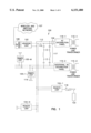
- FIG. 1 is a block diagram of an embodiment of an RF distribution system, indicated generally at 100, and constructed according to the teachings of the present invention.
- System 100 includes head end unit 102 that communicates with a number of remote units 104-1 through 104-N, and 105-1 through 105-M over power lines 106 in a closed structure, e.g., within a building, collection of buildings, or other substantially closed environment.
- Head end unit 102 is coupled to RF source 108.
- RF source 108 may comprise, for example, a conventional antenna, an RF transport unit that uses either fiber-optics or copper cable to carry signals to and from a base station, or a co-located base station unit of a wireless communication system.
- RF source 108 is coupled to wireless and switched network 107 by either a wired or wireless communication path.
- Head end unit 102 is also connected to power lines 106, including circuit ground 110 and circuit hot 112.
- head end unit 102 includes a circuit that derives DC power for head end unit 102 from the AC power on power lines 106.
- Head end unit 102 also includes an AC power line interface circuit that is coupled to one of power lines 106 to allow RF signals to be passed between one of the power lines and head end unit 102.
- the AC power line interface may be coupled to the circuit ground 110.
- Power lines 106 are coupled to AC distribution panel 116-1 which receives power from transformer 115-1 as is conventional in wiring systems for a closed structure.
- power lines 106 may comprise, for example, a dedicated or closed wiring system.
- closed wiring systems include but are not limited to emergency lighting systems, exit sign system or other circuits that are dedicated to provide power to a specified and limited number of devices. These closed wiring systems provide the advantage of not being as susceptible to RF shorts when additional devices are plugged into the wiring system.
- lighting circuits in a building provide a relatively constant transmission system for communication between head end unit 102 and remote units 104-1 through 104-N, and 105-1 through 105-M.
- system 100 may be installed in a closed structure with power lines 106 that are divided into a number of isolated AC power circuits as shown in FIG. 1.
- System 100 uses the power lines associated with ac distribution panel 116-1 and additional AC distribution panel 116-2 to distribute signals within the closed structure.
- RF "jumpers” such as AC blocking/RF coupling circuit 117 are used to carry RF signals from one power circuit to another power circuit.
- AC blocking/RF coupling circuit 117 is tuned to a second frequency to facilitate RF coupling between the isolated AC power circuits.
- Remote unit 104-1 is coupled to power lines 106. Namely, remote unit 104-1 includes a first terminal that is coupled to circuit hot line 112 and a second terminal that is coupled to circuit ground line 110. Remote unit 104-1 also is coupled to antenna 118 for distributing RF signals to and from wireless terminals 122 within the closed structure. Capacitor 120 is also coupled between remote unit 104-1 and circuit ground 110. The remaining remote units are similarly coupled to power lines 106.
- system 100 distributes RF signals to wireless terminals 122 using power lines 106 to route the signals to and from an antenna within the vicinity of wireless terminal 122.
- RF source 108 receives signals for, e.g., wireless terminal 122 at an over-the-air frequency specified from wireless and switched networks 107.
- Head end unit 102 converts the over-the-air frequency from RF source 108 to an appropriate intermediate transport frequency for transmission over power lines 106. For example, it has been determined that the frequency range from approximately 100 megahertz to 500 megahertz provides reasonable transport distances with acceptable noise levels for power lines 106.
- Remote units 104-1 through 104-N, and 105-1 through 105-M convert the frequency range of the signals from power lines 106 to the over-the-air frequency range of the signals received from RF source 108.
- antenna 118 transmits the signals within the confines of the closed structure for receipt by wireless terminal 122.
- wireless terminal 122 transmits signals to, e.g., remote unit 104-1.
- Remote unit 104-1 converts the over-the-air frequency of these signals to an intermediate transport frequency that is used on power lines 106.
- Head end unit 102 receives signals from remote units 104-1 through 104-N, and 105-1 through 105-M and converts the frequency range of the signals from power line 106 to the over-the-air frequency range.
- RF source 108 transmits these signals to wireless and switched networks 107. It is noted that AC blocking/RF coupling circuit 117 couples RF signals between the two AC power circuits to provide for communication between head end 102 and remote units 105-1 through 105-M.
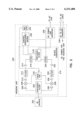
- FIG. 2 is a block diagram of an embodiment of a head end unit, indicated generally at 200, for use in an RF distribution system according to the teachings of the present invention.
- Head end unit 200 is disposed in a convenient location in a substantially closed environment that is accessible to RF signal source 204 and has access to the AC power system in the building.
- Head end unit 200 includes block converter 201 that converts RF signals between first and second frequency ranges.
- Block converter 201 includes duplexer/filter 202 that is coupled to RF source 204.
- RF source 204 may comprise, for example, a conventional antenna, an RF transport unit that uses either fiber-optics or copper from a base station, or a co-located base station unit.
- Duplexer/filter 202 is coupled to both a forward and a reverse path.
- block converter 201 includes the serial connection of amplifier 206, mixer 208, amplifier 210, band pass filter 212, amplifier 214 and attenuator 216.
- Attenuator 216 in the forward path is coupled to triplexer/filter 218.
- attenuator 220, amplifier 222, filter 224, amplifier 226, mixer 228 and amplifier 230 are coupled in series between triplexer/filter 218 and duplexer/filter 202.
- Block converter 201 includes local oscillator 232.
- Local oscillator 232 is coupled to mixers 208 and 228. Additionally, local oscillator 232 receives a reference signal from reference oscillator 234.
- Head end unit 200 also includes control processor/modem 236.
- Control processor/modem 236 receives the reference signal from reference oscillator 234.
- Control processor/modem 236 is also coupled to control attenuators 216 and 220 so as to establish an appropriate gain for the forward and reverse paths. Typically, this gain should be on the order of 20 to 40 dB.
- the amount of attenuation in attenuators 216 and 220 is established and stored in control processor/modem 236 when head end unit 200 is installed in a system.
- Control processor/modem 236 is also coupled to triplexer/filter 218 so as to provide a separate control signal to communicate with and control remote units in a system.
- the control signal is generated by head end unit 200 and exists outside any of the frequencies used for the transport of signals from RF source 204.
- This control signal contains set-up and alarm information for use by the remote units and initial and continuing calibration and event reporting that is used by the remote units.
- Control processor/modem 236 impresses the required information upon a control carrier and extracts responses from the remote units.
- the remote units e.g., of the type shown and described with respect to FIG. 3, also contain a microprocessor and modem to communicate with the head end unit via the control signal, and act upon the information and report abnormal events back to the head end unit (alarms).
- the alarm and control information is available at head end unit 200 to be relayed back to the network operation center for a wireless system via a wireless modem or a modem on a wired telephone system.
- Head end unit 200 also includes AC power line interface 238 that is coupled to an output of triplexer/filter 218.
- AC power line interface 238 provide for matching/isolating head end unit 200 to couple the RF energy into and extract RF energy from the AC power system.
- Head end unit 200 also includes AC to DC converter 238 that generates a DC power signal from the power on the AC line to provide power for head end unit 200.
- Other appropriate power sources can be used in place of the AC to DC converter.
- head end unit 200 operates to convert RF signals between an over-the-air frequency range to a frequency range appropriate for distribution over AC power lines in the power distribution system.
- RF signals enter head end unit 200 from RF source 204 at duplexer/filter 202.
- Duplexer/filter 202 filters out signals outside the desired range of RF signals to be processed by head end unit 200.
- Amplifier 206 is a low-noise amplifier that amplifies the desired signals and passes them along to mixer 208.
- the signals are heterodyned together with a signal from local oscillator 232, e.g., approximately 1500 Mhz for PCS, 1200 Mhz for cellular, or approximately 400 Mhz offset from the first frequency in the band, which is phase and frequency locked to reference oscillator 234 to provide end-to-end stability.
- the resulting signals from mixer 208 are in the intermediate frequency range from 100 to 500 megahertz.
- the signals are amplified and filtered by amplifiers 210 and filter 212, respectively.
- Amplifier 214 and attenuator 216 further adjust the amplification on the signals and provide the signals to triplexer/filter 218.
- AC power line interface 238 using, for example, a torodial inductive/capacitive network, provides proper isolation and maximum signal coupling conditions over a wide variety of loading conditions to pass the signals to the AC power system.
- Control information is sent from head end unit 200 to the remote units by control processor/modem 236. Communications from control processor/modem 236 is accomplished by low-speed, 9600, frequency shift keyed (FSK) control signal that contains information generated by control processor/modem 236.
- This control information provides frequency stability information for the local oscillators of the remote units, control information for the on-off amplitude, auto-calibration adjustments required by the remote units, and alarm information for failure reporting.
- AC power line interface 238 receives signals from the remote units over the AC power lines.
- Triplexer/filter 218 passes the signals through attenuator 220, amplifier 222, filter 224, amplifier 226 to mixer 228.
- mixer 228 a signal from local oscillator 232 returns the signals to the over-the-air frequency range.
- Amplifier 230 amplifies the signals and provides the signals to duplexer/filter 202.
- Duplexer/filter 202 provides the signals from amplifier 230 to RF source 204 for transmission to an external wireless or wireless and switched network.
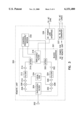
- FIG. 3 is a block diagram of an embodiment of a remote unit, indicated generally at 300, and constructed according to the teachings of the present invention.
- Remote unit 300 communicates signals to and from a wireless terminal over AC power lines to a head end unit such as head end unit 200 of FIG. 2.
- Remote unit 300 includes antenna 302 that is used to transmit and receive signals to and from the wireless terminal.
- Antenna 302 is coupled to block converter 301.
- Block converter 301 includes duplexer/filter 304.
- Duplexer/filter 304 separates out signals into reverse and forward paths for remote unit 300. In the reverse path, block converter 301 includes amplifier 306, mixer 308, amplifier 310, filter 312, amplifier 314 and attenuator 316 that are coupled in series between duplexer/filter 304 and triplexer/filter 318.
- block converter 301 includes attenuator 320, amplifier 322, filter 324, amplifier 326, mixer 328 and amplifier 330 coupled in series between triplexer/filter 318 and duplexer/filter 304.
- Remote unit 300 also includes control processor/modem 332 that is coupled to control attenuators 316 and 320 so as to adjust the gain in the forward and reverse paths when remote unit 300. Additionally, control processor/modem 332 is coupled to provide a control signal to and receive a control signal from triplexer/filter 318 of the type of signal described above with respect to head end unit 200 of FIG. 2.
- Block converter 301 also includes local oscillator 334 that is coupled to mixers 308 and 328 to provide a reference frequency for use in mixing signals in the reverse and forward paths.
- Remote unit 300 also includes AC power line interface 336 that couples signals to and from triplexer/filter 318 with the AC power system.
- Remote unit 300 also includes an AC to DC converter 337 which generates a DC power signal for remote unit 300.
- AC to DC converter 337 can be used in place of AC to DC converter 337 to provide DC power for remote unit 300.
- remote unit 300 translates signals between over-the-air frequencies and an intermediate frequency range used for transmission over the AC power lines.
- antenna 302 receives a signal from a wireless terminal in an over-the-air frequency range. This signal is passed to amplifier 306 by duplexer/filter 304.
- Mixer 308 converts, via heterodyne conversion, the frequency of the signals from amplifier 306 down to an intermediate frequency range for transmission over the AC power lines using the frequency of local oscillator 334.
- the translated signals are amplified in amplifier 310 and then filtered by band pass filter 312.
- Amplifier 314 and attenuator 316 are set so as to provide an appropriate overall gain for the reverse path.
- Triplexer/filter 318 passes the amplified and filtered signal from the reverse path to AC power line interface 336.
- AC power line interface 336 passes the signal to the AC power lines for transmission to a head end unit.
- AC power line interface 336 receives signals from the AC power lines and transmits these signals to triplexer/filter 318.
- Attenuator 320 and amplifier 322 are set so as to provide an appropriate gain, e.g. 40 dB, for the forward path.
- the output of amplifier 322 is filtered in band pass filter 324 and again amplified in amplifier 326.
- the forward signal is mixed by mixer 328 using the frequency of local oscillator 334 so as to translate the frequency of the forward signal to the range for over-the-air communication.
- the signal from mixer 328 is amplified in amplifier 330 and provided to antenna 302 by duplexer/filter 304.
- Antenna 302 may be integral with a body of remote unit 300. Antenna 302 alternatively could be a separate unit apart from remote unit 300 to facilitate placement of antenna 302. In one embodiment, antenna 302 of remote unit 300 is mounted within or on an exit sign in a building. Such exit signs are required in commercial buildings so that they are commonly visible to all the occupants of the facility and therefore provide a good antenna location.
- head end 102 of FIG. 1 does not convert the frequency of the RF signals received from antenna 108. Rather, head end 102 leaves the RF signals at the over-the-air frequencies.
- power lines 106 act as the antenna itself for broadcasting the RF signals within the building.
- This embodiment would eliminate the need for remote units 104 in certain situations, such as wood construction in private residences that use electrical wiring not installed in metallic conduits.
- This embodiment would result in a very cost-effective residential unit that could be easily deployed as an in-house booster, either as a one-way amplifier or using a bi-directional amplifier.
- a carrier sense switching circuit could be attached to the return-path amplifier to have this amplifier turn on only when subscriber units are transmitting. This would prevent the low-level noise always generated by the return-path amplifier from occupying the channel and reducing the carrier-to-noise ratio of low-level desired signals that are on the frequency.
- the system of FIG. 1 uses a dedicated feed from a base station.
- an additional set of reverse path signals are used to simulate a diversity receive path.
- the additional set of reverse-path signals are heterodyned to another frequency in order to transport a diversity receive path back to the head end and present the signal set with its phase and amplitude components to the base station as the diversity receive path.
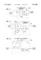
- FIGS. 4, 5 and 6 illustrate various embodiments of AC power line interface circuits that can be used in, for example, head end unit 200 of FIG. 2 or remote unit 300 of FIG. 3.
- the various AC power line interface circuits are used to match head end unit 200 or remote unit 300 with the load of the AC power system. Additionally, an AC power line interface circuit also provides the function of isolating head end unit 200 or remote unit 300 from signal spikes on the AC power line.
- AC power line interface 400 includes a one-to-one transformer 402.
- a first input of transformer 402 is coupled to the AC power line.
- a second input of transformer 402 is coupled through blocking capacitor 404 to the AC power line.
- Resistors 406 and 408 in this embodiment are provided primarily to aid in peak load protection for the head end unit 200 or remote unit 300. Additional blocking capacitors 410 and 412 are included in AC power line interface 400.
- AC power line interface 500 includes a number of variable capacitors.
- Variable capacitors 502, 504, 506 and 508 comprise, for example, discrete capacitors that are switched in and out with a rotary switch.
- AC power line interface 500 also includes a fine-tuning capacitor 510 that is continuously variable.
- AC power line interface 500 also includes shunt inductance 512 that is switched in and out of AC power line interface 500 by switch 514. Shunt inductance 512, variable capacitors 502, 504, 506 and 508 and fine-tuning capacitor 510 are used to tune AC power line interface 500 to match the RF power line.
- the variable capacitors and shunt inductance are included to allow AC power line interface 500 to be adjusted on a case-by-case basis to improve signal transfer between the power lines and the head end or remote unit.
- AC power line interface 600 includes four-to-one transformer 602 that is coupled between the AC power line and either head end unit 200 or remote unit 300.
- AC power line interface circuit 600 also includes blocking capacitor 604 and protection diodes 606 and 608.
- system 100 of FIG. 1 can be used with an AC distribution system in a closed structure with a single AC distribution panel without the need for coupling circuit 117.
- System 100 can also be used in a closed structure with more than two AC distribution panels by using additional coupling circuits 117 to couple signals from one circuit to another.
- the system with two AC distribution panels shown in FIG. 1 is shown by way of example, and not by way of limitation.
Abstract
Description
Claims (28)
Priority Applications (5)
| Application Number | Priority Date | Filing Date | Title |
|---|---|---|---|
| US08/884,533 US6151480A (en) | 1997-06-27 | 1997-06-27 | System and method for distributing RF signals over power lines within a substantially closed environment |
| EP98931602A EP0992125A2 (en) | 1997-06-27 | 1998-06-26 | System and method for distributing rf signals |
| CN98806608A CN1261480A (en) | 1997-06-27 | 1998-06-26 | System and method for distributing rf signals |
| PCT/US1998/013248 WO1999000906A2 (en) | 1997-06-27 | 1998-06-26 | System and method for distributing rf signals |
| AU81685/98A AU750814B2 (en) | 1997-06-27 | 1998-06-26 | System and method for distributing RF signals |
Applications Claiming Priority (1)
| Application Number | Priority Date | Filing Date | Title |
|---|---|---|---|
| US08/884,533 US6151480A (en) | 1997-06-27 | 1997-06-27 | System and method for distributing RF signals over power lines within a substantially closed environment |
Publications (1)
| Publication Number | Publication Date |
|---|---|
| US6151480A true US6151480A (en) | 2000-11-21 |
Family
ID=25384844
Family Applications (1)
| Application Number | Title | Priority Date | Filing Date |
|---|---|---|---|
| US08/884,533 Expired - Lifetime US6151480A (en) | 1997-06-27 | 1997-06-27 | System and method for distributing RF signals over power lines within a substantially closed environment |
Country Status (5)
| Country | Link |
|---|---|
| US (1) | US6151480A (en) |
| EP (1) | EP0992125A2 (en) |
| CN (1) | CN1261480A (en) |
| AU (1) | AU750814B2 (en) |
| WO (1) | WO1999000906A2 (en) |
Cited By (56)
| Publication number | Priority date | Publication date | Assignee | Title |
|---|---|---|---|---|
| US20010045888A1 (en) * | 2000-01-20 | 2001-11-29 | Kline Paul A. | Method of isolating data in a power line communications network |
| US20020109585A1 (en) * | 2001-02-15 | 2002-08-15 | Sanderson Lelon Wayne | Apparatus, method and system for range extension of a data communication signal on a high voltage cable |
| US20020154000A1 (en) * | 2001-02-14 | 2002-10-24 | Kline Paul A. | Data communication over a power line |
| WO2003051074A1 (en) * | 2001-12-05 | 2003-06-19 | Passover, Inc. | Multi-band cellular service over direct broadcasting service (dbs) network |
| US6653932B1 (en) * | 1999-09-29 | 2003-11-25 | Skyworks Solutions, Inc. | System and method for achieving wireless communications coverage in a local area |
| US6671501B1 (en) * | 1999-04-30 | 2003-12-30 | Polytrax Information Technology | Signal transmission circuit |
| GB2393370A (en) * | 2002-10-02 | 2004-03-24 | Artimi Ltd | Microwave frequency communication over cabling |
| WO2004032277A1 (en) * | 2002-10-02 | 2004-04-15 | Artimi Ltd | Communication methods and apparatus |
| US6737984B1 (en) * | 1997-08-15 | 2004-05-18 | General Electric Company | Automatic meter reading system using locally communicating utility meters |
| US20040130491A1 (en) * | 2001-04-26 | 2004-07-08 | David Hayes | Apparatus for providing a controllable signal delay along a transmission line |
| US6791454B2 (en) * | 2000-11-17 | 2004-09-14 | Siemens Aktiengesellschaft | Cable |
| US20050007241A1 (en) * | 2000-01-20 | 2005-01-13 | Kline Paul A. | Method of isolating data in a power line communications network |
| US20050018630A1 (en) * | 1999-04-21 | 2005-01-27 | Opencell Corp. | Architecture for signal distribution in wireless data network |
| US20050088999A1 (en) * | 2002-01-31 | 2005-04-28 | Waylett Nicholas S. | Communication system having a community wireless local area network for voice and high speed data communication |
| US20050110655A1 (en) * | 1999-02-08 | 2005-05-26 | Layton James E. | RF communication with downhole equipment |
| US20050213874A1 (en) * | 2001-02-14 | 2005-09-29 | Kline Paul A | Power line communication system and method |
| FR2871327A1 (en) * | 2004-06-08 | 2005-12-09 | Defidev | LOCAL AUDIOVISUAL DISTRIBUTION |
| US20050281326A1 (en) * | 2004-06-18 | 2005-12-22 | Hong Yu | Transceiver apparatus and method having ethernet-over-power and power-over-ethernet capability |
| US6980089B1 (en) * | 2000-08-09 | 2005-12-27 | Current Technologies, Llc | Non-intrusive coupling to shielded power cable |
| US20050285800A1 (en) * | 2004-06-29 | 2005-12-29 | Reece John K | Antennae attachable to an electronic device enclosure or other structure |
| US6997418B1 (en) * | 1997-11-05 | 2006-02-14 | Ge-Harris Raliway Electronics, L.L.C. | Methods and apparatus for testing a train control system |
| EP1667338A1 (en) * | 2004-12-02 | 2006-06-07 | Swisscom Mobile AG | Cellular mobile network and method for incorporating a base station of a cellular mobile network in a facility being fed by a power supply system |
| US7187276B2 (en) * | 2001-02-14 | 2007-03-06 | Current Technologies, Llc | Power line communication system and method of using the same |
| WO2006050331A3 (en) * | 2004-10-28 | 2007-03-22 | Corridor Systems Inc | Distributed antenna system using overhead power lines |
| US20070186256A1 (en) * | 2001-07-01 | 2007-08-09 | Phonex Broadband Corporation | Method and system for a low cost wireless telephone link for a set top box |
| US20070189182A1 (en) * | 2006-02-14 | 2007-08-16 | Berkman William H | Method for establishing power line communication link |
| US20070280246A1 (en) * | 2006-05-31 | 2007-12-06 | Berkman William H | System and Method for Communicating in a Multi-Unit Structure |
| US20070280201A1 (en) * | 2006-05-31 | 2007-12-06 | Berkman William H | System and Method for Communicating in a Multi-Unit Structure |
| US20080040295A1 (en) * | 2006-08-10 | 2008-02-14 | V2 Green, Inc. | Power Aggregation System for Distributed Electric Resources |
| US20080079631A1 (en) * | 2006-09-28 | 2008-04-03 | Sherman Chih Lo | Method and system for deriving location information from utility lines |
| US20080125187A1 (en) * | 2006-11-03 | 2008-05-29 | Yu-Chuan Chang | Wireless transmission system suitable for large space and method thereof |
| US20080130640A1 (en) * | 2005-10-03 | 2008-06-05 | Jonathan Ephraim David Hurwitz | Multi-Wideband Communications over Multiple Mediums |
| US7653015B2 (en) | 1998-07-28 | 2010-01-26 | Mosaid Technologies Incorporated | Local area network of serial intelligent cells |
| US7656904B2 (en) | 2003-03-13 | 2010-02-02 | Mosaid Technologies Incorporated | Telephone system having multiple distinct sources and accessories therefor |
| US7702095B2 (en) | 2003-01-30 | 2010-04-20 | Mosaid Technologies Incorporated | Method and system for providing DC power on local telephone lines |
| US7701325B2 (en) | 2002-12-10 | 2010-04-20 | Current Technologies, Llc | Power line communication apparatus and method of using the same |
| US7715441B2 (en) | 2000-04-19 | 2010-05-11 | Mosaid Technologies Incorporated | Network combining wired and non-wired segments |
| US7715534B2 (en) | 2000-03-20 | 2010-05-11 | Mosaid Technologies Incorporated | Telephone outlet for implementing a local area network over telephone lines and a local area network using such outlets |
| US7813451B2 (en) | 2006-01-11 | 2010-10-12 | Mobileaccess Networks Ltd. | Apparatus and method for frequency shifting of a wireless signal and systems using frequency shifting |
| US7856032B2 (en) | 2005-04-04 | 2010-12-21 | Current Technologies, Llc | Multi-function modem device |
| US20110216751A1 (en) * | 1999-04-21 | 2011-09-08 | Lgc Wireless, Inc. | Architecture for signal and power distribution in wireless data network |
| US8175649B2 (en) | 2008-06-20 | 2012-05-08 | Corning Mobileaccess Ltd | Method and system for real time control of an active antenna over a distributed antenna system |
| US8193977B1 (en) * | 2007-04-24 | 2012-06-05 | Broadcom Corporation | Power line GPS data distribution |
| US8325759B2 (en) | 2004-05-06 | 2012-12-04 | Corning Mobileaccess Ltd | System and method for carrying a wireless based signal over wiring |
| US8351582B2 (en) | 1999-07-20 | 2013-01-08 | Mosaid Technologies Incorporated | Network for telephony and data communication |
| US8582598B2 (en) | 1999-07-07 | 2013-11-12 | Mosaid Technologies Incorporated | Local area network for distributing data communication, sensing and control signals |
| US8594133B2 (en) | 2007-10-22 | 2013-11-26 | Corning Mobileaccess Ltd. | Communication system using low bandwidth wires |
| US8897215B2 (en) | 2009-02-08 | 2014-11-25 | Corning Optical Communications Wireless Ltd | Communication system using cables carrying ethernet signals |
| US9179321B2 (en) | 2012-08-09 | 2015-11-03 | Axell Wireless Ltd. | Digital capacity centric distributed antenna system |
| US9184960B1 (en) | 2014-09-25 | 2015-11-10 | Corning Optical Communications Wireless Ltd | Frequency shifting a communications signal(s) in a multi-frequency distributed antenna system (DAS) to avoid or reduce frequency interference |
| US9338823B2 (en) | 2012-03-23 | 2016-05-10 | Corning Optical Communications Wireless Ltd | Radio-frequency integrated circuit (RFIC) chip(s) for providing distributed antenna system functionalities, and related components, systems, and methods |
| US9395441B1 (en) * | 2010-04-21 | 2016-07-19 | Qualcomm Incorporated | Powerline-aided satellite-based navigation system |
| US10396917B2 (en) | 2014-09-23 | 2019-08-27 | Axell Wireless Ltd. | Automatic mapping and handling PIM and other uplink interferences in digital distributed antenna systems |
| US10986164B2 (en) | 2004-01-13 | 2021-04-20 | May Patents Ltd. | Information device |
| US11064501B2 (en) | 2014-12-23 | 2021-07-13 | Axell Wireless Ltd. | Harmonizing noise aggregation and noise management in distributed antenna system |
| US11496983B2 (en) | 2015-05-29 | 2022-11-08 | Apple Inc. | Techniques for selecting conducted RF links for mitigating multi-radio coexistence |
Families Citing this family (9)
| Publication number | Priority date | Publication date | Assignee | Title |
|---|---|---|---|---|
| US6778817B1 (en) * | 1998-12-01 | 2004-08-17 | Phonex Corporation | Method and system for combining wireless phone jack and RF wireless communications |
| WO2000038346A1 (en) * | 1998-12-22 | 2000-06-29 | Siemens Aktiengesellschaft | Method for transmitting communications information and corresponding communications unit and communications system |
| DE19920024A1 (en) * | 1999-04-27 | 2000-12-14 | Mannesmann Ag | High-frequency feed in low-voltage power lines |
| WO2002009462A1 (en) * | 2000-07-26 | 2002-01-31 | Swisscom Mobile Ag | Method for the assembly of a mobile radio network base station and connection of the base station to the network |
| CN1618191B (en) * | 2002-01-30 | 2010-04-14 | 艾利森电话股份有限公司 | Method and system for transmission of carrier sighal occupying different radio frequency band between first and second antenna networks |
| CN101145811B (en) * | 2006-09-11 | 2012-09-05 | 索尼株式会社 | Communication system, communication apparatus, and high frequency coupling equipment |
| EP2944131A1 (en) | 2013-01-08 | 2015-11-18 | Whoop Wireless LLC | A system, a device and a method for adjusting signal strength in a distributed amplifier system |
| CN106341162A (en) * | 2015-07-07 | 2017-01-18 | 华为技术有限公司 | Communication method and equipment |
| CN113784425B (en) * | 2021-09-23 | 2023-05-26 | 新华三技术有限公司 | Wireless network energy saving method and device |
Citations (38)
| Publication number | Priority date | Publication date | Assignee | Title |
|---|---|---|---|---|
| US3818481A (en) * | 1972-08-14 | 1974-06-18 | Codata Corp | Multiple address direct coupled communication and control current carrier system |
| US3876984A (en) * | 1974-04-19 | 1975-04-08 | Concord Computing Corp | Apparatus for utilizing an a.c. power line to couple a remote terminal to a central computer in a communication system |
| US3944723A (en) * | 1974-12-05 | 1976-03-16 | General Electric Company | Station for power line access data system |
| US3964048A (en) * | 1974-01-28 | 1976-06-15 | General Public Utilities Corporation | Communicating over power network within a building or other user location |
| US4520363A (en) * | 1983-03-16 | 1985-05-28 | General Instrument Corporation | Omnidirectional vertical antenna with improved high-angle coverage |
| US4538136A (en) * | 1981-03-30 | 1985-08-27 | Amtel Systems Corporation | Power line communication system utilizing a local oscillator |
| US4577333A (en) * | 1984-09-13 | 1986-03-18 | Gridcomm Inc. | Composite shift keying communication system |
| US4638496A (en) * | 1982-02-11 | 1987-01-20 | Jensen Garold K | Secure reliable transmitting and receiving system for transfer of digital data |
| US4675691A (en) * | 1985-05-23 | 1987-06-23 | Moore Richard L | Split curved plate antenna |
| US4701763A (en) * | 1984-09-17 | 1987-10-20 | Matsushita Electric Industrial Co., Ltd. | Small antenna |
| US4701764A (en) * | 1985-01-28 | 1987-10-20 | Societe de Maintenance Electronique "SOMELEC" | Miniature high-gain antenna |
| US4907006A (en) * | 1988-03-10 | 1990-03-06 | Kabushiki Kaisha Toyota Chuo Kenkyusho | Wide band antenna for mobile communications |
| US4994820A (en) * | 1988-12-16 | 1991-02-19 | Nissan Motor Co., Ltd. | Plane antenna |
| US5010349A (en) * | 1989-04-12 | 1991-04-23 | Nissan Motor Company, Ltd. | Plane patch antenna |
| US5061938A (en) * | 1987-11-13 | 1991-10-29 | Dornier System Gmbh | Microstrip antenna |
| US5151838A (en) * | 1989-09-20 | 1992-09-29 | Dockery Gregory A | Video multiplying system |
| US5270721A (en) * | 1989-05-15 | 1993-12-14 | Matsushita Electric Works, Ltd. | Planar antenna |
| US5291210A (en) * | 1988-12-27 | 1994-03-01 | Harada Kogyo Kabushiki Kaisha | Flat-plate antenna with strip line resonator having capacitance for impedance matching the feeder |
| US5300936A (en) * | 1992-09-30 | 1994-04-05 | Loral Aerospace Corp. | Multiple band antenna |
| US5319634A (en) * | 1991-10-07 | 1994-06-07 | Phoenix Corporation | Multiple access telephone extension systems and methods |
| US5327230A (en) * | 1989-09-20 | 1994-07-05 | Dockery Gregory A | Video multiplying system |
| US5351272A (en) * | 1992-05-18 | 1994-09-27 | Abraham Karoly C | Communications apparatus and method for transmitting and receiving multiple modulated signals over electrical lines |
| US5404570A (en) * | 1992-11-23 | 1995-04-04 | Telefonaktiebolaget L M Ericsson | Radio coverage in closed environments |
| US5457557A (en) * | 1994-01-21 | 1995-10-10 | Ortel Corporation | Low cost optical fiber RF signal distribution system |
| WO1995029537A1 (en) * | 1994-04-21 | 1995-11-02 | Norweb Plc | Powerline communications network employing tdma, fdma and/or cdma |
| US5475394A (en) * | 1991-01-30 | 1995-12-12 | Comsat Corporation | Waveguide transition for flat plate antenna |
| US5497142A (en) * | 1991-10-17 | 1996-03-05 | Electricite De France | Directional separator-coupler circuit for medium-frequency carrier currents on a low-voltage electrical line |
| US5499033A (en) * | 1993-07-02 | 1996-03-12 | Northern Telecom Limited | Polarization diversity antenna |
| US5510802A (en) * | 1993-04-23 | 1996-04-23 | Murata Manufacturing Co., Ltd. | Surface-mountable antenna unit |
| US5526003A (en) * | 1993-07-30 | 1996-06-11 | Matsushita Electric Industrial Co., Ltd. | Antenna for mobile communication |
| US5581229A (en) * | 1990-12-19 | 1996-12-03 | Hunt Technologies, Inc. | Communication system for a power distribution line |
| US5608391A (en) * | 1995-05-11 | 1997-03-04 | Minnesota Mining And Manufacturing Company | Electronic license plate architecture |
| US5621571A (en) * | 1994-02-14 | 1997-04-15 | Minnesota Mining And Manufacturing Company | Integrated retroreflective electronic display |
| US5630204A (en) * | 1995-05-01 | 1997-05-13 | Bell Atlantic Network Services, Inc. | Customer premise wireless distribution of broad band signals and two-way communication of control signals over power lines |
| US5668562A (en) * | 1996-04-19 | 1997-09-16 | Lgc Wireless, Inc. | Measurement-based method of optimizing the placement of antennas in a RF distribution system |
| GB2313273A (en) * | 1996-05-16 | 1997-11-19 | Northern Telecom Ltd | A telecommunications method and system and a subscriber`s interface unit of the system |
| US5765099A (en) * | 1996-04-19 | 1998-06-09 | Georges; John B. | Distribution of radio-frequency signals through low bandwidth infrastructures |
| US5774789A (en) * | 1995-12-14 | 1998-06-30 | Allen Telecom Inc. | RF communication signal distribution system and method |
-
1997
- 1997-06-27 US US08/884,533 patent/US6151480A/en not_active Expired - Lifetime
-
1998
- 1998-06-26 WO PCT/US1998/013248 patent/WO1999000906A2/en not_active Application Discontinuation
- 1998-06-26 CN CN98806608A patent/CN1261480A/en active Pending
- 1998-06-26 EP EP98931602A patent/EP0992125A2/en not_active Withdrawn
- 1998-06-26 AU AU81685/98A patent/AU750814B2/en not_active Ceased
Patent Citations (39)
| Publication number | Priority date | Publication date | Assignee | Title |
|---|---|---|---|---|
| US3818481A (en) * | 1972-08-14 | 1974-06-18 | Codata Corp | Multiple address direct coupled communication and control current carrier system |
| US3964048A (en) * | 1974-01-28 | 1976-06-15 | General Public Utilities Corporation | Communicating over power network within a building or other user location |
| US3876984A (en) * | 1974-04-19 | 1975-04-08 | Concord Computing Corp | Apparatus for utilizing an a.c. power line to couple a remote terminal to a central computer in a communication system |
| US3944723A (en) * | 1974-12-05 | 1976-03-16 | General Electric Company | Station for power line access data system |
| US4538136A (en) * | 1981-03-30 | 1985-08-27 | Amtel Systems Corporation | Power line communication system utilizing a local oscillator |
| US4638496A (en) * | 1982-02-11 | 1987-01-20 | Jensen Garold K | Secure reliable transmitting and receiving system for transfer of digital data |
| US4520363A (en) * | 1983-03-16 | 1985-05-28 | General Instrument Corporation | Omnidirectional vertical antenna with improved high-angle coverage |
| US4577333A (en) * | 1984-09-13 | 1986-03-18 | Gridcomm Inc. | Composite shift keying communication system |
| US4701763A (en) * | 1984-09-17 | 1987-10-20 | Matsushita Electric Industrial Co., Ltd. | Small antenna |
| US4701764A (en) * | 1985-01-28 | 1987-10-20 | Societe de Maintenance Electronique "SOMELEC" | Miniature high-gain antenna |
| US4675691A (en) * | 1985-05-23 | 1987-06-23 | Moore Richard L | Split curved plate antenna |
| US5061938A (en) * | 1987-11-13 | 1991-10-29 | Dornier System Gmbh | Microstrip antenna |
| US4907006A (en) * | 1988-03-10 | 1990-03-06 | Kabushiki Kaisha Toyota Chuo Kenkyusho | Wide band antenna for mobile communications |
| US4994820A (en) * | 1988-12-16 | 1991-02-19 | Nissan Motor Co., Ltd. | Plane antenna |
| US5291210A (en) * | 1988-12-27 | 1994-03-01 | Harada Kogyo Kabushiki Kaisha | Flat-plate antenna with strip line resonator having capacitance for impedance matching the feeder |
| US5010349A (en) * | 1989-04-12 | 1991-04-23 | Nissan Motor Company, Ltd. | Plane patch antenna |
| US5270721A (en) * | 1989-05-15 | 1993-12-14 | Matsushita Electric Works, Ltd. | Planar antenna |
| US5151838A (en) * | 1989-09-20 | 1992-09-29 | Dockery Gregory A | Video multiplying system |
| US5327230A (en) * | 1989-09-20 | 1994-07-05 | Dockery Gregory A | Video multiplying system |
| US5581229A (en) * | 1990-12-19 | 1996-12-03 | Hunt Technologies, Inc. | Communication system for a power distribution line |
| US5475394A (en) * | 1991-01-30 | 1995-12-12 | Comsat Corporation | Waveguide transition for flat plate antenna |
| US5319634A (en) * | 1991-10-07 | 1994-06-07 | Phoenix Corporation | Multiple access telephone extension systems and methods |
| US5497142A (en) * | 1991-10-17 | 1996-03-05 | Electricite De France | Directional separator-coupler circuit for medium-frequency carrier currents on a low-voltage electrical line |
| US5351272A (en) * | 1992-05-18 | 1994-09-27 | Abraham Karoly C | Communications apparatus and method for transmitting and receiving multiple modulated signals over electrical lines |
| US5300936A (en) * | 1992-09-30 | 1994-04-05 | Loral Aerospace Corp. | Multiple band antenna |
| US5404570A (en) * | 1992-11-23 | 1995-04-04 | Telefonaktiebolaget L M Ericsson | Radio coverage in closed environments |
| US5603080A (en) * | 1992-11-23 | 1997-02-11 | Telefonaktiebolaget Lm Ericsson | Radio coverage in closed environments |
| US5510802A (en) * | 1993-04-23 | 1996-04-23 | Murata Manufacturing Co., Ltd. | Surface-mountable antenna unit |
| US5499033A (en) * | 1993-07-02 | 1996-03-12 | Northern Telecom Limited | Polarization diversity antenna |
| US5526003A (en) * | 1993-07-30 | 1996-06-11 | Matsushita Electric Industrial Co., Ltd. | Antenna for mobile communication |
| US5457557A (en) * | 1994-01-21 | 1995-10-10 | Ortel Corporation | Low cost optical fiber RF signal distribution system |
| US5621571A (en) * | 1994-02-14 | 1997-04-15 | Minnesota Mining And Manufacturing Company | Integrated retroreflective electronic display |
| WO1995029537A1 (en) * | 1994-04-21 | 1995-11-02 | Norweb Plc | Powerline communications network employing tdma, fdma and/or cdma |
| US5630204A (en) * | 1995-05-01 | 1997-05-13 | Bell Atlantic Network Services, Inc. | Customer premise wireless distribution of broad band signals and two-way communication of control signals over power lines |
| US5608391A (en) * | 1995-05-11 | 1997-03-04 | Minnesota Mining And Manufacturing Company | Electronic license plate architecture |
| US5774789A (en) * | 1995-12-14 | 1998-06-30 | Allen Telecom Inc. | RF communication signal distribution system and method |
| US5668562A (en) * | 1996-04-19 | 1997-09-16 | Lgc Wireless, Inc. | Measurement-based method of optimizing the placement of antennas in a RF distribution system |
| US5765099A (en) * | 1996-04-19 | 1998-06-09 | Georges; John B. | Distribution of radio-frequency signals through low bandwidth infrastructures |
| GB2313273A (en) * | 1996-05-16 | 1997-11-19 | Northern Telecom Ltd | A telecommunications method and system and a subscriber`s interface unit of the system |
Non-Patent Citations (2)
| Title |
|---|
| "CityRFx Solutions", ADC Wireless Systems, Distributed Antenna System, 4, (1996). |
| CityRFx Solutions , ADC Wireless Systems, Distributed Antenna System , 4, (1996). * |
Cited By (126)
| Publication number | Priority date | Publication date | Assignee | Title |
|---|---|---|---|---|
| US6737984B1 (en) * | 1997-08-15 | 2004-05-18 | General Electric Company | Automatic meter reading system using locally communicating utility meters |
| US20070035414A1 (en) * | 1997-08-15 | 2007-02-15 | Welles Kenneth B Ii | Automatic meter reading system using locally communicating utility meters |
| US7652526B2 (en) | 1997-08-15 | 2010-01-26 | General Electric Company | Narrow band pass filter |
| US20040174271A1 (en) * | 1997-08-15 | 2004-09-09 | Welles Kenneth Brakeley | Automatic meter reading system using locally communicating utility meters |
| US6997418B1 (en) * | 1997-11-05 | 2006-02-14 | Ge-Harris Raliway Electronics, L.L.C. | Methods and apparatus for testing a train control system |
| US7978726B2 (en) | 1998-07-28 | 2011-07-12 | Mosaid Technologies Incorporated | Local area network of serial intelligent cells |
| US7965735B2 (en) | 1998-07-28 | 2011-06-21 | Mosaid Technologies Incorporated | Local area network of serial intelligent cells |
| US8885660B2 (en) | 1998-07-28 | 2014-11-11 | Conversant Intellectual Property Management Incorporated | Local area network of serial intelligent cells |
| US8885659B2 (en) | 1998-07-28 | 2014-11-11 | Conversant Intellectual Property Management Incorporated | Local area network of serial intelligent cells |
| US7653015B2 (en) | 1998-07-28 | 2010-01-26 | Mosaid Technologies Incorporated | Local area network of serial intelligent cells |
| US8867523B2 (en) | 1998-07-28 | 2014-10-21 | Conversant Intellectual Property Management Incorporated | Local area network of serial intelligent cells |
| US7830858B2 (en) | 1998-07-28 | 2010-11-09 | Mosaid Technologies Incorporated | Local area network of serial intelligent cells |
| US7852874B2 (en) | 1998-07-28 | 2010-12-14 | Mosaid Technologies Incorporated | Local area network of serial intelligent cells |
| US8908673B2 (en) | 1998-07-28 | 2014-12-09 | Conversant Intellectual Property Management Incorporated | Local area network of serial intelligent cells |
| US7969917B2 (en) | 1998-07-28 | 2011-06-28 | Mosaid Technologies Incorporated | Local area network of serial intelligent cells |
| US7986708B2 (en) | 1998-07-28 | 2011-07-26 | Mosaid Technologies Incorporated | Local area network of serial intelligent cells |
| US8270430B2 (en) | 1998-07-28 | 2012-09-18 | Mosaid Technologies Incorporated | Local area network of serial intelligent cells |
| US8325636B2 (en) | 1998-07-28 | 2012-12-04 | Mosaid Technologies Incorporated | Local area network of serial intelligent cells |
| US20050110655A1 (en) * | 1999-02-08 | 2005-05-26 | Layton James E. | RF communication with downhole equipment |
| US7248178B2 (en) * | 1999-02-08 | 2007-07-24 | Baker Hughes Incorporated | RF communication with downhole equipment |
| US9674678B2 (en) | 1999-04-21 | 2017-06-06 | Commscope Technologies Llc | Architecture for signal and power distribution in wireless data network |
| US8379569B2 (en) | 1999-04-21 | 2013-02-19 | Adc Telecommunications, Inc. | Architecture for signal distribution in wireless data network |
| US20110216751A1 (en) * | 1999-04-21 | 2011-09-08 | Lgc Wireless, Inc. | Architecture for signal and power distribution in wireless data network |
| US20050018630A1 (en) * | 1999-04-21 | 2005-01-27 | Opencell Corp. | Architecture for signal distribution in wireless data network |
| US10142813B2 (en) | 1999-04-21 | 2018-11-27 | Commscope Technologies Llc | Architecture for signal and power distribution in wireless data network |
| US8824457B2 (en) | 1999-04-21 | 2014-09-02 | Adc Telecommunications, Inc. | Architecture for signal and power distribution in wireless data network |
| US6671501B1 (en) * | 1999-04-30 | 2003-12-30 | Polytrax Information Technology | Signal transmission circuit |
| US8582598B2 (en) | 1999-07-07 | 2013-11-12 | Mosaid Technologies Incorporated | Local area network for distributing data communication, sensing and control signals |
| US8929523B2 (en) | 1999-07-20 | 2015-01-06 | Conversant Intellectual Property Management Inc. | Network for telephony and data communication |
| US8351582B2 (en) | 1999-07-20 | 2013-01-08 | Mosaid Technologies Incorporated | Network for telephony and data communication |
| US6653932B1 (en) * | 1999-09-29 | 2003-11-25 | Skyworks Solutions, Inc. | System and method for achieving wireless communications coverage in a local area |
| US20050007241A1 (en) * | 2000-01-20 | 2005-01-13 | Kline Paul A. | Method of isolating data in a power line communications network |
| US20010045888A1 (en) * | 2000-01-20 | 2001-11-29 | Kline Paul A. | Method of isolating data in a power line communications network |
| US7176786B2 (en) | 2000-01-20 | 2007-02-13 | Current Technologies, Llc | Method of isolating data in a power line communications network |
| US8855277B2 (en) | 2000-03-20 | 2014-10-07 | Conversant Intellectual Property Managment Incorporated | Telephone outlet for implementing a local area network over telephone lines and a local area network using such outlets |
| US7715534B2 (en) | 2000-03-20 | 2010-05-11 | Mosaid Technologies Incorporated | Telephone outlet for implementing a local area network over telephone lines and a local area network using such outlets |
| US8363797B2 (en) | 2000-03-20 | 2013-01-29 | Mosaid Technologies Incorporated | Telephone outlet for implementing a local area network over telephone lines and a local area network using such outlets |
| US7933297B2 (en) | 2000-04-19 | 2011-04-26 | Mosaid Technologies Incorporated | Network combining wired and non-wired segments |
| US8873586B2 (en) | 2000-04-19 | 2014-10-28 | Conversant Intellectual Property Management Incorporated | Network combining wired and non-wired segments |
| US8873575B2 (en) | 2000-04-19 | 2014-10-28 | Conversant Intellectual Property Management Incorporated | Network combining wired and non-wired segments |
| US8289991B2 (en) | 2000-04-19 | 2012-10-16 | Mosaid Technologies Incorporated | Network combining wired and non-wired segments |
| US7876767B2 (en) | 2000-04-19 | 2011-01-25 | Mosaid Technologies Incorporated | Network combining wired and non-wired segments |
| US8982904B2 (en) | 2000-04-19 | 2015-03-17 | Conversant Intellectual Property Management Inc. | Network combining wired and non-wired segments |
| US8982903B2 (en) | 2000-04-19 | 2015-03-17 | Conversant Intellectual Property Management Inc. | Network combining wired and non-wired segments |
| US8848725B2 (en) | 2000-04-19 | 2014-09-30 | Conversant Intellectual Property Management Incorporated | Network combining wired and non-wired segments |
| US8867506B2 (en) | 2000-04-19 | 2014-10-21 | Conversant Intellectual Property Management Incorporated | Network combining wired and non-wired segments |
| US7715441B2 (en) | 2000-04-19 | 2010-05-11 | Mosaid Technologies Incorporated | Network combining wired and non-wired segments |
| US6980089B1 (en) * | 2000-08-09 | 2005-12-27 | Current Technologies, Llc | Non-intrusive coupling to shielded power cable |
| US6791454B2 (en) * | 2000-11-17 | 2004-09-14 | Siemens Aktiengesellschaft | Cable |
| US7187276B2 (en) * | 2001-02-14 | 2007-03-06 | Current Technologies, Llc | Power line communication system and method of using the same |
| US7046882B2 (en) | 2001-02-14 | 2006-05-16 | Current Technologies, Llc | Power line communication system and method |
| US7042351B2 (en) * | 2001-02-14 | 2006-05-09 | Current Technologies, Llc | Data communication over a power line |
| US20050213874A1 (en) * | 2001-02-14 | 2005-09-29 | Kline Paul A | Power line communication system and method |
| US20020154000A1 (en) * | 2001-02-14 | 2002-10-24 | Kline Paul A. | Data communication over a power line |
| US20060079198A1 (en) * | 2001-02-15 | 2006-04-13 | Sanderson Lelon W | Apparatus, method and system for range extension of a data communication signal on a high voltage cable |
| US20020109585A1 (en) * | 2001-02-15 | 2002-08-15 | Sanderson Lelon Wayne | Apparatus, method and system for range extension of a data communication signal on a high voltage cable |
| US20040130491A1 (en) * | 2001-04-26 | 2004-07-08 | David Hayes | Apparatus for providing a controllable signal delay along a transmission line |
| US20070186256A1 (en) * | 2001-07-01 | 2007-08-09 | Phonex Broadband Corporation | Method and system for a low cost wireless telephone link for a set top box |
| US7810125B2 (en) * | 2001-07-01 | 2010-10-05 | Phonex Broadband Corporation | Method and system for a low cost wireless telephone link for a set top box |
| WO2003051074A1 (en) * | 2001-12-05 | 2003-06-19 | Passover, Inc. | Multi-band cellular service over direct broadcasting service (dbs) network |
| US20050088999A1 (en) * | 2002-01-31 | 2005-04-28 | Waylett Nicholas S. | Communication system having a community wireless local area network for voice and high speed data communication |
| US10659970B2 (en) | 2002-01-31 | 2020-05-19 | Commscope Technologies Llc | Communication system having a community wireless local area network for voice and high speed data communication |
| US8184603B2 (en) | 2002-01-31 | 2012-05-22 | Lgc Wireless, Llc | Communication system having a community wireless local area network for voice and high speed data communication |
| GB2393370B (en) * | 2002-10-02 | 2004-10-20 | Artimi Ltd | Communication methods & apparatus |
| WO2004032277A1 (en) * | 2002-10-02 | 2004-04-15 | Artimi Ltd | Communication methods and apparatus |
| WO2004032363A1 (en) * | 2002-10-02 | 2004-04-15 | Artimi Ltd | Communication methods and apparatus |
| GB2393370A (en) * | 2002-10-02 | 2004-03-24 | Artimi Ltd | Microwave frequency communication over cabling |
| US20050164666A1 (en) * | 2002-10-02 | 2005-07-28 | Lang Jack A. | Communication methods and apparatus |
| US7701325B2 (en) | 2002-12-10 | 2010-04-20 | Current Technologies, Llc | Power line communication apparatus and method of using the same |
| US7702095B2 (en) | 2003-01-30 | 2010-04-20 | Mosaid Technologies Incorporated | Method and system for providing DC power on local telephone lines |
| US8787562B2 (en) | 2003-01-30 | 2014-07-22 | Conversant Intellectual Property Management Inc. | Method and system for providing DC power on local telephone lines |
| US8107618B2 (en) | 2003-01-30 | 2012-01-31 | Mosaid Technologies Incorporated | Method and system for providing DC power on local telephone lines |
| US7656904B2 (en) | 2003-03-13 | 2010-02-02 | Mosaid Technologies Incorporated | Telephone system having multiple distinct sources and accessories therefor |
| US10986164B2 (en) | 2004-01-13 | 2021-04-20 | May Patents Ltd. | Information device |
| US11095708B2 (en) | 2004-01-13 | 2021-08-17 | May Patents Ltd. | Information device |
| US11032353B2 (en) | 2004-01-13 | 2021-06-08 | May Patents Ltd. | Information device |
| US8325759B2 (en) | 2004-05-06 | 2012-12-04 | Corning Mobileaccess Ltd | System and method for carrying a wireless based signal over wiring |
| US8325693B2 (en) | 2004-05-06 | 2012-12-04 | Corning Mobileaccess Ltd | System and method for carrying a wireless based signal over wiring |
| EP1605603A1 (en) * | 2004-06-08 | 2005-12-14 | Defidev | Local audiovisual distribution with PLC |
| FR2871327A1 (en) * | 2004-06-08 | 2005-12-09 | Defidev | LOCAL AUDIOVISUAL DISTRIBUTION |
| US20050281326A1 (en) * | 2004-06-18 | 2005-12-22 | Hong Yu | Transceiver apparatus and method having ethernet-over-power and power-over-ethernet capability |
| US7660345B2 (en) * | 2004-06-18 | 2010-02-09 | Aboundi, Inc. | Transceiver apparatus and method having ethernet-over-power and power-over-ethernet capability |
| US8045602B2 (en) * | 2004-06-18 | 2011-10-25 | Aboundi, Inc. | Transceiver apparatus and method having ethernet-over-power and power-over-ethernet capability |
| US20100118928A1 (en) * | 2004-06-18 | 2010-05-13 | Hong Yu | Transceiver Apparatus and Method Having Ethernet-Over-Power and Power-Over-Ethernet Capability |
| US7834810B2 (en) * | 2004-06-29 | 2010-11-16 | Intel Corporation | Antennae attachable to an electronic device enclosure or other structure |
| US20050285800A1 (en) * | 2004-06-29 | 2005-12-29 | Reece John K | Antennae attachable to an electronic device enclosure or other structure |
| US20090079660A1 (en) * | 2004-10-28 | 2009-03-26 | Corridor Systems, Inc. | Distributed antenna system using overhead power lines |
| WO2006050331A3 (en) * | 2004-10-28 | 2007-03-22 | Corridor Systems Inc | Distributed antenna system using overhead power lines |
| US20060142066A1 (en) * | 2004-12-02 | 2006-06-29 | Swisscom Mobile Ag | Cellular mobile radio network and method for setting up a base station of a cellular mobile radio network |
| EP1667338A1 (en) * | 2004-12-02 | 2006-06-07 | Swisscom Mobile AG | Cellular mobile network and method for incorporating a base station of a cellular mobile network in a facility being fed by a power supply system |
| US7684823B2 (en) * | 2004-12-02 | 2010-03-23 | Swisscom Mobile Ag | Cellular mobile radio network and method for setting up a base station of a cellular mobile radio network |
| US7856032B2 (en) | 2005-04-04 | 2010-12-21 | Current Technologies, Llc | Multi-function modem device |
| US9036649B2 (en) * | 2005-10-03 | 2015-05-19 | Broadcom Corporation | Multi-wideband communications over multiple mediums |
| US20080130640A1 (en) * | 2005-10-03 | 2008-06-05 | Jonathan Ephraim David Hurwitz | Multi-Wideband Communications over Multiple Mediums |
| US20130177025A1 (en) * | 2005-10-03 | 2013-07-11 | Broadcom Corporation | Multi-wideband communications over multiple mediums |
| US8406239B2 (en) * | 2005-10-03 | 2013-03-26 | Broadcom Corporation | Multi-wideband communications over multiple mediums |
| US7813451B2 (en) | 2006-01-11 | 2010-10-12 | Mobileaccess Networks Ltd. | Apparatus and method for frequency shifting of a wireless signal and systems using frequency shifting |
| US8184681B2 (en) | 2006-01-11 | 2012-05-22 | Corning Mobileaccess Ltd | Apparatus and method for frequency shifting of a wireless signal and systems using frequency shifting |
| US7852207B2 (en) | 2006-02-14 | 2010-12-14 | Current Technologies, Llc | Method for establishing power line communication link |
| US20070189182A1 (en) * | 2006-02-14 | 2007-08-16 | Berkman William H | Method for establishing power line communication link |
| US7602695B2 (en) | 2006-05-31 | 2009-10-13 | Current Technologies, Llc | System and method for communicating in a multi-unit structure |
| US20070280201A1 (en) * | 2006-05-31 | 2007-12-06 | Berkman William H | System and Method for Communicating in a Multi-Unit Structure |
| US7596079B2 (en) | 2006-05-31 | 2009-09-29 | Current Technologies, Llc | System and method for communicating in a multi-unit structure |
| US20070280246A1 (en) * | 2006-05-31 | 2007-12-06 | Berkman William H | System and Method for Communicating in a Multi-Unit Structure |
| US20080040295A1 (en) * | 2006-08-10 | 2008-02-14 | V2 Green, Inc. | Power Aggregation System for Distributed Electric Resources |
| US8120533B2 (en) * | 2006-09-28 | 2012-02-21 | The Board Of Trustees Of The Leland Stanford Junior University | Method and system for deriving location information from utility lines |
| US20080079631A1 (en) * | 2006-09-28 | 2008-04-03 | Sherman Chih Lo | Method and system for deriving location information from utility lines |
| US20080125187A1 (en) * | 2006-11-03 | 2008-05-29 | Yu-Chuan Chang | Wireless transmission system suitable for large space and method thereof |
| US8193977B1 (en) * | 2007-04-24 | 2012-06-05 | Broadcom Corporation | Power line GPS data distribution |
| US9813229B2 (en) | 2007-10-22 | 2017-11-07 | Corning Optical Communications Wireless Ltd | Communication system using low bandwidth wires |
| US8594133B2 (en) | 2007-10-22 | 2013-11-26 | Corning Mobileaccess Ltd. | Communication system using low bandwidth wires |
| US9549301B2 (en) | 2007-12-17 | 2017-01-17 | Corning Optical Communications Wireless Ltd | Method and system for real time control of an active antenna over a distributed antenna system |
| US8175649B2 (en) | 2008-06-20 | 2012-05-08 | Corning Mobileaccess Ltd | Method and system for real time control of an active antenna over a distributed antenna system |
| US8897215B2 (en) | 2009-02-08 | 2014-11-25 | Corning Optical Communications Wireless Ltd | Communication system using cables carrying ethernet signals |
| US9395441B1 (en) * | 2010-04-21 | 2016-07-19 | Qualcomm Incorporated | Powerline-aided satellite-based navigation system |
| US9948329B2 (en) | 2012-03-23 | 2018-04-17 | Corning Optical Communications Wireless, LTD | Radio-frequency integrated circuit (RFIC) chip(s) for providing distributed antenna system functionalities, and related components, systems, and methods |
| US10141959B2 (en) | 2012-03-23 | 2018-11-27 | Corning Optical Communications Wireless Ltd | Radio-frequency integrated circuit (RFIC) chip(s) for providing distributed antenna system functionalities, and related components, systems, and methods |
| US9338823B2 (en) | 2012-03-23 | 2016-05-10 | Corning Optical Communications Wireless Ltd | Radio-frequency integrated circuit (RFIC) chip(s) for providing distributed antenna system functionalities, and related components, systems, and methods |
| US9179321B2 (en) | 2012-08-09 | 2015-11-03 | Axell Wireless Ltd. | Digital capacity centric distributed antenna system |
| US9794791B2 (en) | 2012-08-09 | 2017-10-17 | Axell Wireless Ltd. | Digital capacity centric distributed antenna system |
| US10396917B2 (en) | 2014-09-23 | 2019-08-27 | Axell Wireless Ltd. | Automatic mapping and handling PIM and other uplink interferences in digital distributed antenna systems |
| US9253003B1 (en) | 2014-09-25 | 2016-02-02 | Corning Optical Communications Wireless Ltd | Frequency shifting a communications signal(S) in a multi-frequency distributed antenna system (DAS) to avoid or reduce frequency interference |
| US9184960B1 (en) | 2014-09-25 | 2015-11-10 | Corning Optical Communications Wireless Ltd | Frequency shifting a communications signal(s) in a multi-frequency distributed antenna system (DAS) to avoid or reduce frequency interference |
| US9515855B2 (en) | 2014-09-25 | 2016-12-06 | Corning Optical Communications Wireless Ltd | Frequency shifting a communications signal(s) in a multi-frequency distributed antenna system (DAS) to avoid or reduce frequency interference |
| US11064501B2 (en) | 2014-12-23 | 2021-07-13 | Axell Wireless Ltd. | Harmonizing noise aggregation and noise management in distributed antenna system |
| US11496983B2 (en) | 2015-05-29 | 2022-11-08 | Apple Inc. | Techniques for selecting conducted RF links for mitigating multi-radio coexistence |
Also Published As
| Publication number | Publication date |
|---|---|
| WO1999000906A3 (en) | 1999-04-15 |
| AU750814B2 (en) | 2002-07-25 |
| CN1261480A (en) | 2000-07-26 |
| WO1999000906A2 (en) | 1999-01-07 |
| AU8168598A (en) | 1999-01-19 |
| EP0992125A2 (en) | 2000-04-12 |
Similar Documents
| Publication | Publication Date | Title |
|---|---|---|
| US6151480A (en) | System and method for distributing RF signals over power lines within a substantially closed environment | |
| US5812933A (en) | Duplex RF repeater for personal communications system | |
| US7706744B2 (en) | Wireless repeater implementing low-level oscillation detection and protection for a duplex communication system | |
| US6029048A (en) | Repeater system having reduced power loss | |
| CA2049615A1 (en) | Radio relay system, cordless telephone system, base station device, and radio system | |
| CN1145706A (en) | Cellular radio system, repeater and base station | |
| EP0468688B1 (en) | Method and apparatus for providing wireless communications between remote locations | |
| US20010038670A1 (en) | Multibit spread spectrum signalling | |
| US20070010198A1 (en) | Method and apparatus for utilizing selective signal polarization and interference cancellation for wireless communication | |
| US8346163B2 (en) | Radio frequency signal distribution using data cable system | |
| KR100627189B1 (en) | Relay System Using Common Power in Wireless Communication Network | |
| RU2201023C2 (en) | Method and device for integrating plurality of antennas into distributed-antenna communication system | |
| US10454662B2 (en) | Duplexer with signal cancellation | |
| EP0873014A1 (en) | Process and system for distributing television signals | |
| KR100285086B1 (en) | Underground Wireless Network Relay System | |
| US8289888B2 (en) | System for cellular communications and its units | |
| US8462830B2 (en) | Radio frequency distribution with spreading | |
| EP1414241B1 (en) | System for the transparent transfer of radio frequency signals onto a cabled network | |
| KR101052175B1 (en) | Apparatus and method for mobile communication signal relay using CYPEN reserve circuit | |
| KR200251636Y1 (en) | Unified repeating system for mobile communication service | |
| AU2003270994A1 (en) | System for the transparent translation of high frequency radio signals on a cabled network |
Legal Events
| Date | Code | Title | Description |
|---|---|---|---|
| AS | Assignment |
Owner name: ADC TELECOMMUNICATIONS, INC., MINNESOTA Free format text: ASSIGNMENT OF ASSIGNORS INTEREST;ASSIGNORS:FISCHER, LARRY G.;RUSSELL, DAVID S.;REEL/FRAME:008937/0461;SIGNING DATES FROM 19971014 TO 19971104 |
|
| STCF | Information on status: patent grant |
Free format text: PATENTED CASE |
|
| FPAY | Fee payment |
Year of fee payment: 4 |
|
| FPAY | Fee payment |
Year of fee payment: 8 |
|
| FPAY | Fee payment |
Year of fee payment: 12 |
|
| AS | Assignment |
Owner name: TYCO ELECTRONICS SERVICES GMBH, SWITZERLAND Free format text: ASSIGNMENT OF ASSIGNORS INTEREST;ASSIGNOR:ADC TELECOMMUNICATIONS, INC.;REEL/FRAME:036060/0174 Effective date: 20110930 |
|
| AS | Assignment |
Owner name: COMMSCOPE EMEA LIMITED, IRELAND Free format text: ASSIGNMENT OF ASSIGNORS INTEREST;ASSIGNOR:TYCO ELECTRONICS SERVICES GMBH;REEL/FRAME:036956/0001 Effective date: 20150828 |
|
| AS | Assignment |
Owner name: COMMSCOPE TECHNOLOGIES LLC, NORTH CAROLINA Free format text: ASSIGNMENT OF ASSIGNORS INTEREST;ASSIGNOR:COMMSCOPE EMEA LIMITED;REEL/FRAME:037012/0001 Effective date: 20150828 |
|
| AS | Assignment |
Owner name: JPMORGAN CHASE BANK, N.A., AS COLLATERAL AGENT, ILLINOIS Free format text: PATENT SECURITY AGREEMENT (TERM);ASSIGNOR:COMMSCOPE TECHNOLOGIES LLC;REEL/FRAME:037513/0709 Effective date: 20151220 Owner name: JPMORGAN CHASE BANK, N.A., AS COLLATERAL AGENT, ILLINOIS Free format text: PATENT SECURITY AGREEMENT (ABL);ASSIGNOR:COMMSCOPE TECHNOLOGIES LLC;REEL/FRAME:037514/0196 Effective date: 20151220 Owner name: JPMORGAN CHASE BANK, N.A., AS COLLATERAL AGENT, IL Free format text: PATENT SECURITY AGREEMENT (TERM);ASSIGNOR:COMMSCOPE TECHNOLOGIES LLC;REEL/FRAME:037513/0709 Effective date: 20151220 Owner name: JPMORGAN CHASE BANK, N.A., AS COLLATERAL AGENT, IL Free format text: PATENT SECURITY AGREEMENT (ABL);ASSIGNOR:COMMSCOPE TECHNOLOGIES LLC;REEL/FRAME:037514/0196 Effective date: 20151220 |
|
| AS | Assignment |
Owner name: COMMSCOPE TECHNOLOGIES LLC, NORTH CAROLINA Free format text: RELEASE BY SECURED PARTY;ASSIGNOR:JPMORGAN CHASE BANK, N.A.;REEL/FRAME:048840/0001 Effective date: 20190404 Owner name: ALLEN TELECOM LLC, ILLINOIS Free format text: RELEASE BY SECURED PARTY;ASSIGNOR:JPMORGAN CHASE BANK, N.A.;REEL/FRAME:048840/0001 Effective date: 20190404 Owner name: COMMSCOPE, INC. OF NORTH CAROLINA, NORTH CAROLINA Free format text: RELEASE BY SECURED PARTY;ASSIGNOR:JPMORGAN CHASE BANK, N.A.;REEL/FRAME:048840/0001 Effective date: 20190404 Owner name: REDWOOD SYSTEMS, INC., NORTH CAROLINA Free format text: RELEASE BY SECURED PARTY;ASSIGNOR:JPMORGAN CHASE BANK, N.A.;REEL/FRAME:048840/0001 Effective date: 20190404 Owner name: ANDREW LLC, NORTH CAROLINA Free format text: RELEASE BY SECURED PARTY;ASSIGNOR:JPMORGAN CHASE BANK, N.A.;REEL/FRAME:048840/0001 Effective date: 20190404 Owner name: COMMSCOPE TECHNOLOGIES LLC, NORTH CAROLINA Free format text: RELEASE BY SECURED PARTY;ASSIGNOR:JPMORGAN CHASE BANK, N.A.;REEL/FRAME:049260/0001 Effective date: 20190404 Owner name: COMMSCOPE, INC. OF NORTH CAROLINA, NORTH CAROLINA Free format text: RELEASE BY SECURED PARTY;ASSIGNOR:JPMORGAN CHASE BANK, N.A.;REEL/FRAME:049260/0001 Effective date: 20190404 Owner name: REDWOOD SYSTEMS, INC., NORTH CAROLINA Free format text: RELEASE BY SECURED PARTY;ASSIGNOR:JPMORGAN CHASE BANK, N.A.;REEL/FRAME:049260/0001 Effective date: 20190404 Owner name: ANDREW LLC, NORTH CAROLINA Free format text: RELEASE BY SECURED PARTY;ASSIGNOR:JPMORGAN CHASE BANK, N.A.;REEL/FRAME:049260/0001 Effective date: 20190404 Owner name: ALLEN TELECOM LLC, ILLINOIS Free format text: RELEASE BY SECURED PARTY;ASSIGNOR:JPMORGAN CHASE BANK, N.A.;REEL/FRAME:049260/0001 Effective date: 20190404 |