US6324030B1 - Digital pes demodulation for a disk drive servo control system using synchronous digital sampling - Google Patents
Digital pes demodulation for a disk drive servo control system using synchronous digital sampling Download PDFInfo
- Publication number
- US6324030B1 US6324030B1 US08/938,267 US93826797A US6324030B1 US 6324030 B1 US6324030 B1 US 6324030B1 US 93826797 A US93826797 A US 93826797A US 6324030 B1 US6324030 B1 US 6324030B1
- Authority
- US
- United States
- Prior art keywords
- servo
- burst
- signal
- data
- quadrature
- Prior art date
- Legal status (The legal status is an assumption and is not a legal conclusion. Google has not performed a legal analysis and makes no representation as to the accuracy of the status listed.)
- Expired - Lifetime
Links
Images


Classifications
-
- G—PHYSICS
- G11—INFORMATION STORAGE
- G11B—INFORMATION STORAGE BASED ON RELATIVE MOVEMENT BETWEEN RECORD CARRIER AND TRANSDUCER
- G11B5/00—Recording by magnetisation or demagnetisation of a record carrier; Reproducing by magnetic means; Record carriers therefor
- G11B5/48—Disposition or mounting of heads or head supports relative to record carriers ; arrangements of heads, e.g. for scanning the record carrier to increase the relative speed
- G11B5/58—Disposition or mounting of heads or head supports relative to record carriers ; arrangements of heads, e.g. for scanning the record carrier to increase the relative speed with provision for moving the head for the purpose of maintaining alignment of the head relative to the record carrier during transducing operation, e.g. to compensate for surface irregularities of the latter or for track following
- G11B5/596—Disposition or mounting of heads or head supports relative to record carriers ; arrangements of heads, e.g. for scanning the record carrier to increase the relative speed with provision for moving the head for the purpose of maintaining alignment of the head relative to the record carrier during transducing operation, e.g. to compensate for surface irregularities of the latter or for track following for track following on disks
- G11B5/59688—Servo signal format patterns or signal processing thereof, e.g. dual, tri, quad, burst signal patterns
-
- G—PHYSICS
- G11—INFORMATION STORAGE
- G11B—INFORMATION STORAGE BASED ON RELATIVE MOVEMENT BETWEEN RECORD CARRIER AND TRANSDUCER
- G11B5/00—Recording by magnetisation or demagnetisation of a record carrier; Reproducing by magnetic means; Record carriers therefor
- G11B5/48—Disposition or mounting of heads or head supports relative to record carriers ; arrangements of heads, e.g. for scanning the record carrier to increase the relative speed
- G11B5/58—Disposition or mounting of heads or head supports relative to record carriers ; arrangements of heads, e.g. for scanning the record carrier to increase the relative speed with provision for moving the head for the purpose of maintaining alignment of the head relative to the record carrier during transducing operation, e.g. to compensate for surface irregularities of the latter or for track following
- G11B5/596—Disposition or mounting of heads or head supports relative to record carriers ; arrangements of heads, e.g. for scanning the record carrier to increase the relative speed with provision for moving the head for the purpose of maintaining alignment of the head relative to the record carrier during transducing operation, e.g. to compensate for surface irregularities of the latter or for track following for track following on disks
- G11B5/59605—Circuits
-
- G—PHYSICS
- G11—INFORMATION STORAGE
- G11B—INFORMATION STORAGE BASED ON RELATIVE MOVEMENT BETWEEN RECORD CARRIER AND TRANSDUCER
- G11B5/00—Recording by magnetisation or demagnetisation of a record carrier; Reproducing by magnetic means; Record carriers therefor
- G11B5/48—Disposition or mounting of heads or head supports relative to record carriers ; arrangements of heads, e.g. for scanning the record carrier to increase the relative speed
- G11B5/58—Disposition or mounting of heads or head supports relative to record carriers ; arrangements of heads, e.g. for scanning the record carrier to increase the relative speed with provision for moving the head for the purpose of maintaining alignment of the head relative to the record carrier during transducing operation, e.g. to compensate for surface irregularities of the latter or for track following
- G11B5/596—Disposition or mounting of heads or head supports relative to record carriers ; arrangements of heads, e.g. for scanning the record carrier to increase the relative speed with provision for moving the head for the purpose of maintaining alignment of the head relative to the record carrier during transducing operation, e.g. to compensate for surface irregularities of the latter or for track following for track following on disks
- G11B5/59633—Servo formatting
Definitions
- Patent No. 5,818,659 which was a continuation of U.S. patent application Ser. No. 432,627, filed May 2, 1995, commonly assigned herewith and now abandoned.
- This invention relates generally to servo control systems and, more particularly, to disk drive servo control systems for control of disk arm assembly movement across the surface of a rotating disk.
- data is stored in a series of concentric or spiral tracks across the surface of the disk.
- the data comprises a series of variations in disk surface magnetic orientation in the tracks.
- the variations in magnetic orientation generally comprising reversals of magnetic flux, represent binary digits of ones and zeroes that in turn represent data.
- the binary digits must be read from the disk surface by a magnetic read/write head suspended over the disk surface that can detect the variations in magnetic orientation as the disk rotates relative to the read/write head at thousands of revolutions per minute.
- Reading data from a desired one of the tracks on the disk surface requires knowledge of the read/write head position relative to the track as the disk rotates and the head is moved across the disk and requires precise centering of the head over the disk track.
- the read/write head is mounted on a disk arm that is moved by a servo.
- a disk drive servo control system controls movement of the arm across the surface of the disk to move the read/write head from track to track and, once over a selected track, to maintain the read/write head in a path over the centerline of the track. Maintaining the read/write head centered over a track permits accurate reading and recording of data in the track.
- a servo control system maintains the read/write head centered over a track by reading servo information from the disk surface.
- the servo information comprises a servo pattern of high frequency magnetic flux transitions, generally flux reversals, that are prerecorded in the tracks.
- a servo read head which can be the same head used for reading the binary data or can be a dedicated servo pattern head, detects the servo pattern and produces an analog signal.
- the servo pattern analog signal is demodulated by servo control system circuitry to provide information on the track from which the servo pattern was read and on the position of the read/write head relative to the track and also to produce a position error signal that is used to control the disk arm servo. In this way, the servo control system detects the track over which the read/write head is positioned and controls movement of the head relative to the track.
- the dedicated servo method there are a variety of methods for providing servo information to a disk servo control system.
- the entire surface of one disk is provided with servo information.
- a servo magnetic head is positioned over the dedicated servo disk surface in a fixed relationship relative to one or more data read/write heads positioned over data disk surfaces. The position of the servo head is used to indicate the position of the data read/write heads.
- the dedicated servo method is most often used with multiple disk systems, because a dedicated servo system for a single disk application would use one-half of the available disk surface area for servo information and therefore would not be especially efficient.
- each disk surface includes servo information and binary data.
- the tracks on a disk surface are divided into radial sectors having a short servo information area followed by a data area.
- the servo information area may include a sector marker, which indicates to the read/write head that servo information immediately follows in the track, track identification data, a high-frequency servo burst pattern, a synchronization field providing the servo synchronization process, and a pad field used for “padding” to allow for disk rotational timing error.
- the sector servo method is more efficient than the dedicated servo method for low profile disk drives with fewer disks in the configuration, because a single read/write head can be used to obtain the servo information and to read and record data from the disk and also because less of the disk surface area is used for servo information.
- manufacturers provide less and less disk area for servo information, by decreasing sector length and track width. To obtain the same amount of servo information in less disk area, the servo information must be recorded at higher and higher frequencies. The higher frequencies increase the difficulty of writing and reading the servo information.
- an analog position error signal is produced as the servo pattern is read from the disk and is used to generate a corrective input signal to the read/write head positioning servo.
- PES position error signal
- the remaining description assumes a sector servo system, but it will be clear to those skilled in the art how the description can be applied to dedicated servo systems.
- the servo pattern flux reversals are distributed about each track centerline and, when read from the disk and demodulated, provide a PES whose amplitude depends on the location and orientation of flux reversals in the track located beneath the read/write head.
- the PES provides an indication of the direction and extent of read/write head movement required to maintain the head centered about the track.
- the PES is produced, or demodulated, from the flux transitions by determining the amplitude difference of information read from each side of the track centerline.
- the resulting PES indicates the deviation of the read/write head from the track centerline. If the amplitude difference in information from both sides of the centerline is zero, then it is assumed that the read/write head is positioned exactly over the track centerline. A positive amplitude difference in the information indicates that the head is off center in one direction and a negative amplitude difference in the information indicates that the head is off center in the opposite direction.
- the majority of conventional disk drive systems demodulate the PES using analog methods. As the servo pattern flux transitions on either side of a track centerline pass by the magnetic read/write head, the head produces an amplitude-varying analog signal that is sent to a preamplifier. An automatic gain control circuit typically receives the preamplified signal and produces a signal with reduced dynamic range, which makes the signal easier to process and can thereby reduce errors.
- Analog demodulation techniques provide a position error signal (PES) that indicates the position of the read/write head relative to the track centerline.
- the PES can be provided to a servo controller to control the disk arm servo and keep the read/write head centered about the track.
- the PES also can be provided to an analog-to-digital converter to produce a digital position error signal, which is then used to control the disk arm servo.
- PES demodulator systems are of the synchronous type, in which sampling of the servo information from the disk and analog-to-digital conversion of the signal are synchronized with the storage device system clock.
- Such synchronous demodulation systems require a synchronization field in the servo information areas of the disk and use a phase-lock-loop (PLL) to control the servo information sampling and analog-to-digital conversion.
- PLL phase-lock-loop
- the synchronization field reduces the disk area available for recording of data.
- the PLL can introduce processing errors that can require additional compensating circuit components, complicating the design and construction of the digital PES demodulator.
- MR magneto-resistive
- a conventional servo pattern typically extends across the full width of the data tracks in a staggered fashion across the disk surface and is recorded by a magnetic head that extends across only a portion of the track. Therefore, the servo pattern flux transitions typically are recorded by multiple passes of the magnetic head relative to the servo information area. With each pass, a different portion of the servo pattern is recorded until the entire pattern is completed. See, for example, the article “Quad-Burst PES System for Disk File Servo” by W. A. Herrington and F. E. Mueller, published in IBM Technical Disclosure Bulletin Vol. 21, No. 2 (July 1978) at pages 804-805.
- FIG. 1 shows a conventional servo pattern 10 recorded in tracks across a disk. Only four tracks 12 , 14 , 16 , 18 are illustrated for simplicity.
- the servo pattern is comprised of bursts of an even number of sequential flux transitions, represented as vertical bars 20 , that are recorded at a predetermined transition frequency in a group of four bursts staggered across the disk on each sector.
- the magnetic head that records the flux transitions in the tracks records a flux orientation of no more than one-half track width at a time.
- Each flux transition 20 extends across the entire width of a track and therefore requires multiple passes of the head.
- two flux transitions 20 a and 20 b are aligned in the disk radial direction to form a single flux transition.
- the multiple passes can result in mis-alignment of flux transitions from adjacent passes. Even small misalignnments can produce phase errors when the recorded servo information is read at a later time. It would be advantageous if a simplified servo pattern could be used that would reduce the likelihood of misalignment between flux transition passes. Moreover, it also would be advantageous if a servo pattern could be more easily recorded in the reduced track widths that are becoming more commonplace.
- the present invention provides in one embodiment a disk drive servo control system with an asynchronous digital PES demodulator having a digital squarer that removes any phase component of the digitized servo information signal and includes a burst accumulator that accumulates the squared terms according to respective servo burst pattern timing intervals.
- the demodulator includes a digital asymmetric notch filter, which filters the digitized servo information signal before providing it to the squarer, and uses the squarer to perform a term-by-term squaring of the filtered signal.
- the filter preferably is implemented as a harmonic notch finite impulse response (FIR) filter.
- FIR harmonic notch finite impulse response
- the demodulator does not include a notch filter and instead the squarer comprises a quadrature sum-and-squarer that squares the sums of odd and even digitized samples.
- the squarer comprises a quadrature sum-and-squarer that squares the sums of odd and even digitized samples.
- the present invention provides a disk drive servo control system characterized by efficient dibit burst filtering using synchronous digital sampling.
- the system produces significant signal amplitude output for a dibit burst over a phase coherent interval to accomplish the servo position error sensing and pulse detection.
- the disk drive servo control system realizes an increased signal to noise ratio, minimized sampling errors during detection of the dibit servo pattern, and a reduced size servo information area.
- the system further benefits by not sharing the filter processing components with the data channel processing components, while still reducing system component requirements.
- a servo pattern for use with PES demodulators comprises a split burst pattern that does not extend across the full width of a track and therefore does not include any flux transitions that must be radially aligned with other transitions and recorded in adjacent passes of a write head. That is, the split burst pattern is recorded such that every flux transition comprising the pattern is formed by a single pass of a magnetic head. This eliminates phase error in the servo information read from the disk that otherwise likely would result from misaligned burst patterns.
- the split burst servo pattern is especially suited for use with the demodulator of the present invention, but also can be used with conventional demodulation techniques for improved performance.
- a demodulator in accordance with the invention combines radially succeeding burst pattern groups to produce the PES.
- FIG. 1 is a schematic representation of the flux transitions of a conventional servo burst pattern recorded in tracks of a storage medium.
- FIG. 2 is a schematic block diagram of a disk drive servo control system constructed in accordance with the invention.
- FIG. 3 is a schematic block diagram of a PES demodulator as illustrated in FIG. 2 .
- FIG. 4 is a block diagram of the filter illustrated in FIG. 3 .
- FIG. 5 is a flow diagram of the processing steps carried out by the control system illustrated in FIG. 2 .
- FIG. 6 is a schematic block diagram of a second PES demodulator constructed in accordance with the invention for use with the disk drive servo control system illustrated in FIG. 2 .
- FIG. 7 is a flow diagram of the processing steps carried out by the control system illustrated in FIG. 6 .
- FIG. 8 is a representation of a first split burst servo pattern recorded in accordance with the invention.
- FIG. 9 is a representation of the split burst servo pattern of FIG. 8 illustrating an alternate combining scheme.
- FIG. 10 is a block diagram of the PES burst accumulator illustrating the demodulation of the split burst pattern of FIGS. 8 and 9.
- FIG. 11 is a representation of a second split burst servo pattern recorded in accordance with the invention.
- FIG. 12 is a schematic block diagram of a third PES demodulator and related disk drive servo control system elements, all in accordance with the present invention.
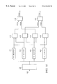
- FIG. 13 is a schematic block diagram of a dibit burst filter as shown in FIG. 12.
- FIG. 14 is a flow diagram of the processing steps carried out by the control system incorporating the PES demodulator of FIG. 12 .
- FIG. 2 there is illustrated a disk drive servo control system 110 constructed in accordance with the present invention.
- the disk drive includes a magnetic read/write head 112 mounted on a disk arm 114 that is moved across the surface 116 of a storage medium comprising a magnetic disk 118 by a servo assembly 120 .
- the read/write head reads changes in disk magnetic flux orientation recorded in tracks across the disk.
- FIG. 2 diagrammatically shows that the track is divided into sectors 124 having a servo information field 126 followed by a data field 128 .
- the servo control system controls movement of the disk arm 114 across the disk to move the read/write head 112 from track to track and to maintain the read/write head centered over a desired track.
- the read/write head moves across the disk surface 116 , the read/write head reads data and servo information and provides it to a demodulator 130 that asynchronously demodulates the servo information and squares the resulting signal to produce a position error signal (PES) that is used to control movement of the disk arm.
- PES position error signal
- the servo control system 110 eliminates phase induced error in the demodulated PES, benefits from sharing signal processing components with disk drive components for reading data from the data fields 128 , does not require a phase lock loop and a clock synchronization field in the servo information, and can effectively remove spurious artifacts from the demodulated servo information signal using digital techniques.
- the head When the read/write head 112 reads information from the track 122 , the head produces data and servo information signals provided over a head output line 132 to a preamplifier 134 .
- the preamplifier amplifies the data and servo information signals and provides the amplified signal to an automatic gain control (AGC) 136 that adjusts the gain applied to the signals to maintain signal amplitude within a range that is predetermined to simplify information processing, reduce noise, and improve system linearity.
- AGC automatic gain control
- the amplified signals from the AGC 136 are provided to an analog-to-digital converter 138 that asynchronously converts the signals in accordance with a sampling clock signal CK received over a sampling clock line 140 .
- the sampling clock signal CK is produced by a timing decoder 142 that receives a system clock signal over a system clock signal line 144 . If m is the number of samples to be sampled for each analog servo signal cycle, then the sampling clock signal CK should be m times the servo signal frequency. Thus, the frequency of the information signals recorded on a disk must be known for construction of the control system 110 .
- the digitized data and servo information signals are provided over a converter output line 146 to the demodulator 130 , which produces a position error signal (PES) that indicates the direction and extent of servo movement required to maintain the read/write head 112 centered about a track 122 .
- PES position error signal
- the PES is provided over a demodulator output line 148 to a conventional ramp stitching block 150 and then to a servo controller 152 that generates control signals provided to the servo 120 to move the disk arm 114 and read/write head 112 .
- the data information signal is provided to a host computer (not shown) configured to receive the data signal read from the track 122 .
- the automatic gain control (AGC) 136 and analog-to-digital converter 138 of the control system 110 are shared with the digital detection channel. That is, the AGC and converter are used both for detecting the servo information from the servo information field 126 of the track and the digital data from the data field 128 of the track. This reduces the number of components necessary for reading data from the disk and simplifies the overall construction of a disk drive servo control system.
- AGC automatic gain control
- analog-to-digital converter 138 of the control system 110 are shared with the digital detection channel. That is, the AGC and converter are used both for detecting the servo information from the servo information field 126 of the track and the digital data from the data field 128 of the track. This reduces the number of components necessary for reading data from the disk and simplifies the overall construction of a disk drive servo control system.
- FIG. 3 is a block diagram of a first preferred embodiment of the PES demodulator 130 constructed in accordance with the present invention.
- a digital filter 154 receives the digitized servo information signal over the converter output line 146 .
- the filter is implemented as a finite impulse response (FIR) filter circuit providing a harmonic notch equalizer filter with odd symmetry coefficients, known to those skilled in the art as a Hilbert Transform filter.
- FIR finite impulse response
- Such a filter eliminates signal asymmetry, shouldering, and baseline distortion, and other unwanted noise.
- the output of such a filter more closely resembles digital output to be expected from a sinusoidal input signal.
- an input signal to the filter 154 can be represented as a series of m digital values x 0 , x 1 , . . . , x m ⁇ 1 obtained per sampling interval of the analog-to-digital converter 138 via filter taps.
- the Hilbert Transform filter has coefficients denoted by the set (H 0 H 1 . . . H m ⁇ 1 ) for m samples per sampling interval.
- a set of Hilbert Transform coefficients for the FIR can be trained to perform the Hilbert Transform filtering for random phase sampling applications such as the asynchronous digital sampling controller of the present invention, in which the sampled input signal is phase non-coherent with the sampling clock signal.
- H i ( ⁇ 0.5 0 0.5) or ( ⁇ 1.0 0 1.0).
- the preferred embodiment includes a digital filter having coefficients defined by:
- the Hilbert Transform coefficients for eight samples per servo information signal cycle generally can be defined by:
- H i k ( ⁇ 1.0 ⁇ 1.41 ⁇ 1.0 0 1.0 1.41 1.0),
- FIG. 4 is a block diagram of the filter 154 showing the servo information signal values received over the converter output line 146 and provided to the filter by filter taps 156 , their multiplication by-filter coefficient blocks 158 , and their summation by a filter summer 160 to produce a filter output signal provided over a filter output line 162 .
- the filter response rejects the DC content and other odd and even harmonic contents of the signal samples and eliminates PES demodulation errors caused by random phase sampling processing. Furthermore, the filter response can be optimized to eliminate unwanted noise to improve the signal dynamic range.
- the output of the digital filter 154 comprising a series of m samples per servo information signal cycle, is provided over the filter output line 162 to a squarer 164 .
- the squarer receives the series of filtered values y n from the digital filter and squares each value.
- the squarer function is defined by:
- z n represents the output of the squarer.
- the squarer can be implemented either as a logic circuit or as a look-up table and provides an alternating quadrature data string.
- the output of the squarer is provided over a signal line 166 to a PES burst accumulator 168 that preferably is implemented as a running sum logic circuit.
- the PES burst accumulator adds all squared sample values z n and converts the sums to produce PES signals PESA, PESB, PESC, and PESD.
- the PES signals are defined by the following relationships:
- PESA ⁇ z n for burst intervals P 1 and P 2 ,
- PESD ⁇ z n for burst intervals P 1 and P 4 .
- the output signals of the accumulator 168 are provided over an output line 170 to a quadrature demodulation block 172 that subtracts the PES signals as follows to define primary and quadrature PES signals PESP and PESQ:
- the quadrature demodulation block 172 can be implemented in the demodulator 130 (FIG. 2) either as a logic circuit within the demodulator or as microprocessor firmware.
- the digital filter 154 , squarer 164 , burst accumulator 168 , and quadrature demodulation block 172 all operate in conjunction with the sample clock signal CK received over a timing line 140 from the timing decoder 142 .
- the output of the quadrature demodulation block is provided over the output line 148 of the demodulator 130 to the conventional ramp stitching block 150 .
- the ramp stitching block 150 discards the PESP and PESQ values beyond where the absolute value of PESP equals the absolute value of PESQ and “stitches” the useful sections of the PESP and PESQ values to form a linear PES ramp for each disk track.
- the PES ramp signal can be further linearized with a firmware-implemented square-root approximation or an appropriate look-up table.
- the ramp stitching block can be implemented in the controller 110 either as a logic circuit or as microprocessor firmware.
- the PES output signal from the ramp stitching block 150 is provided to the servo controller 152 to control the servo 120 and thereby control movement of the read/write head 112 across the disk 118 .
- the servo controller typically is implemented in microprocessor firmware of the disk controller 110 . As known to those skilled in the art, the servo controller uses PES ramp signal and servo Grey-code servo information data to compute track-following and track-seeking servo control signals that are provided to a digital-to-analog converter (not illustrated) to control voice-coil motors (VCM) for head positioning.
- VCM voice-coil motors
- the controller 110 substantially eliminates servo information signal conversion errors due to asynchronous sampling phase error, signal distortion produced by magneto-resistive (MR) or inductive heads, and phase jitter caused by high bandwidth components.
- the controller constructed in accordance with the invention is especially suited for high-density disk drive systems that must demodulate a PES from servo information fields of increased frequencies and reduced widths.
- the operation of the disk drive controller 110 illustrated in FIGS. 2, 3 , and 4 is represented by the steps of the flow diagram illustrated in FIG. 5 .
- the flow diagram steps can be implemented as hardware circuits and microprocessor firmware in the controller.
- the initial step illustrated by the first flow diagram box 202 is to sense the servo pattern transitions from the track of a disk.
- the controller pre-amplifies the analog servo information signal sensed from the disk at the flow diagram box numbered 204 .
- the controller provides the analog signal to the automatic gain control block and then, at the box numbered 208 , the signal is provided to the analog-to-digital converter.
- the digitized values x n are next provided to the digital filter with Hilbert Transform coefficients to produce the filtered digital signal values y n at the box numbered 210 .
- the values y n are provided to the squarer at the flow diagram box numbered 212 to produce the squared values z n .
- the squared values z n are provided to the burst accumulator to remove phase error.
- the z n values are added together, cycle by cycle. Thus, if four samples are taken per servo information signal cycle, and there are four cycles per burst, then sixteen terms will be added together to produce the PESA, PESB, PESC, and PESD terms.
- the PESA, PESB, PESC, and PESD terms are provided to the quadrature demodulation block to generate quadrature PES values PESP and PESQ according to the original burst pattern recorded on disk.
- the quadrature PESP and PESQ values are provided to the ramp stitching block to produce the PES ramp signal and then the output of the ramp stitching block is provided to the servo controller at the flow diagram box numbered 220 to move the disk arm and read/write head as indicated by the PES.
- FIG. 6 shows a block diagram of a second preferred embodiment of the PES demodulator 130 constructed in accordance with the present invention.
- a squarer is provided as a quadrature sum and squarer 182 and receives the output of the analog-to-digital converter 138 (FIG. 2) over the converter output line 146 for m samples per servo information signal cycle.
- the sampling frequency of four samples per servo information signal cycle is selected such that the consecutive sample points are 90° apart in terms of the servo signal phase.
- the sum and squarer 182 adds the sample magnitudes for like samples, squares them, and sums the terms for a burst interval. That is, rather than the simple squaring of the sample values described in connection with the squarer of the first embodiment illustrated in FIG. 4, the FIG. 6 embodiment includes a sum and squarer that produces output terms z n defined by:
- a PES burst accumulator 168 receives the squared terms over a signal line 166 and then provides the accumulated signal terms over a signal line 170 to a quadrature demodulation block 172 and then over the demodulator output line 148 to the ramp stitching block 150 .
- the sum and squarer 182 like the accumulator and demodulation block, operates in conjunction with the sample clock signal CK received over the timing line 140 from the timing decoder 142 .
- the operation of the disk drive controller 110 illustrated in FIG. 6 is represented by the steps of the flow diagram illustrated in FIG. 7 .
- the flow diagram steps can be implemented as hardware circuits and microprocessor firmware in the controller.
- the initial step illustrated by the first flow diagram box 302 is to sense the servo pattern transitions from the track of a disk.
- the controller pre-amplifies the analog servo information signal sensed from the disk at the flow diagram box numbered 304 .
- the controller provides the analog signal to the automatic gain control block and then, at the box numbered 308 , the signal is provided to the analog-to-digital converter.
- the digitized values X n are next provided to the sum and squarer of the demodulator to produce the output signal values z n at the box numbered 310 .
- the summed and squared values z n are provided to the burst accumulator to produce the PESA, PESB, PESC, and PESD terms.
- the PESA, PESB, PESC, and PESD terms are provided to the quadrature demodulation block to generate the quadrature PES values PESP and PESQ.
- the quadrature PESP and PESQ values are provided to the ramp stitching block to produce the PES ramp signal and then the output of the ramp stitching block is provided to the servo controller at the flow diagram box numbered 318 to move the disk arm and read/write head as indicated by the PES.
- FIG. 12 is a block diagram of a third preferred embodiment of the PES demodulator 130 constructed in accordance with the present invention.
- the invention utilizes the fact that paired magnetic transitions within the servo burst, as shown in FIG. 1, produce a unique dibit servo signal.
- the detection of signal energy is obtained by correlating the received signal in discrete time with a dibit coherent filtering coefficient which is defined based on the formation of the dibit signal.
- a dibit burst filter 1202 receives the digitized servo information signal over the converter output line 146 .
- the filter 1202 is implemented as a fixed-tap finite impulse response (FIR) filter circuit providing a harmonic notch equalizer filter with odd symmetry coefficients, known to those skilled in the art as a Hilbert Transform filter.
- the filter 1202 commonly referred to in the art as a “matched” filter, matches the signal energy of the dibit signal and eliminates signal asymmetry, shouldering, and baseline distortion, DC drifts, strong even harmonic contents due to MR read, and other unwanted noise and harmonics.
- an input signal to the filter 1202 can be represented as a series of m digital values y 0 , y 1 , . . . , y m ⁇ 1 obtained per sampling interval of the analog-to-digital converter 138 via filter taps.
- the preferred filter tap weights are “1, 1, 0, 0, ⁇ 1, ⁇ 1” when the analog-to-digital circuit converts the analog signal with a sampling clock frequency which is 8 times higher than the fundamental signal frequency.
- the filter 1202 operates as a matched filter for filtering of the digitized samples and to correlate the main energy of the dibit signal.
- FIG. 13 A preferred realization of the dibit burst filter 1202 is shown in FIG. 13 .
- the filter's configuration provides a high frequency operation without using a standard multiplication and accumulation filter circuit structure known to those skilled in the art of digital filtering.
- the filter comprises two three-tap Hilbert transform filters connected in a parallel configuration.
- a signal is received by registers 1302 , 1304 , 1306 , and 1308 from the analog-to-digital converter through signal input line 146 .
- the sampling clocks provided on the system clock signal line 144 and a signal line 145 shown in FIG. 12, are 90 degrees out of phase with respect to the sample clock signal CK received over line 140 .
- Sampling clocks 144 and 145 characteristically display one-half of the original frequency of the line 140 .
- the signal provided on line 146 is also passed through inverters 1310 and 1312 and transferred to adders 1314 and 1316 .
- the adders 1314 and 1316 also receive a signal output from the registers 1304 and 1308 , respectively.
- the adders sum the signals received, perform a two's-complement function by adding of an “I” with 1320 and 1322 , and then transfer an output signal to adder 1318 .
- the sums input from adders 1314 and 1316 are then summed and output via filter line 1201 to the burst accumulator 1204 .
- two three-tap filters are discussed, the inventors have found that the invention may also be practiced using a six tap or eight tap filter.
- the burst accumulator 1204 receives signals from the dibit burst filter 1202 .
- the burst accumulator is preferably implemented as a running sum logic circuit.
- the burst accumulator 1204 adds the absolute values of the output samples corresponding to each servo burst interval and converts the sums to produce PES signals PESA, PESB, PESC, and PESD.
- the PES signals are defined as follows:
- PESA ⁇
- PESD ⁇
- the burst accumulator 1204 output signals are provided to a quardrature demodulator 1206 (see FIG. 12) that subtracts the PES signals to determine the primary, and secondary or quadrature, PES signals PESP and PESQ as follows:
- the quadrature demodulator 1206 can be implemented as either a logic circuit or as microprocessor firmware.
- a threshold detector 1208 which received the output from the dibit filter 1202 is formed with a threshold detection circuit using the received filter output samples. Threshold detection is accomplished with a predefined level for comparison to determine binary one or binary zero for encoding of pulse code bits for track address.
- a partial response finite impulse response (PR-FIR) filter 1210 shown in FIG. 12 receives a data signal from the analog-to-digital converter 138 .
- the filter consists of coefficient registers, data delay registers and multiplier/accumulation circuits.
- the PR-FIR filter 1210 output data signal is transferred to the data detector 1212 where the data signal is processed and then sent to the host computer (not shown) for further processing.
- the dibit burst filter 1202 , burst accumulator 1204 , quadrature demodulator 1206 , threshold detector 1208 , PR-FIR filter 1210 , and data detector 1212 all operate in conjunction with the sample clock signal received over the timing line 140 .
- the clock pulse is relatively synchronous, or phase correlated, with the servo signal.
- the outputs from the quadrature demodulator 1206 and the threshold detector 1208 are provided over output line 148 of the demodulator 130 to the conventional ramp stitching block 150 shown in FIG. 2 .
- the relatively synchronous clock pulses, provided on lines 140 , 144 and 145 , with respect to the servo analog signal, are phase-adjusted and produced by a timing decoder 1214 , which receives the system clock pulse 141 and the track address line 1209 along with the sector pulse feedback via pulse line 1211 from the threshold detector.
- the sector pulse feedback is used as a timing reference for the phase adjustment of the clock pulse lines.
- the operation of the disk drive controller 110 utilizing the PES demodulator 130 shown in FIG. 12 is represented by the steps of the flow diagram illustrated in FIG. 14 .
- the flow diagram steps can be implemented as hardware circuits and/or microprocessor firmware in the controller 110 .
- the steps begin in box 1401 with the initial step illustrated by the flow diagram box 1402 where the data and servo pattern transition signals are sensed from the track of a disk.
- the controller 110 pre-amplifies the analog signals sensed from the disk at the flow diagram box numbered 1404 .
- the controller provides the analog signals to the automatic gain control filter 136 and then, at the box numbered 1408 , the signals are provided to the analog-to-digital converter.
- the digitized servo information signal values x n are next provided to the dibit burst filter 1202 at box 1416 to produce the output signal values y n
- the data signal is provided to the PR-FIR filter 1210 at the box numbered 1410 .
- the PR-FIR filter 1210 sends a data signal to the data detector in box 1412 and data signal is output in box 1414 .
- the read-back data is supplied to the host computer via the host computer for processing interface.
- the data process ends in box 1434 when the data is received by the host computer for further processing.
- the output servo information signal values y n provided from the dibit burst filter 1202 at box 1416 are provided to the threshold detector at box 1426 and the burst accumulator at box 1418 .
- the values y n are provided to the burst accumulator to produce the PESA, PESB, PESC, and PESD terms.
- the PESA, PESB, PESC, and PESD terms are provided to the quadrature demodulation block to generate the quadrature PES values PESP and PESQ at box 1424 .
- the output signal provided to the threshold detector at box 1426 is used in box 1428 to generate a track address and sector pulse signal.
- the track address and sector signal is provided to the ramp stitching block, along with the quadrature PESP and PESQ values at the flow diagram box numbered 1430 , to produce the PES ramp signal, after the timing pulse feedback is sent to the timing decoder 1214 .
- the pulse feedback may include the system clock pulse and the sector pulse feedback.
- the output of the ramp stitching block is provided to the servo controller at the flow diagram box numbered 1432 to move the disk arm and read/write head as indicated by the PES. The process ends at box 1434 .
- a servo pattern in accordance with the present invention preferably comprises a “split burst” pattern having transitions that do not extend across the full width of a track. In this way, transitions from adjacent passes of a recording head do not need to be aligned to produce the pattern. Rather, the split burst pattern is recorded such that every flux transition is formed by a single pass of a magnetic head.
- FIG. 8 is a representation of a first split burst servo pattern constructed in accordance with the present invention, recorded on a disk.
- FIG. 8 shows a disk 10 and four tracks 312 , 314 , 316 , and 318 across the disk surface.
- the illustrated servo burst pattern comprises eight half-width transitions 320 per burst.
- the transitions define a pattern having four repeating groups P 1 , P 2 , P 3 , and P 4 per sector, each of which can be recorded in a single pass of a recording head. Because the transitions are only one-half track wide, it is not necessary to align adjacent transitions so that they appear to be recorded by a head that extends across the full track, as is necessary with the conventional FIG. 1 servo pattern. Therefore, there is no alignment problem with the pattern illustrated in FIG. 8 .
- the servo pattern must provide linearity across the full track width. Therefore, the transitions 320 of the FIG. 8 split burst servo information pattern are individually measured and combined arithmetically to determine the equivalent amplitudes of the bursts across the track.
- an A-burst group of transitions comprises a group of four transitions P 1 2 comprising the last four transitions of the P 1 group extending across a second half of a track 312 and a group of four transitions P 2 1 comprising the first four transitions of the P 2 group extending across the first half of the next track. It should be clear that, when the disk 10 rotates, the P 1 2 group of transitions is followed in the disk radial direction by the P 2 1 group of transitions.
- a B-burst group of transitions comprises a group of four transitions P 3 2 comprising the last four transitions of the P 3 group extending across a second half of a track 314 and a group of four transitions P 4 1 comprising the first four transitions of the P 4 group extending across the first half of the next track.
- the B-burst signal is provided by the sum of the P 3 2 and P 4 1 groups.
- a C-burst signal is defined by the sum of P 2 2 comprising the last four transitions of the P 2 group and of P 3 1 comprising the first four transitions of the P 3 group.
- a D-burst signal is defined by the sum of P 4 2 comprising the last four transitions of the P 4 group and of P 1 1 comprising the first four transitions of a P 1 group from the same track 316 .
- the A-burst, B-burst, C-burst, and D-burst signals define PES component signals defined by:
- PESA ⁇ (P 1 i +P 2 i ),
- PESD ⁇ (P 4 i +P 1 i ),
- P 1 i , P 2 i , P 3 i , and P 4 i are preprocessed burst samples (that is, digitized samples of the P 1 , P 2 , P 3 , and P 4 transitions that have been squared) as defined above.
- the primary and quadrature components of the PES then can be generated by the PES demodulation block as follows:
- the transitions 320 of the split burst servo information pattern can be combined arithmetically in other schemes to determine the equivalent amplitudes of the bursts across the track.
- FIG. 9 illustrates a second scheme of combining the groups of the split burst servo pattern to provide linearity and a quadrature PES.
- FIG. 9 shows a disk 10 and four tracks 312 , 314 , 316 , and 318 across the disk surface.
- the illustrated pattern comprises eight half-width transitions 320 per burst comprising four groups P 1 , P 2 , P 3 , and P 4 per cycle. Again, because the transitions are only one-half track wide, it is not necessary to align adjacent transitions so that they appear to be recorded by a head that extends across the full track and the alignment noise problem is eliminated.
- a first group of eight half-width transitions in the first track 312 comprising a P 1 group and a second group of eight transitions in the third track 316 comprising another P 1 group define a P 1 -burst PES component signal.
- a group of eight half-width transitions in the second track 314 comprising a P 2 group immediately following the first P 1 group and a second group of eight half-width transitions in the fourth track 318 comprising a second P 2 group immediately following the second P 1 group define a P 2 -burst PES component signal.
- a P 3 group of eight half-width transitions from the second and fourth tracks 314 , 318 define a P 3 -burst PES component signal and a P 4 group of eight half-width transitions from the first and third tracks define a P 4 -burst PES component signal, as illustrated in FIG. 9 .
- the component signals can be defined by:
- PESA ⁇ (P 1 i +P 2 i ),
- PESD ⁇ (P 4 i +P 1 i ),
- P 1 i , P 2 i , P 3 i , and P 4 i are digitized samples of the P 1 , P 2 , P 3 , and P 4 transitions that have been read from the respective tracks, as defined above, and then squared.
- the primary and quadrature components of the PES then can be generated by the PES demodulation block as follows:
- split burst servo pattern and combining schemes illustrated in FIGS. 8 and 9 can be used with conventional PES demodulators that combine the PES component signals as described above, as well as with the digital disk drive controller of the present invention.
- the split burst servo pattern eliminates the PES errors associated with alignment problems experienced with conventional servo burst patterns.
- FIG. 10 shows a block diagram of the PES burst accumulator 168 and quadrature demodulation block 172 of the disk controller 110 for use with demodulation of the servo patterns illustrated above.
- the burst accumulator receives the preprocessed signals and provides them to one of four registers 402 , 404 , 406 , and 408 corresponding to the P 1 , P 2 , P 3 , and P 4 component signals, respectively.
- a group of four adders 410 , 412 , 414 , and 416 provides the summing of the proper signals to provide the PESA, PESB, PESC, and PESD burst components, respectively, as defined above.
- two subtractors 418 and 420 receive the appropriate burst components and provide the proper subtraction to provide the signals PESP and PESQ, respectively, as defined above.
- FIG. 10 shows the signals PESP and PESQ on separate output lines, it is to be understood that in the preferred embodiment the PESP and PESQ signals are alternately provided on the PES burst accumulator output line 170 .
- each of the repeating groups is comprised of eight half-width magnetic flux transitions, represented by a vertical bar 320 , each of which can be recorded in a single pass of a recording head.
- the T 1 group of the first track 312 is radially succeeded by the T 3 group of the second track. That is, the when the disk 10 rotates, the T 3 group of transitions next follows the T 1 group in the disk radial direction.
- the T 3 group of the first track is radially succeeded by the T 2 group of the next adjacent second track 314 .
- the T 2 group is radially succeeded by the T 4 group of the next track.
- a T 1 group of the next track 316 radially follows the T 4 group of the same track.
- PESA ⁇ (T 1 i +T 3 i ),
- T 1 i , T 2 i , T 3 i , and T 4 i are preprocessed, digitized samples of the T 1 , T 2 , T 3 , and T 4 transitions that have been squared as described above.
- the primary and quadrature components of the PES then can be generated by the PES demodulation block 172 (FIGS. 3 and 6) as follows:
- the present invention described above provides a disk drive servo control system that eliminates phase error in the demodulated PES, shares components with the digital data processing elements of the disk drive and achieves greater efficiency, does not require a phase lock loop and provides simpler circuit design, does not require a clock synchronization field in the servo information and thereby increases disk data capacity, and makes effective use of digital signal processing techniques for accurate PES demodulation.
- the split burst servo information pattern eliminates error due to misalignment of transition bursts across a track width and contributes to more accurate read/write head positioning.
Abstract
Description
Claims (23)
Priority Applications (1)
| Application Number | Priority Date | Filing Date | Title |
|---|---|---|---|
| US08/938,267 US6324030B1 (en) | 1995-05-02 | 1997-09-26 | Digital pes demodulation for a disk drive servo control system using synchronous digital sampling |
Applications Claiming Priority (3)
| Application Number | Priority Date | Filing Date | Title |
|---|---|---|---|
| US43262795A | 1995-05-02 | 1995-05-02 | |
| US08/918,959 US5818659A (en) | 1995-05-02 | 1997-08-26 | Quadrature servo pattern disk providing asynchronous digital PES |
| US08/938,267 US6324030B1 (en) | 1995-05-02 | 1997-09-26 | Digital pes demodulation for a disk drive servo control system using synchronous digital sampling |
Related Parent Applications (1)
| Application Number | Title | Priority Date | Filing Date |
|---|---|---|---|
| US08/918,959 Continuation-In-Part US5818659A (en) | 1995-05-02 | 1997-08-26 | Quadrature servo pattern disk providing asynchronous digital PES |
Publications (1)
| Publication Number | Publication Date |
|---|---|
| US6324030B1 true US6324030B1 (en) | 2001-11-27 |
Family
ID=27029579
Family Applications (1)
| Application Number | Title | Priority Date | Filing Date |
|---|---|---|---|
| US08/938,267 Expired - Lifetime US6324030B1 (en) | 1995-05-02 | 1997-09-26 | Digital pes demodulation for a disk drive servo control system using synchronous digital sampling |
Country Status (1)
| Country | Link |
|---|---|
| US (1) | US6324030B1 (en) |
Cited By (21)
| Publication number | Priority date | Publication date | Assignee | Title |
|---|---|---|---|---|
| US20030026035A1 (en) * | 2001-05-29 | 2003-02-06 | International Business Machines Corporation | Method and apparatus for improved PES demodulation in the presence of thermal asperities |
| US20030026016A1 (en) * | 2001-06-28 | 2003-02-06 | Stmicroelectronics, Inc. | Circuit and method for demodulating a servo position burst |
| US20030048560A1 (en) * | 2001-06-28 | 2003-03-13 | Stmicroelectronics, Inc. | Data-storage disk having few or no spin-up wedges and method for writing servo wedges onto the disk |
| US6556941B2 (en) * | 2000-10-27 | 2003-04-29 | Ade Corporation | Separation of periodic and non-periodic signal components |
| US20030169665A1 (en) * | 2000-10-31 | 2003-09-11 | Matsushita Electric Industrial Co., Ltd. | Equalizer and PRML detector |
| US6721243B2 (en) * | 1998-08-29 | 2004-04-13 | Samsung Electronics Co., Ltd. | Method for detecting servo error, apparatus therefor, disk which maintains quality of servo error signal, method of controlling servo of disk recording/reproducing apparatus, method of detecting tracking error, and method of detecting tilt error |
| US20040212525A1 (en) * | 2003-03-28 | 2004-10-28 | Ess Technology, Inc. | Audio digital to analog converter with harmonic suppression |
| US7002761B1 (en) * | 2003-03-27 | 2006-02-21 | Marvell International Ltd. | Demodulation compensation for spiral servo tracks in hard disk drives |
| US7158333B1 (en) | 2003-04-03 | 2007-01-02 | Marvell International Ltd. | Up-sampled filtering for servo demodulation |
| US7209312B1 (en) * | 2004-07-15 | 2007-04-24 | Marvell International Ltd. | Self-servo-write using ramp-tracks |
| US20070206319A1 (en) * | 2006-03-06 | 2007-09-06 | Marvell International Ltd. | Method for measuring actuator velocity during self-servo-write |
| US20080165444A1 (en) * | 2007-01-05 | 2008-07-10 | Broadcom Corporation, A California Corporation | Baseline popping noise detection circuit |
| US20100128386A1 (en) * | 2008-11-25 | 2010-05-27 | Seagate Technology Llc | Reducing effect of frequency acquisition error in a position error signal responsive to split servo burst patterns |
| US7751144B1 (en) | 2004-07-15 | 2010-07-06 | Marvell International Ltd. | Self-servo-write using ramp-tracks |
| US7773334B1 (en) | 2006-12-06 | 2010-08-10 | Marvell International Ltd. | Single-pass spiral self-servo-write |
| US7830630B2 (en) | 2001-06-28 | 2010-11-09 | Stmicroelectronics, Inc. | Circuit and method for detecting the phase of a servo signal |
| US20100302676A1 (en) * | 2009-05-27 | 2010-12-02 | Mustafa Can Ozturk | Circuits that use a postamble signal to determine phase and frequency errors in the acquisition of a preamble signal |
| US8625231B1 (en) * | 2012-11-08 | 2014-01-07 | HGST Netherlands B.V. | Adjusting VGA analog gain for misaligned servo sectors in a disk drive |
| US20170131335A1 (en) * | 2015-11-09 | 2017-05-11 | Thomas G. Pratt | Coherent signal analyzer |
| US10280787B2 (en) | 2015-11-09 | 2019-05-07 | University Of Notre Dame Du Lac | Monitoring rotating machinery using radio frequency probes |
| US11830524B1 (en) | 2022-06-13 | 2023-11-28 | Western Digital Technologies, Inc | Data storage device with split burst servo pattern |
Citations (10)
| Publication number | Priority date | Publication date | Assignee | Title |
|---|---|---|---|---|
| WO1990013113A1 (en) | 1989-04-27 | 1990-11-01 | Siemens Aktiengesellschaft | Process for positioning a magnetic-disc memory, and device for carrying out the process |
| US5255131A (en) | 1992-08-13 | 1993-10-19 | International Business Machines Corporation | Asynchronous servo identification/address mark detection for PRML disk drive ssytem |
| US5319502A (en) * | 1992-01-10 | 1994-06-07 | International Business Machines Corporation | System and method for employing buried servos within a magnetic recording medium |
| US5442498A (en) | 1993-11-08 | 1995-08-15 | International Business Machines Corporation | Asynchronous track code encodement and detection for disk drive servo control system |
| US5444578A (en) | 1992-12-28 | 1995-08-22 | Mitsubishi Denki Kabushiki Kaisha | Magnetic reproduction circuit having variable amplification for correction |
| US5541784A (en) | 1992-11-10 | 1996-07-30 | Daniel F. Cribbs | Bootstrap method for writing servo tracks on a disk drive |
| US5576906A (en) * | 1994-10-11 | 1996-11-19 | Quantum Corporation | Synchronous detection of concurrent servo bursts for fine head position in disk drive |
| US5774298A (en) * | 1993-11-23 | 1998-06-30 | International Business Machines Corporation | Asynchronous digital PES demodulation disk drive servo control system |
| US5818659A (en) * | 1995-05-02 | 1998-10-06 | International Business Machines Corporation | Quadrature servo pattern disk providing asynchronous digital PES |
| US6023389A (en) * | 1997-06-18 | 2000-02-08 | International Business Machines Corporation | Method and apparatus for writing servo bursts with compensation for erase bands in a direct access storage device |
-
1997
- 1997-09-26 US US08/938,267 patent/US6324030B1/en not_active Expired - Lifetime
Patent Citations (10)
| Publication number | Priority date | Publication date | Assignee | Title |
|---|---|---|---|---|
| WO1990013113A1 (en) | 1989-04-27 | 1990-11-01 | Siemens Aktiengesellschaft | Process for positioning a magnetic-disc memory, and device for carrying out the process |
| US5319502A (en) * | 1992-01-10 | 1994-06-07 | International Business Machines Corporation | System and method for employing buried servos within a magnetic recording medium |
| US5255131A (en) | 1992-08-13 | 1993-10-19 | International Business Machines Corporation | Asynchronous servo identification/address mark detection for PRML disk drive ssytem |
| US5541784A (en) | 1992-11-10 | 1996-07-30 | Daniel F. Cribbs | Bootstrap method for writing servo tracks on a disk drive |
| US5444578A (en) | 1992-12-28 | 1995-08-22 | Mitsubishi Denki Kabushiki Kaisha | Magnetic reproduction circuit having variable amplification for correction |
| US5442498A (en) | 1993-11-08 | 1995-08-15 | International Business Machines Corporation | Asynchronous track code encodement and detection for disk drive servo control system |
| US5774298A (en) * | 1993-11-23 | 1998-06-30 | International Business Machines Corporation | Asynchronous digital PES demodulation disk drive servo control system |
| US5576906A (en) * | 1994-10-11 | 1996-11-19 | Quantum Corporation | Synchronous detection of concurrent servo bursts for fine head position in disk drive |
| US5818659A (en) * | 1995-05-02 | 1998-10-06 | International Business Machines Corporation | Quadrature servo pattern disk providing asynchronous digital PES |
| US6023389A (en) * | 1997-06-18 | 2000-02-08 | International Business Machines Corporation | Method and apparatus for writing servo bursts with compensation for erase bands in a direct access storage device |
Cited By (51)
| Publication number | Priority date | Publication date | Assignee | Title |
|---|---|---|---|---|
| US6721243B2 (en) * | 1998-08-29 | 2004-04-13 | Samsung Electronics Co., Ltd. | Method for detecting servo error, apparatus therefor, disk which maintains quality of servo error signal, method of controlling servo of disk recording/reproducing apparatus, method of detecting tracking error, and method of detecting tilt error |
| US7319643B2 (en) | 1998-08-29 | 2008-01-15 | Samsung Electronics Co., Ltd. | Method for detecting servo error, apparatus therefor, disk which maintains quality of servo error signal, method of controlling servo of disk recording/reproducing apparatus, method of detecting tracking error, and method of detecting tilt error |
| US7590034B2 (en) | 1998-08-29 | 2009-09-15 | Samsung Electronics Co., Ltd. | Method for detecting servo error, apparatus therefor, disk which maintains quality of servo error signal, method of controlling servo of disk recording/reproducing apparatus, method of detecting tracking error, and method of detecting tilt error |
| US20060092789A1 (en) * | 1998-08-29 | 2006-05-04 | Samsung Electronics Co., Ltd. | Method for detecting servo error, apparatus therefor, disk which maintains quality of servo error signal, method of controlling servo of disk recording/reproducing apparatus, method of detecting tracking error, and method of detecting tilt error |
| US20080068957A1 (en) * | 1998-08-29 | 2008-03-20 | Samsung Electronics Co., Ltd | Method for detecting servo error, apparatus therefor, disk which maintains quality of servo error signal, method of controlling servo of disk recording/reproducing apparatus, method of detecting tracking error, and method of detecting tilt error |
| US6556941B2 (en) * | 2000-10-27 | 2003-04-29 | Ade Corporation | Separation of periodic and non-periodic signal components |
| US6678230B2 (en) * | 2000-10-31 | 2004-01-13 | Matsushita Electric Industrial Co., Ltd. | Waveform equalizer for a reproduction signal obtained by reproducing marks and non-marks recorded on a recording medium |
| US20040151097A1 (en) * | 2000-10-31 | 2004-08-05 | Matsushita Electric Industrial Co., Ltd. | Waveform equalizer for a reproduction signal obtained by reproducing marks and non-marks recorded on a recording medium |
| US20030169665A1 (en) * | 2000-10-31 | 2003-09-11 | Matsushita Electric Industrial Co., Ltd. | Equalizer and PRML detector |
| US6934233B2 (en) | 2000-10-31 | 2005-08-23 | Matsushita Electric Industrial Co., Ltd. | Waveform equalizer for a reproduction signal obtained by reproducing marks and non-marks recorded on a recording medium |
| US6937551B2 (en) | 2000-10-31 | 2005-08-30 | Matsushita Electric Industrial Co., Ltd. | PRML detector having a viterbi decoder outputting temporary judgement results |
| US6687080B2 (en) * | 2001-05-29 | 2004-02-03 | Hitachi Global Storage Technologies Netherlands B.V. | Method and apparatus for improved PES demodulation in the presence of thermal asperities |
| US20030026035A1 (en) * | 2001-05-29 | 2003-02-06 | International Business Machines Corporation | Method and apparatus for improved PES demodulation in the presence of thermal asperities |
| US7839594B2 (en) | 2001-06-28 | 2010-11-23 | Stmicroelectronics, Inc. | Data-storage disk having few or no spin-up wedges and method for writing servo wedges onto the disk |
| US20030048560A1 (en) * | 2001-06-28 | 2003-03-13 | Stmicroelectronics, Inc. | Data-storage disk having few or no spin-up wedges and method for writing servo wedges onto the disk |
| US7830630B2 (en) | 2001-06-28 | 2010-11-09 | Stmicroelectronics, Inc. | Circuit and method for detecting the phase of a servo signal |
| US20110002061A1 (en) * | 2001-06-28 | 2011-01-06 | Stmicroelectronics, Inc. | Circuit and method for detecting the phase of a servo signal |
| US20030026016A1 (en) * | 2001-06-28 | 2003-02-06 | Stmicroelectronics, Inc. | Circuit and method for demodulating a servo position burst |
| US8379340B2 (en) | 2001-06-28 | 2013-02-19 | Stmicroelectronics, Inc. | Circuit and method for detecting the phase of a servo signal |
| US7463437B1 (en) | 2003-03-27 | 2008-12-09 | Marvell International Ltd. | Demodulation compensation for spiral servo tracks in hard disk drives |
| US7307806B1 (en) | 2003-03-27 | 2007-12-11 | Marvell International Ltd. | Demodulation compensation for spiral servo tracks in hard disk drives |
| US7002761B1 (en) * | 2003-03-27 | 2006-02-21 | Marvell International Ltd. | Demodulation compensation for spiral servo tracks in hard disk drives |
| US7715134B1 (en) | 2003-03-27 | 2010-05-11 | Marvell International Ltd. | Demodulation compensation for spiral servo tracks in hard disk drives |
| US20050219104A1 (en) * | 2003-03-28 | 2005-10-06 | Ess Technology, Inc. | Audio digital to analog converter with harmonic suppression |
| US6987475B2 (en) * | 2003-03-28 | 2006-01-17 | Ess Technology Inc. | Audio digital to analog converter with harmonic suppression |
| US20040212525A1 (en) * | 2003-03-28 | 2004-10-28 | Ess Technology, Inc. | Audio digital to analog converter with harmonic suppression |
| US6897795B2 (en) * | 2003-03-28 | 2005-05-24 | Ess Technology | Audio digital to analog converter with harmonic suppression |
| US7583469B1 (en) | 2003-04-03 | 2009-09-01 | Marvell International Ltd. | Up-sampled filtering for servo demodulation |
| US7158333B1 (en) | 2003-04-03 | 2007-01-02 | Marvell International Ltd. | Up-sampled filtering for servo demodulation |
| US7764458B1 (en) | 2003-04-03 | 2010-07-27 | Marvell International Ltd. | Up-sampled filtering for servo demodulation |
| US7209312B1 (en) * | 2004-07-15 | 2007-04-24 | Marvell International Ltd. | Self-servo-write using ramp-tracks |
| US7522370B1 (en) | 2004-07-15 | 2009-04-21 | Marvell International Ltd. | Self-servo-write using ramp-tracks |
| US8184393B1 (en) | 2004-07-15 | 2012-05-22 | Marvell International Ltd. | Self-servo-write using ramp-tracks |
| US8514510B1 (en) | 2004-07-15 | 2013-08-20 | Marvell International Ltd. | Self-servo-write using ramp-tracks |
| US7751144B1 (en) | 2004-07-15 | 2010-07-06 | Marvell International Ltd. | Self-servo-write using ramp-tracks |
| US7852598B1 (en) | 2004-07-15 | 2010-12-14 | Marvell International Ltd. | Self-servo-write using sloped tracks written using a calibrated current profile |
| US7349171B2 (en) | 2006-03-06 | 2008-03-25 | Marvell World Trade Ltd. | Method for measuring actuator velocity during self-servo-write |
| US7567404B1 (en) | 2006-03-06 | 2009-07-28 | Marvell World Trade Ltd. | Method for measuring actuator velocity during self-servo-write |
| US20070206319A1 (en) * | 2006-03-06 | 2007-09-06 | Marvell International Ltd. | Method for measuring actuator velocity during self-servo-write |
| US7773334B1 (en) | 2006-12-06 | 2010-08-10 | Marvell International Ltd. | Single-pass spiral self-servo-write |
| US8031428B1 (en) | 2006-12-06 | 2011-10-04 | Marvell International Ltd. | Single-pass spiral self-servo-write |
| US20080165444A1 (en) * | 2007-01-05 | 2008-07-10 | Broadcom Corporation, A California Corporation | Baseline popping noise detection circuit |
| US9514775B2 (en) | 2008-11-25 | 2016-12-06 | Seagate Technology Llc | Reducing effect of frequency acquisition error in a position error signal responsive to split servo burst patterns |
| US20100128386A1 (en) * | 2008-11-25 | 2010-05-27 | Seagate Technology Llc | Reducing effect of frequency acquisition error in a position error signal responsive to split servo burst patterns |
| US7995304B2 (en) | 2009-05-27 | 2011-08-09 | Seagate Technology Llc | Circuits that use a postamble signal to determine phase and frequency errors in the acquisition of a preamble signal |
| US20100302676A1 (en) * | 2009-05-27 | 2010-12-02 | Mustafa Can Ozturk | Circuits that use a postamble signal to determine phase and frequency errors in the acquisition of a preamble signal |
| US8625231B1 (en) * | 2012-11-08 | 2014-01-07 | HGST Netherlands B.V. | Adjusting VGA analog gain for misaligned servo sectors in a disk drive |
| US20170131335A1 (en) * | 2015-11-09 | 2017-05-11 | Thomas G. Pratt | Coherent signal analyzer |
| US10280787B2 (en) | 2015-11-09 | 2019-05-07 | University Of Notre Dame Du Lac | Monitoring rotating machinery using radio frequency probes |
| US10605841B2 (en) * | 2015-11-09 | 2020-03-31 | University Of Notre Dame Du Lac | Coherent signal analyzer |
| US11830524B1 (en) | 2022-06-13 | 2023-11-28 | Western Digital Technologies, Inc | Data storage device with split burst servo pattern |
Similar Documents
| Publication | Publication Date | Title |
|---|---|---|
| US5774298A (en) | Asynchronous digital PES demodulation disk drive servo control system | |
| US6324030B1 (en) | Digital pes demodulation for a disk drive servo control system using synchronous digital sampling | |
| US5818659A (en) | Quadrature servo pattern disk providing asynchronous digital PES | |
| US5862005A (en) | Synchronous detection of wide bi-phase coded servo information for disk drive | |
| US6144513A (en) | Detecting servo data and servo bursts from discrete time samples of an analog read signal in a sampled amplitude read channel | |
| KR100570558B1 (en) | Synchronous digital demodulator with integrated read and servo channels | |
| US4549232A (en) | Phase modulated servo system | |
| EP0803158B1 (en) | Wide biphase digital servo information, detection, and estimation for disk drive using viterbi detection | |
| US5576906A (en) | Synchronous detection of concurrent servo bursts for fine head position in disk drive | |
| US6108151A (en) | Sampled amplitude read channel for reading user data and embedded servo data from a magnetic medium | |
| US5442498A (en) | Asynchronous track code encodement and detection for disk drive servo control system | |
| US5615065A (en) | Phase-compensated servo pattern and position error-sensing detector | |
| US6025970A (en) | Digital demodulation of a complementary two-frequency servo PES pattern | |
| US6856480B2 (en) | Phase tolerant servo gray code detector | |
| US6233715B1 (en) | Synchronous servo gray code detector using a PR4 matched filter | |
| JPH02168472A (en) | Demodulator for magnetic disk device | |
| JPS6369067A (en) | Reproducing system for digital magnetic recording information |
Legal Events
| Date | Code | Title | Description |
|---|---|---|---|
| AS | Assignment |
Owner name: INTERNATIONAL BUSINESS MACHINES CORPORATION, NEW Y Free format text: ASSIGNMENT OF ASSIGNORS INTEREST;ASSIGNORS:CHEUNG, WAYNE LEUNG;NGUYEN, THINH HUU;WANG, CHORNG-KUANG;REEL/FRAME:008735/0912;SIGNING DATES FROM 19970908 TO 19970915 |
|
| STCF | Information on status: patent grant |
Free format text: PATENTED CASE |
|
| AS | Assignment |
Owner name: MARIANA HDD B.V., NETHERLANDS Free format text: ASSIGNMENT OF ASSIGNORS INTEREST;ASSIGNOR:INTERNATIONAL BUSINESS MACHINES CORPORATION;REEL/FRAME:013663/0348 Effective date: 20021231 |
|
| AS | Assignment |
Owner name: HITACHI GLOBAL STORAGE TECHNOLOGIES NETHERLANDS B. Free format text: CHANGE OF NAME;ASSIGNOR:MARIANA HDD B.V.;REEL/FRAME:013746/0146 Effective date: 20021231 |
|
| CC | Certificate of correction | ||
| FEPP | Fee payment procedure |
Free format text: PAYOR NUMBER ASSIGNED (ORIGINAL EVENT CODE: ASPN); ENTITY STATUS OF PATENT OWNER: LARGE ENTITY |
|
| FPAY | Fee payment |
Year of fee payment: 4 |
|
| FPAY | Fee payment |
Year of fee payment: 8 |
|
| AS | Assignment |
Owner name: HGST, NETHERLANDS B.V., NETHERLANDS Free format text: CHANGE OF NAME;ASSIGNOR:HGST, NETHERLANDS B.V.;REEL/FRAME:029341/0777 Effective date: 20120723 Owner name: HGST NETHERLANDS B.V., NETHERLANDS Free format text: CHANGE OF NAME;ASSIGNOR:HITACHI GLOBAL STORAGE TECHNOLOGIES NETHERLANDS B.V.;REEL/FRAME:029341/0777 Effective date: 20120723 |
|
| FPAY | Fee payment |
Year of fee payment: 12 |
|
| AS | Assignment |
Owner name: WESTERN DIGITAL TECHNOLOGIES, INC., CALIFORNIA Free format text: ASSIGNMENT OF ASSIGNORS INTEREST;ASSIGNOR:HGST NETHERLANDS B.V.;REEL/FRAME:040818/0551 Effective date: 20160831 |