US6429994B1 - Method and apparatus for providing servo gain linearization for a magneto-resistive head - Google Patents
Method and apparatus for providing servo gain linearization for a magneto-resistive head Download PDFInfo
- Publication number
- US6429994B1 US6429994B1 US09/134,277 US13427798A US6429994B1 US 6429994 B1 US6429994 B1 US 6429994B1 US 13427798 A US13427798 A US 13427798A US 6429994 B1 US6429994 B1 US 6429994B1
- Authority
- US
- United States
- Prior art keywords
- servo
- bits
- bit
- track
- tracks
- Prior art date
- Legal status (The legal status is an assumption and is not a legal conclusion. Google has not performed a legal analysis and makes no representation as to the accuracy of the status listed.)
- Expired - Fee Related
Links
Images


Classifications
-
- G—PHYSICS
- G11—INFORMATION STORAGE
- G11B—INFORMATION STORAGE BASED ON RELATIVE MOVEMENT BETWEEN RECORD CARRIER AND TRANSDUCER
- G11B5/00—Recording by magnetisation or demagnetisation of a record carrier; Reproducing by magnetic means; Record carriers therefor
- G11B5/48—Disposition or mounting of heads or head supports relative to record carriers ; arrangements of heads, e.g. for scanning the record carrier to increase the relative speed
- G11B5/54—Disposition or mounting of heads or head supports relative to record carriers ; arrangements of heads, e.g. for scanning the record carrier to increase the relative speed with provision for moving the head into or out of its operative position or across tracks
- G11B5/55—Track change, selection or acquisition by displacement of the head
- G11B5/5521—Track change, selection or acquisition by displacement of the head across disk tracks
- G11B5/5526—Control therefor; circuits, track configurations or relative disposition of servo-information transducers and servo-information tracks for control thereof
-
- G—PHYSICS
- G11—INFORMATION STORAGE
- G11B—INFORMATION STORAGE BASED ON RELATIVE MOVEMENT BETWEEN RECORD CARRIER AND TRANSDUCER
- G11B21/00—Head arrangements not specific to the method of recording or reproducing
- G11B21/02—Driving or moving of heads
- G11B21/08—Track changing or selecting during transducing operation
-
- G—PHYSICS
- G11—INFORMATION STORAGE
- G11B—INFORMATION STORAGE BASED ON RELATIVE MOVEMENT BETWEEN RECORD CARRIER AND TRANSDUCER
- G11B5/00—Recording by magnetisation or demagnetisation of a record carrier; Reproducing by magnetic means; Record carriers therefor
- G11B5/48—Disposition or mounting of heads or head supports relative to record carriers ; arrangements of heads, e.g. for scanning the record carrier to increase the relative speed
- G11B5/58—Disposition or mounting of heads or head supports relative to record carriers ; arrangements of heads, e.g. for scanning the record carrier to increase the relative speed with provision for moving the head for the purpose of maintaining alignment of the head relative to the record carrier during transducing operation, e.g. to compensate for surface irregularities of the latter or for track following
- G11B5/596—Disposition or mounting of heads or head supports relative to record carriers ; arrangements of heads, e.g. for scanning the record carrier to increase the relative speed with provision for moving the head for the purpose of maintaining alignment of the head relative to the record carrier during transducing operation, e.g. to compensate for surface irregularities of the latter or for track following for track following on disks
- G11B5/59633—Servo formatting
-
- G—PHYSICS
- G11—INFORMATION STORAGE
- G11B—INFORMATION STORAGE BASED ON RELATIVE MOVEMENT BETWEEN RECORD CARRIER AND TRANSDUCER
- G11B5/00—Recording by magnetisation or demagnetisation of a record carrier; Reproducing by magnetic means; Record carriers therefor
- G11B5/48—Disposition or mounting of heads or head supports relative to record carriers ; arrangements of heads, e.g. for scanning the record carrier to increase the relative speed
- G11B5/58—Disposition or mounting of heads or head supports relative to record carriers ; arrangements of heads, e.g. for scanning the record carrier to increase the relative speed with provision for moving the head for the purpose of maintaining alignment of the head relative to the record carrier during transducing operation, e.g. to compensate for surface irregularities of the latter or for track following
- G11B5/596—Disposition or mounting of heads or head supports relative to record carriers ; arrangements of heads, e.g. for scanning the record carrier to increase the relative speed with provision for moving the head for the purpose of maintaining alignment of the head relative to the record carrier during transducing operation, e.g. to compensate for surface irregularities of the latter or for track following for track following on disks
- G11B5/59683—Disposition or mounting of heads or head supports relative to record carriers ; arrangements of heads, e.g. for scanning the record carrier to increase the relative speed with provision for moving the head for the purpose of maintaining alignment of the head relative to the record carrier during transducing operation, e.g. to compensate for surface irregularities of the latter or for track following for track following on disks for magnetoresistive heads
-
- G—PHYSICS
- G11—INFORMATION STORAGE
- G11B—INFORMATION STORAGE BASED ON RELATIVE MOVEMENT BETWEEN RECORD CARRIER AND TRANSDUCER
- G11B5/00—Recording by magnetisation or demagnetisation of a record carrier; Reproducing by magnetic means; Record carriers therefor
- G11B5/48—Disposition or mounting of heads or head supports relative to record carriers ; arrangements of heads, e.g. for scanning the record carrier to increase the relative speed
- G11B5/58—Disposition or mounting of heads or head supports relative to record carriers ; arrangements of heads, e.g. for scanning the record carrier to increase the relative speed with provision for moving the head for the purpose of maintaining alignment of the head relative to the record carrier during transducing operation, e.g. to compensate for surface irregularities of the latter or for track following
- G11B5/596—Disposition or mounting of heads or head supports relative to record carriers ; arrangements of heads, e.g. for scanning the record carrier to increase the relative speed with provision for moving the head for the purpose of maintaining alignment of the head relative to the record carrier during transducing operation, e.g. to compensate for surface irregularities of the latter or for track following for track following on disks
- G11B5/59688—Servo signal format patterns or signal processing thereof, e.g. dual, tri, quad, burst signal patterns
Definitions
- the present invention relates in general to disk storage systems and more particularly, to a method and apparatus for generating servo information so as to provide gain linearization for positioning the read head of a hard disk drive.
- Disk drives are magnetic recording devices used for the storage of information.
- the information is recorded on concentric tracks on either surface of one or more magnetic recording disks.
- the disks are rotatably mounted to a spin motor and information is accessed by means of read/write heads that are mounted to actuator arms which are rotated by a voice coil motor.
- the voice coil motor is excited with a current to rotate the actuator and move the heads.
- the read/write heads must be accurately aligned with the storage tracks on the disk to ensure proper reading and writing of information.
- each sector of the disk typically contains a number of servo bits accurately located relative to the centerline of the track.
- the raw signals produced by the servo bits are typically demodulated into a position signal which is utilized to determine the position of the head relative to the track, and to move the actuator arm if the head is not located on the track centerline.
- Dual element transducers are being increasingly utilized in hard disk drives because they have greater aerial densities than single element transducers.
- Dual element transducers include a single write element and a separate read element which is constructed from a magneto-resistive material.
- Such dual element transducers are commonly referred to as magneto-resistive (MR) heads. These MR heads are typically narrow, in the order of half the width of a track.
- FIG. 1A is a graph illustrating the variation of the servo burst signals A, B, C, D with respect to the position of the read head of a disk drive under near-ideal conditions.
- FIG. 1B is a graph illustrating the variation of the difference between servo burst signals (A ⁇ B) and (C ⁇ D) with respect to the position of the read head of a disk drive under near-ideal conditions.
- the variation of the servo burst signals A, B, C, D and the variation of the difference between servo burst signals (A ⁇ B) or (C ⁇ D) with respect to the position of the read head are two typical techniques used to provide correlational information between the amplitude of the position error signal and the distance between the head and the center of the track.
- either of one servo burst signal, A, B, C, or D is used to provide correlational information.
- two signals, (A ⁇ B) or (C ⁇ D) are used to provide correlational information.
- the servo burst signals vary monotonically with the track position of the read head under near-ideal conditions.
- FIG. 2A is a graph illustrating the variation of the servo burst signals A, B, C, D with respect to the position of the read head of a disk drive under actual conditions.
- FIG. 2B is a graph illustrating the variation of the difference between servo burst signals (A ⁇ B) and (C ⁇ D) with respect to the position of the read head of a disk drive under actual conditions.
- This non-linearity is especially pronounced when the MR head is 25% off the center of the track because at that location, the values of the servo burst signals do not vary monotonically with respect to the position of the head.
- a method and apparatus for generating servo information used in positioning the read head of a hard disk drive comprises a disk having a plurality of tracks, at least one of which has a data field which includes a plurality of servo bits, each of said servo bits being radially offset from an adjacent servo bit by a predetermined amount.
- the predetermined amount is 5% of a width of the track.
- a servo signal based on the plurality of servo bits is generated and used to position the head relative to a track of the disk.
- FIG. 1A is a graph illustrating the variation of the servo burst signals A, B, C, D with respect to the position of the read head of a disk drive under near-ideal conditions, as used in the prior art.
- FIG. 1B is a graph illustrating the variation of the difference between servo burst signals (A ⁇ B) and (C ⁇ D) with respect to the position of the read head of a disk drive under near-ideal conditions, as used in the prior art.
- FIG. 2A is a graph illustrating the variation of the servo burst signals A, B, C, D with respect to the position of the position of the read head of a disk drive under non-ideal conditions, as used in the prior art.
- FIG. 2B is a graph illustrating the variation of the difference between servo burst signals (A ⁇ B) and (C ⁇ D) with respect to the position of the read head of a disk drive under non-ideal conditions, as used in the prior art.
- FIG. 3A illustrates a servo writing system which implements the method of the present invention.
- FIG. 3B is a perspective view of a portion of the servo-writing system of FIG. 3 A.
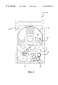
- FIG. 4 illustrates a hard disk drive which utilizes the method of the present invention.
- FIG. 5 is a block diagram of portions of an integrated circuit read channel in accordance with the present invention.
- FIG. 6 illustrates the layout of a typical sector of the disk 102 .
- FIG. 7A illustrates the layout of a sector of a plurality of calibration tracks showing the E burst which comprises servo bits E 0 -E 40 , provided in accordance with the principles of the present invention.
- FIG. 7B illustrates one embodiment of the E burst profile as provided by reading the servo bits E 0 -E 40 of FIG. 7A, in accordance with the principles of the present invention.
- FIG. 8 illustrates a plurality of servo burst signals (A, B, C, D), a plurality of position signals (N. P, N ⁇ , P ⁇ ) and a plurality of servo position signals (Y, X, W and Z) that are generated based on the E burst profile of FIG. 7 B.
- FIG. 9 illustrates a plurality of composite position signals (Y p , X p , W p and Z p ) that is generated based on the plurality of servo position signals (Y, X, W and Z).
- FIG. 10 illustrates a linear position signal that is generated based on the composite servo position signals.
- the present invention utilizes information obtained from a plurality of servo bits E 0 -E 40 to provide linear position information for aligning the head 110 instead of using only two servo signals, (A ⁇ B) or (C ⁇ D), as used in conventional techniques.
- the servo bits E 0 -E 40 are used in conjunction with a linearization technique to provide linear position information.
- FIG. 3A illustrates a servo writing system 10 which implements the servo writing process of the present invention.
- the servo writing system 10 directs the servo writing process by positioning the read/write heads in a magnetic disk drive from a master arm and motor.
- the servo writing system 10 includes a master drive assembly 12 which includes a master arm 14 that has a master voice coil motor 16 .
- the servo writing system 10 also comprises a hard drive assembly 18 which includes a hard drive arm 20 that has a hard drive voice coil motor 22 .
- a laser interferometer 24 is used to measure the position of the master arm 14 . This information is relayed to a master arm servo controller 26 , which moves the master arm 14 to the desired track of the data storage disk in which data is to be recorded.
- the laser interferometer 24 detects the position of the master arm 14 by monitoring light reflected off a reflector 26 mounted on the master arm 14 . This information is relayed to the master arm servo controller 26 , which also receives a position command signal from an external source, such as a computer, which is programmed to coordinate servo writing.
- a mechanical link between the master arm 14 and the hard drive arm 18 is established with the use of a mechanical push-pin 30 , as shown in FIGS. 3A and 3B.
- the mechanical push-pin 30 is attached at one end to the master arm 14 and extends into the hard drive through an access slot.
- the hard drive arm 20 is biased by its motor to press against the side of the push pin and follow the master arm 14 .
- This mechanical positioning system enables the hard drive arm 20 to track movement of the master arm 14 , and thus assure writing of servo information at the proper radius of the hard drive assembly 18 .
- the servo writing system 10 directs the servo writing process by positioning the read/write heads in a magnetic disk drive from a master arm and motor.
- a position command signal from an external source, such as a computer, directs the master arm 14 to position the read/write heads in the hard drive arm 20 to write a plurality of servo bursts in the data field of a calibration track on one or more disks of the hard drive assembly 18 .
- the plurality of servo bursts will later be used in providing position signal information for the hard disk drive 18 in accordance with the principles of the present invention.
- the assembly 108 also contains a voice coil motor 118 which moves the heads 110 a-d collectively relative to the disks 102 .
- the spin motor 104 , voice coil 118 and the heads 110 are coupled to a number of electronic circuits 120 mounted to a printed circuit board 122 .
- the electronic circuits 120 typically include a read channel circuit, a microprocessor-based controller and a random access memory (RAM) device.
- FIG. 5 is a block diagram of an electronic circuit 120 of the drive.
- the electronic circuit 120 includes a preamplifier 122 which is coupled to a read/write (R/W) channel circuit 124 .
- the R/W channel circuit 124 includes a RIW Automatic Gain Control (AGC), a filter circuit 126 , a fullwave rectifier 128 and a peak detector 130 .
- the electronic circuit 120 further comprises a microprocessor-based servo controller 132 which includes an analog-to-digital converter (ADC) 134 , a digital signal processor (DSP) 136 , a burst sequencer and timing circuit 138 and a memory 140 , such as a random access memory (RAM) device.
- ADC analog-to-digital converter
- DSP digital signal processor
- a burst sequencer and timing circuit 138 such as a random access memory (RAM) device.
- RAM random access memory
- the electronic circuit 120 is coupled to one of the magnetic heads 110 which senses the magnetic field of a magnetic disk 102 .
- the head 110 When reading the servo information located in the servo field region 10 on the disk 102 , the head 110 generates a read signal that corresponds to the magnetic field of the disk 102 .
- the read signal is first amplified by the preamplifier 122 , and then provided to the R/W channel circuit 124 .
- the AGC data included in the read signal is provided to the R/W AGC and filter circuit 126 .
- the R/W AGC circuit in circuit 126 monitors the AGC data provided by the read signal and the read signal is then filtered by the filter circuit located in the R/W AGC and filter circuit 126 .
- the fullwave rectifier 128 rectifies the read signal and provides the rectified read signal to the peak detector 130 .
- the peak detector 130 detects the amplitude of the read signal.
- the read signal is then provided to the ADC 134 which provides digitized samples of the analog read signal.
- the digitized signal is then provided to a digital signal processor (DSP) 136 which first reconstructs a portion of the E burst profile. Upon reading all 41 E servo bits E 0 -E 40 , the entire E burst profile may be reconstructed. Based on the reconstructed E burst profile, the DSP 136 reconstructs the four servo bursts A, B, C and D.
- the DSP determines the non-linear characteristics of the track profile and implements a linearization technique to generate a position offset signal Q which is stored in memory 140 and subsequently provided to the actuator arm assembly 108 to move the heads 110 .
- FIG. 6 illustrates the layout of a typical sector in accordance with the principles of the present invention.
- data is stored within sectors of radially concentric tracks located across the disk 102 .
- a typical sector will have an automatic gain control (AGC) field 150 , a synchronization (sync) field 152 , a gray code field 154 that identifies the track, an identification (ID) field 156 that defines the sector, a servo field 158 which includes a number of servo bits A, B, C, D, a data field 160 which contains the data and an error correction code field 162 .
- AGC automatic gain control
- sync synchronization
- gray code field 154 that identifies the track
- ID identification
- servo field 158 which includes a number of servo bits A, B, C, D
- a data field 160 which contains the data and an error correction code field 162 .
- the present invention provides a plurality of servo bits E 0 -E 40 , which are written in each data field 160 of a calibration track of the disk 102 , as shown in FIG. 7 A.
- the servo bits E 0 -E 40 may be written across a set of two calibration tracks.
- a set of the servo bits E 0 -E 40 may be written across three sets of calibration tracks. Such an arrangement facilitates greater accuracy in providing servo information.
- the servo bits E 0 -E 40 are written on the disk 102 by read/write head 110 under the control of the master arm 14 (FIG. 3 A). Each of the servo bits E 0 -E 40 will be referred to as an E bit.
- the master arm 14 first positions the hard drive arm 20 to a calibration track T ⁇ 1 that is adjacent to a primary calibration track T 0 .
- a first calibration burst E 0 is written in the data field 160 of the calibration track T ⁇ 1 at the center of the track T ⁇ 1 .
- the calibration burst E 0 is identical in amplitude and phase to the D servo burst.
- the master arm 14 then moves the hard drive arm 20 to a second position that is offset radially from E 0 (in the direction towards T 0 ) by 5% of the width of the calibration track T 0 .
- the read/write head 110 is then directed to write the servo burst E 1 at this second position.
- E 1 is written at a 1 microsecond delay from E 0 .
- This process is repeated for E 2 through E 40 , for a total of 41 E bursts.
- the servo bits E 0 -E 40 will span over a region covering three calibration tracks, T ⁇ 1 , T 0 and T +1 .
- the process of writing the E servo bits is repeated for all data fields 160 on the calibration tracks T ⁇ 1 , T 0 and T +1 .
- the process for writing the E servo bits may be applied to all read/write heads 110 a-d on all sides of the disks 102 of the disk pack 100 . Burst trimming, as is known in the art, may also be applied to the E servo bits.
- two sets of the servo bits E 0 -E 40 will be written over two sets of three calibration tracks as shown in FIG. 7 A.
- a greater number of sets of servo bits E 0 -E 40 may be utilized over a greater number of calibration tracks.
- fewer or a greater number of E servo bits may be utilized in generating a position offset signal.
- the head 110 is first moved to the calibration track(s), which may be in the outer or inner diameter of the disk 102 .
- the head 110 is first directed to read the A and B (or the C and D) servo bursts so as to align itself with the center of the calibration track.
- the head 110 is next directed to read the servo information provided by each of the E bursts, i.e., E 0 -E 40 , while remaining over the centerline of the calibration track.
- the servo information read is provided to the DSP 136 , which reconstructs the E burst profile as shown in FIG. 7B, based on the servo bits E 0 -E 40 that were read.
- the electronic circuits 120 then utilize the E burst profile to reconstruct all four servo bursts A, B, C and D by adjusting the phase offset of each burst A, B, C or D with respect to the E burst profile.
- FIG. 8 illustrates the reconstructed servo bursts A, B, C and D.
- the information obtained from all four servo bursts A, B, C and D is then utilized, together with a linearization technique, to provide improved linear position information for aligning the head 110 .
- This linearization process is provided as follows.
- N ( A ⁇ B ) ⁇ ( C ⁇ D );
- N ⁇ ⁇ ( A ⁇ B )+( C ⁇ D );
- a set of four position signals namely, W, X, Y and Z are generated, where W, X, Y and Z are the linear portions of the functions N.
- P, N ⁇ and P ⁇ respectively, where the slopes of the functions are positive.
- the data points which make up the W, X, Y and Z position signals may be calculated from the various E servo bits.
- a set of four composite position signals W p , X p , Y p and Z p based on the position signals W, X, Y and Z are then generated.
- the position signal W p results from duplicating the signal W and then shifting and aligning the original signal W and the duplicated signal W duplicate to provide the signal W p as shown in FIG. 9 .
- the other signals X p , Y p and Z p are similarly obtained.
- a reference slope for the function representing each position signal is obtained. This is accomplished by obtaining the line segment represented by the two end data points of each function.
- the slope of each line segment corresponding to W, X, Y and Z is referred to as m w , m x , m y , and m z respectively.
- Each function is then linearized using its corresponding slope value. For example,
- W m w ( E 0 , E 1 , . . . , E 40 );
- X m x ( E 0 , E 1 , . . . , E 40 );
- Y m y ( E 0 , E 1 , . . . , E 40 );
- the slope a and constant b of each linear segment between two consecutive data points for each of the W, X, Y and Z position signals are then calculated and stored in memory. For example, in the following table, the slope a y0 and constant b y0 for the line segment formed by data points Y 0 & Y 1 , are obtained.
- the data points for an ideal, linear position signal function Y L are calculated. This is accomplished by calculating an offset signal Y p ′, which when added to Y will provide the ideal position signal Y L as shown in FIG. 10 . For example, if Y L is constructed from the data points Y 1 , . . . Y 10 , then
- Y L f ( Y 1 ,Y 2 , . . . Y 10 )
- Y 1 f ( Y 1 , m y1 , a y1 , b y1 )
- Y 10 f ( Y 10 , m y2 , a y2 , b y2 )
- the linear position signal functions X L , W L and Z L may be similarly obtained.
- an ideal position signal may be provided based on the E servo bits, E 0 to E 40 .
- servo information which varies linearly with respect to the track position of an MR head is provided.
- the provision of such servo information facilitates linearization of the servo loop gain, which improves the read throughput performance and consequently, increased product yields.
Abstract
Description
| PO- | |||
| SITION | |||
| SLOPE | CONSTANT | DATA POINTS | SIGNAL |
| ay0, | by0, | Y0 & Y1, . . ., Y9 & Y10 | Yp |
| ay1, . . .ay9 | by1, . . .by9 | ||
| ax0, | bx0, | X0 & X1, . . ., X9 & X10 | Xp |
| ax1, . . .ax9 | bx1, . . .bx9 | ||
| aw0, | bw0, | W0 & W1, . . ., W9 & W10 | Wp |
| aw1, . . .aw9 | bw1, . . .bw9 | ||
| az0, | bz0, | Z0 & Z1, . . ., Z9 & Z10 | Zp |
| azy1, . . .az9 | bzy1, . . .bz9 | ||
Claims (17)
Priority Applications (4)
| Application Number | Priority Date | Filing Date | Title |
|---|---|---|---|
| US09/134,277 US6429994B1 (en) | 1998-08-14 | 1998-08-14 | Method and apparatus for providing servo gain linearization for a magneto-resistive head |
| DE19938468A DE19938468B4 (en) | 1998-08-14 | 1999-08-13 | Method and apparatus for providing servo gain linearization for a magnetoresistive head |
| KR10-1999-0033536A KR100376807B1 (en) | 1998-08-14 | 1999-08-14 | Method and apparatus for providing servo gain linearization for a magneto-resistive head |
| GB9919262A GB2341266A (en) | 1998-08-14 | 1999-08-16 | Servo gain linearization |
Applications Claiming Priority (1)
| Application Number | Priority Date | Filing Date | Title |
|---|---|---|---|
| US09/134,277 US6429994B1 (en) | 1998-08-14 | 1998-08-14 | Method and apparatus for providing servo gain linearization for a magneto-resistive head |
Publications (1)
| Publication Number | Publication Date |
|---|---|
| US6429994B1 true US6429994B1 (en) | 2002-08-06 |
Family
ID=22462609
Family Applications (1)
| Application Number | Title | Priority Date | Filing Date |
|---|---|---|---|
| US09/134,277 Expired - Fee Related US6429994B1 (en) | 1998-08-14 | 1998-08-14 | Method and apparatus for providing servo gain linearization for a magneto-resistive head |
Country Status (4)
| Country | Link |
|---|---|
| US (1) | US6429994B1 (en) |
| KR (1) | KR100376807B1 (en) |
| DE (1) | DE19938468B4 (en) |
| GB (1) | GB2341266A (en) |
Cited By (7)
| Publication number | Priority date | Publication date | Assignee | Title |
|---|---|---|---|---|
| US20030189781A1 (en) * | 2002-04-09 | 2003-10-09 | International Business Machines Corporation | Method, system, and article of manufacture for self-servowriting a disk |
| EP1494213A2 (en) * | 2003-06-30 | 2005-01-05 | Fujitsu Limited | Head position demodulating method and disk apparatus |
| US6876506B1 (en) * | 1999-05-11 | 2005-04-05 | Hitachi Maxell, Ltd. | Information recording medium, information recording/reproducing head, and information storage device |
| EP1569206A1 (en) * | 2004-01-30 | 2005-08-31 | Samsung Electronics Co., Ltd. | Method of testing servo burst signal of hard disk drive and recording medium and apparatus adapted therefor |
| US7372650B1 (en) * | 2004-06-21 | 2008-05-13 | Western Digital Technologies, Inc. | Rotating media storage device having a calibration track with unique calibration servo synch marks |
| US11557319B1 (en) | 2021-08-24 | 2023-01-17 | Seagate Technology Llc | Read offset calibration for error recovery |
| US11568895B1 (en) * | 2021-09-03 | 2023-01-31 | Seagate Technology Llc | Read offset calibration for error recovery |
Citations (67)
| Publication number | Priority date | Publication date | Assignee | Title |
|---|---|---|---|---|
| US4371902A (en) | 1980-06-30 | 1983-02-01 | International Business Machines Corporation | Disk initialization method |
| US4539662A (en) | 1981-06-04 | 1985-09-03 | Pioneer Electronic Corporation | Method and system for optically recording and playing back information on a recording medium having magnetization film thereon |
| US4802033A (en) | 1986-11-07 | 1989-01-31 | Eastman Kodak Company | Predictive positioning offset compensation for high TPI disk systems |
| US4811135A (en) * | 1985-11-20 | 1989-03-07 | Magnetic Peripherals Inc. | Tri-phase servo pattern for providing information for positioning the transducers of a magnetic disk storage drive |
| US4823212A (en) | 1986-11-26 | 1989-04-18 | Hewlett-Packard Company | Sampled servo code format and system for a disc drive |
| US4890172A (en) | 1988-09-27 | 1989-12-26 | Digital Equipment Corporation | Automatic servo gain calibration system for a disk drive |
| US4937689A (en) | 1986-10-14 | 1990-06-26 | Maxtor Corporation | Apparatus for controlling seek strategy of read/write head in a disk drive |
| US4977472A (en) * | 1988-03-28 | 1990-12-11 | Seagate Technology, Inc. | Servo address system |
| US4982295A (en) | 1988-01-28 | 1991-01-01 | Mitsumi Electric Co., Ltd. | Method for centering a read/write head of a magnetic data storage apparatus on a track of a magnetic disk |
| US5036408A (en) | 1988-05-12 | 1991-07-30 | Digital Equipment Corporation | High efficiency disk format and synchronization system |
| US5050146A (en) | 1989-07-31 | 1991-09-17 | Literal Corporation | Track seek recovery system and method |
| US5053899A (en) | 1987-07-15 | 1991-10-01 | Nec Corporation | Exact position control of a relative position between a magnetic head and a recording medium |
| US5182684A (en) | 1989-03-08 | 1993-01-26 | International Business Machines Corporation | Estimator positioning system and method |
| US5210662A (en) | 1990-03-09 | 1993-05-11 | Matsushita Electric Industrial Co., Ltd. | Tracking control apparatus for magnetic disk |
| US5235478A (en) | 1989-12-15 | 1993-08-10 | Sony Corporation | Disc drive apparatus with servo tracks offset from data tracks |
| US5255136A (en) | 1990-08-17 | 1993-10-19 | Quantum Corporation | High capacity submicro-winchester fixed disk drive |
| US5291110A (en) | 1991-10-31 | 1994-03-01 | Integral Peripherals, Inc. | Low acoustic noise seeking method and apparatus |
| EP0601855A2 (en) | 1992-12-09 | 1994-06-15 | Japan Radio Co., Ltd | Adaptive equalizer capable of compensating for carrier frequency offset |
| US5333140A (en) | 1991-10-03 | 1994-07-26 | Helios Incorporated | Servowriter/certifier |
| US5408367A (en) | 1993-09-20 | 1995-04-18 | Integral Peripherals, Inc. | Method of optimizing operation of disk drive |
| GB2285165A (en) | 1993-12-17 | 1995-06-28 | Ibm | A disk sector format which eliminates the need for sector identifiers |
| EP0663766A1 (en) | 1994-01-18 | 1995-07-19 | Daewoo Electronics Co., Ltd | Equalization apparatus with a fast updating operation of the filter coefficients |
| US5448429A (en) | 1992-11-10 | 1995-09-05 | Cribbs; Daniel F. | Self-servowriting disk drive and method |
| WO1995024035A1 (en) | 1994-03-03 | 1995-09-08 | Cirrus Logic, Inc. | A table driven method and apparatus for automatic split field processing |
| US5450249A (en) | 1993-05-19 | 1995-09-12 | American Telephone And Telegraph Company | Demodulator circuit |
| US5452285A (en) * | 1993-09-30 | 1995-09-19 | Polaroid Corporation | Uniformly distributed servo data for optical information storage medium |
| US5453887A (en) | 1987-01-13 | 1995-09-26 | Canon Denshi Kabushiki Kaisha | Head tracking servo pattern |
| US5465035A (en) | 1993-05-11 | 1995-11-07 | Quantum Corporation | Band limited control of a flexible structure using piecewise trigonometric input signals |
| US5500776A (en) | 1993-12-16 | 1996-03-19 | Seagate Technology, Inc. | Self-calibration for computer disk read/write offsets |
| US5523902A (en) | 1993-10-25 | 1996-06-04 | Syquest Technology, Inc. | Servo burst pattern for removing offset caused by magnetic distortion and method associated therewith |
| EP0717559A2 (en) | 1994-12-14 | 1996-06-19 | Daewoo Electronics Co., Ltd | Equalization apparatus with effective coefficient updating operation |
| EP0718827A2 (en) | 1994-12-22 | 1996-06-26 | International Business Machines Corporation | System and method for target track determination in a data storage disk drive |
| WO1996023305A1 (en) | 1995-01-27 | 1996-08-01 | Seagate Technology, Inc. | Dual identification for data fields of a disk drive |
| US5570247A (en) | 1992-06-11 | 1996-10-29 | International Business Machines Corporation | Self servo writing file |
| US5581420A (en) | 1993-03-08 | 1996-12-03 | International Business Machines Corporation | Method and system for determining a radial positioning valve used for writing tracks at a desired track pitch |
| US5587850A (en) * | 1994-08-26 | 1996-12-24 | Quantum Corporation | Data track pattern including embedded servo sectors for magneto-resistive read/inductive write head structure for a disk drive |
| US5600506A (en) | 1995-05-10 | 1997-02-04 | Conner Peripherals, Inc. | Apparatus and method for determining the position of a transducer relative to a disk surface in a disk drive system |
| US5606469A (en) | 1992-03-30 | 1997-02-25 | Fujitsu Limited | Method for correcting offset in a magnetic disk including apparent offtrack cancellation |
| US5608587A (en) | 1993-08-06 | 1997-03-04 | Seagate Technology, Inc. | Method using magnetic disk servo pattern with buried identification patterns |
| GB2307089A (en) | 1995-11-08 | 1997-05-14 | Samsung Electronics Co Ltd | Hard disk drive with reduced servo field |
| US5631783A (en) | 1994-12-21 | 1997-05-20 | Samsung Electronics Co., Ltd. | Magnetic disc apparatus employing constant-density recording and driver access method where a wedge ID field and a pseudo ID field are recorded |
| US5640423A (en) | 1993-12-16 | 1997-06-17 | Signal Science, Inc. | Method for signal transmission using spectrally efficient orthogonal modulation |
| GB2308488A (en) | 1995-12-19 | 1997-06-25 | Samsung Electronics Co Ltd | Hard disk drive having extended data region |
| US5657179A (en) | 1991-03-28 | 1997-08-12 | Seagate Technology, Inc. | Method for reducing noise during track seeking in a disc drive |
| US5659436A (en) | 1994-12-02 | 1997-08-19 | International Business Machines Corporation | Radial self propagation pattern generation for disk file servowriting |
| US5666238A (en) | 1993-12-28 | 1997-09-09 | Kabushiki Kaisha Toshiba | Data sector control apparatus and method for disk storage system |
| US5680451A (en) | 1995-11-14 | 1997-10-21 | Paradyne Corporation | Listener echo cancellation for modems |
| US5680270A (en) | 1995-03-24 | 1997-10-21 | Nec Corporation | Floppy disk apparatus which adjusts gain conforming to operation of carriage |
| US5691857A (en) | 1995-09-29 | 1997-11-25 | Quantum Corporation | Method using matched filters for determining head positioner micro-jog in hard disk drive employing magneto-resistive heads |
| US5696647A (en) | 1994-03-28 | 1997-12-09 | Seagate Technology, Inc. | Method for carrying out seeks in a hard disc drive to limit the generation of acoustic noise including using a slew rate limit |
| US5710677A (en) | 1995-12-18 | 1998-01-20 | Seagate Technology, Inc. | Method of detecting and isolating defective servo bursts |
| US5715105A (en) | 1992-09-28 | 1998-02-03 | Hitachi, Ltd. | Method of and apparatus for recording on and reproducing from disk-type recording medium having recording tracks with sectors each having an ID area and a data area |
| US5734680A (en) | 1995-08-09 | 1998-03-31 | Hewlett-Packard Co. | Analog implementation of a partial response maximum likelihood (PRML) read channel |
| US5748677A (en) | 1996-01-16 | 1998-05-05 | Kumar; Derek D. | Reference signal communication method and system |
| US5771130A (en) | 1996-04-15 | 1998-06-23 | Phase Metrics | Method and apparatus for non-contact servo writing |
| US5771131A (en) | 1996-07-18 | 1998-06-23 | Quantum Corporation | Tracking in hard disk drive using magnetoresistive heads |
| US5798883A (en) | 1995-05-12 | 1998-08-25 | Samsung Electronics Co., Ltd. | Method for servo defect management of a magnetic disk in hard disk drive |
| US5867353A (en) * | 1994-09-30 | 1999-02-02 | Maxtor Corporation | Off-track PES calibration for a magneto-resistive element |
| US5867343A (en) * | 1996-05-01 | 1999-02-02 | Samsung Electronics, Ltd. | Method and apparatus for storing position offset information on a hard drive assembly cylinder |
| US5867337A (en) | 1995-03-17 | 1999-02-02 | Kabushiki Saisha Toshiba | Disk drive of a sector servo system for positioning and controlling a head at a target position on a disk |
| US5892634A (en) | 1995-05-23 | 1999-04-06 | Kabushiki Kaisha Toshiba | Method and apparatus for heat positioning control in disk storage system |
| US5901009A (en) | 1995-05-31 | 1999-05-04 | International Business Machines Corporation | Reduced seek acoustic noise direct access storage device |
| US5917670A (en) | 1996-10-15 | 1999-06-29 | Quantum Corporation | Method for recovering data from disk with magneto-resistive head in presence of thermal asperities |
| US5946157A (en) | 1997-07-21 | 1999-08-31 | Western Digital Corporation | Method of seamlessly recording circumferentially successive servo bursts that overlap one another |
| US6031684A (en) | 1997-06-03 | 2000-02-29 | Seagate Technology, Inc. | Servo gain optimization using model reference seeks in a disc drive |
| US6118616A (en) | 1993-11-27 | 2000-09-12 | Samsung Electronics Co., Ltd. | Digital servo control method for controlling a head driver for moving a head to a target track |
| US6178060B1 (en) | 1998-07-13 | 2001-01-23 | Seagate Technology Llc | Current profile shaping to reduce disc drive seek time variation and acoustic noise generation |
Family Cites Families (10)
| Publication number | Priority date | Publication date | Assignee | Title |
|---|---|---|---|---|
| US4157577A (en) * | 1977-11-14 | 1979-06-05 | International Business Machines Corporation | Rotatable storage apparatus with digitally responsive circuitry for track selection |
| JPS5622265A (en) * | 1979-07-30 | 1981-03-02 | Fujitsu Ltd | Servo pattern for magnetic head alignment |
| JPH05189903A (en) * | 1992-01-14 | 1993-07-30 | Nec Corp | Head positioning servo device and method therefor |
| JPH09139035A (en) * | 1995-11-13 | 1997-05-27 | Toshiba Corp | Disk recording and reproducing system and its head positioning control method |
| JPH09312074A (en) * | 1996-05-23 | 1997-12-02 | Toshiba Corp | Recording medium for data recording/reproducing device and data recording/reproducing device provided therewith |
| JP2927234B2 (en) * | 1996-04-26 | 1999-07-28 | 日本電気株式会社 | Servo pattern writing method for magnetic disk drive |
| US5781361A (en) * | 1996-05-01 | 1998-07-14 | Samsung Electronics, Ltd. | Method and apparatus for generating servo information |
| US6046879A (en) * | 1996-05-16 | 2000-04-04 | Seagate Technology, Inc. | Weighted linearization of a position error signal in a disc drive |
| US5757574A (en) * | 1996-05-29 | 1998-05-26 | International Business Machines Corporation | Methods and systems for self-servowriting including maintaining a reference level within a usable dynamic range |
| KR100258340B1 (en) * | 1996-09-05 | 2000-06-01 | 윤종용 | Self calibration drive using servo burst for servo calibration |
-
1998
- 1998-08-14 US US09/134,277 patent/US6429994B1/en not_active Expired - Fee Related
-
1999
- 1999-08-13 DE DE19938468A patent/DE19938468B4/en not_active Expired - Fee Related
- 1999-08-14 KR KR10-1999-0033536A patent/KR100376807B1/en not_active IP Right Cessation
- 1999-08-16 GB GB9919262A patent/GB2341266A/en not_active Withdrawn
Patent Citations (73)
| Publication number | Priority date | Publication date | Assignee | Title |
|---|---|---|---|---|
| US4371902A (en) | 1980-06-30 | 1983-02-01 | International Business Machines Corporation | Disk initialization method |
| US4539662A (en) | 1981-06-04 | 1985-09-03 | Pioneer Electronic Corporation | Method and system for optically recording and playing back information on a recording medium having magnetization film thereon |
| US4811135A (en) * | 1985-11-20 | 1989-03-07 | Magnetic Peripherals Inc. | Tri-phase servo pattern for providing information for positioning the transducers of a magnetic disk storage drive |
| US4937689A (en) | 1986-10-14 | 1990-06-26 | Maxtor Corporation | Apparatus for controlling seek strategy of read/write head in a disk drive |
| US4802033A (en) | 1986-11-07 | 1989-01-31 | Eastman Kodak Company | Predictive positioning offset compensation for high TPI disk systems |
| US4823212A (en) | 1986-11-26 | 1989-04-18 | Hewlett-Packard Company | Sampled servo code format and system for a disc drive |
| US5453887A (en) | 1987-01-13 | 1995-09-26 | Canon Denshi Kabushiki Kaisha | Head tracking servo pattern |
| US5053899A (en) | 1987-07-15 | 1991-10-01 | Nec Corporation | Exact position control of a relative position between a magnetic head and a recording medium |
| US4982295A (en) | 1988-01-28 | 1991-01-01 | Mitsumi Electric Co., Ltd. | Method for centering a read/write head of a magnetic data storage apparatus on a track of a magnetic disk |
| US4977472A (en) * | 1988-03-28 | 1990-12-11 | Seagate Technology, Inc. | Servo address system |
| US5036408A (en) | 1988-05-12 | 1991-07-30 | Digital Equipment Corporation | High efficiency disk format and synchronization system |
| US4890172A (en) | 1988-09-27 | 1989-12-26 | Digital Equipment Corporation | Automatic servo gain calibration system for a disk drive |
| US5182684A (en) | 1989-03-08 | 1993-01-26 | International Business Machines Corporation | Estimator positioning system and method |
| US5050146A (en) | 1989-07-31 | 1991-09-17 | Literal Corporation | Track seek recovery system and method |
| US5235478A (en) | 1989-12-15 | 1993-08-10 | Sony Corporation | Disc drive apparatus with servo tracks offset from data tracks |
| US5210662A (en) | 1990-03-09 | 1993-05-11 | Matsushita Electric Industrial Co., Ltd. | Tracking control apparatus for magnetic disk |
| US5255136A (en) | 1990-08-17 | 1993-10-19 | Quantum Corporation | High capacity submicro-winchester fixed disk drive |
| US5657179A (en) | 1991-03-28 | 1997-08-12 | Seagate Technology, Inc. | Method for reducing noise during track seeking in a disc drive |
| US5333140A (en) | 1991-10-03 | 1994-07-26 | Helios Incorporated | Servowriter/certifier |
| US5291110A (en) | 1991-10-31 | 1994-03-01 | Integral Peripherals, Inc. | Low acoustic noise seeking method and apparatus |
| US5465034A (en) | 1991-10-31 | 1995-11-07 | Integral Peripherals, Inc. | Low acoustic noise seeking method and apparatus |
| US5606469A (en) | 1992-03-30 | 1997-02-25 | Fujitsu Limited | Method for correcting offset in a magnetic disk including apparent offtrack cancellation |
| US5570247A (en) | 1992-06-11 | 1996-10-29 | International Business Machines Corporation | Self servo writing file |
| US5715105A (en) | 1992-09-28 | 1998-02-03 | Hitachi, Ltd. | Method of and apparatus for recording on and reproducing from disk-type recording medium having recording tracks with sectors each having an ID area and a data area |
| US5448429A (en) | 1992-11-10 | 1995-09-05 | Cribbs; Daniel F. | Self-servowriting disk drive and method |
| EP0601855A2 (en) | 1992-12-09 | 1994-06-15 | Japan Radio Co., Ltd | Adaptive equalizer capable of compensating for carrier frequency offset |
| US5581420A (en) | 1993-03-08 | 1996-12-03 | International Business Machines Corporation | Method and system for determining a radial positioning valve used for writing tracks at a desired track pitch |
| US5615058A (en) | 1993-03-08 | 1997-03-25 | International Business Machines Corporation | Method and system for writing a servo-pattern on a storage medium |
| US5465035A (en) | 1993-05-11 | 1995-11-07 | Quantum Corporation | Band limited control of a flexible structure using piecewise trigonometric input signals |
| US5450249A (en) | 1993-05-19 | 1995-09-12 | American Telephone And Telegraph Company | Demodulator circuit |
| US5608587A (en) | 1993-08-06 | 1997-03-04 | Seagate Technology, Inc. | Method using magnetic disk servo pattern with buried identification patterns |
| US5408367A (en) | 1993-09-20 | 1995-04-18 | Integral Peripherals, Inc. | Method of optimizing operation of disk drive |
| US5452285A (en) * | 1993-09-30 | 1995-09-19 | Polaroid Corporation | Uniformly distributed servo data for optical information storage medium |
| US5523902A (en) | 1993-10-25 | 1996-06-04 | Syquest Technology, Inc. | Servo burst pattern for removing offset caused by magnetic distortion and method associated therewith |
| US6118616A (en) | 1993-11-27 | 2000-09-12 | Samsung Electronics Co., Ltd. | Digital servo control method for controlling a head driver for moving a head to a target track |
| US5500776A (en) | 1993-12-16 | 1996-03-19 | Seagate Technology, Inc. | Self-calibration for computer disk read/write offsets |
| US5640423A (en) | 1993-12-16 | 1997-06-17 | Signal Science, Inc. | Method for signal transmission using spectrally efficient orthogonal modulation |
| GB2285165A (en) | 1993-12-17 | 1995-06-28 | Ibm | A disk sector format which eliminates the need for sector identifiers |
| US5666238A (en) | 1993-12-28 | 1997-09-09 | Kabushiki Kaisha Toshiba | Data sector control apparatus and method for disk storage system |
| EP0663766A1 (en) | 1994-01-18 | 1995-07-19 | Daewoo Electronics Co., Ltd | Equalization apparatus with a fast updating operation of the filter coefficients |
| WO1995024035A1 (en) | 1994-03-03 | 1995-09-08 | Cirrus Logic, Inc. | A table driven method and apparatus for automatic split field processing |
| US5751513A (en) | 1994-03-28 | 1998-05-12 | Seagate Technology, Inc. | Method for carrying out seeks in a hard disc drive to limit the generation of acoustic noise |
| US5760992A (en) | 1994-03-28 | 1998-06-02 | Seagate Technology, Inc. | Method for carrying out seeks in a hard disc drive to limit the generation of acoustic noise |
| US5696647A (en) | 1994-03-28 | 1997-12-09 | Seagate Technology, Inc. | Method for carrying out seeks in a hard disc drive to limit the generation of acoustic noise including using a slew rate limit |
| US5587850A (en) * | 1994-08-26 | 1996-12-24 | Quantum Corporation | Data track pattern including embedded servo sectors for magneto-resistive read/inductive write head structure for a disk drive |
| US5796543A (en) | 1994-08-26 | 1998-08-18 | Quantum Corporation | Data track pattern including embedded servo sectors for magneto-resistive read/inductive write head structure for a disk drive |
| US5867353A (en) * | 1994-09-30 | 1999-02-02 | Maxtor Corporation | Off-track PES calibration for a magneto-resistive element |
| US5659436A (en) | 1994-12-02 | 1997-08-19 | International Business Machines Corporation | Radial self propagation pattern generation for disk file servowriting |
| EP0717559A2 (en) | 1994-12-14 | 1996-06-19 | Daewoo Electronics Co., Ltd | Equalization apparatus with effective coefficient updating operation |
| US5631783A (en) | 1994-12-21 | 1997-05-20 | Samsung Electronics Co., Ltd. | Magnetic disc apparatus employing constant-density recording and driver access method where a wedge ID field and a pseudo ID field are recorded |
| EP0718827A2 (en) | 1994-12-22 | 1996-06-26 | International Business Machines Corporation | System and method for target track determination in a data storage disk drive |
| WO1996023305A1 (en) | 1995-01-27 | 1996-08-01 | Seagate Technology, Inc. | Dual identification for data fields of a disk drive |
| US5867337A (en) | 1995-03-17 | 1999-02-02 | Kabushiki Saisha Toshiba | Disk drive of a sector servo system for positioning and controlling a head at a target position on a disk |
| US5680270A (en) | 1995-03-24 | 1997-10-21 | Nec Corporation | Floppy disk apparatus which adjusts gain conforming to operation of carriage |
| US5600506A (en) | 1995-05-10 | 1997-02-04 | Conner Peripherals, Inc. | Apparatus and method for determining the position of a transducer relative to a disk surface in a disk drive system |
| US5798883A (en) | 1995-05-12 | 1998-08-25 | Samsung Electronics Co., Ltd. | Method for servo defect management of a magnetic disk in hard disk drive |
| US5892634A (en) | 1995-05-23 | 1999-04-06 | Kabushiki Kaisha Toshiba | Method and apparatus for heat positioning control in disk storage system |
| US5901009A (en) | 1995-05-31 | 1999-05-04 | International Business Machines Corporation | Reduced seek acoustic noise direct access storage device |
| US5734680A (en) | 1995-08-09 | 1998-03-31 | Hewlett-Packard Co. | Analog implementation of a partial response maximum likelihood (PRML) read channel |
| US5691857A (en) | 1995-09-29 | 1997-11-25 | Quantum Corporation | Method using matched filters for determining head positioner micro-jog in hard disk drive employing magneto-resistive heads |
| GB2307089A (en) | 1995-11-08 | 1997-05-14 | Samsung Electronics Co Ltd | Hard disk drive with reduced servo field |
| US5771126A (en) | 1995-11-08 | 1998-06-23 | Samsung Electronics Co., Ltd. | Hard disk drive with reduced sized servo sectors and driving method therefor |
| US5680451A (en) | 1995-11-14 | 1997-10-21 | Paradyne Corporation | Listener echo cancellation for modems |
| US5710677A (en) | 1995-12-18 | 1998-01-20 | Seagate Technology, Inc. | Method of detecting and isolating defective servo bursts |
| GB2308488A (en) | 1995-12-19 | 1997-06-25 | Samsung Electronics Co Ltd | Hard disk drive having extended data region |
| US5748677A (en) | 1996-01-16 | 1998-05-05 | Kumar; Derek D. | Reference signal communication method and system |
| US5771130A (en) | 1996-04-15 | 1998-06-23 | Phase Metrics | Method and apparatus for non-contact servo writing |
| US5867343A (en) * | 1996-05-01 | 1999-02-02 | Samsung Electronics, Ltd. | Method and apparatus for storing position offset information on a hard drive assembly cylinder |
| US5771131A (en) | 1996-07-18 | 1998-06-23 | Quantum Corporation | Tracking in hard disk drive using magnetoresistive heads |
| US5917670A (en) | 1996-10-15 | 1999-06-29 | Quantum Corporation | Method for recovering data from disk with magneto-resistive head in presence of thermal asperities |
| US6031684A (en) | 1997-06-03 | 2000-02-29 | Seagate Technology, Inc. | Servo gain optimization using model reference seeks in a disc drive |
| US5946157A (en) | 1997-07-21 | 1999-08-31 | Western Digital Corporation | Method of seamlessly recording circumferentially successive servo bursts that overlap one another |
| US6178060B1 (en) | 1998-07-13 | 2001-01-23 | Seagate Technology Llc | Current profile shaping to reduce disc drive seek time variation and acoustic noise generation |
Cited By (9)
| Publication number | Priority date | Publication date | Assignee | Title |
|---|---|---|---|---|
| US6876506B1 (en) * | 1999-05-11 | 2005-04-05 | Hitachi Maxell, Ltd. | Information recording medium, information recording/reproducing head, and information storage device |
| US20030189781A1 (en) * | 2002-04-09 | 2003-10-09 | International Business Machines Corporation | Method, system, and article of manufacture for self-servowriting a disk |
| US7126780B2 (en) * | 2002-04-09 | 2006-10-24 | Hitachi Global Storage Technologies Netherlands B.V. | Method, system, and article of manufacture for self-servowriting a disk |
| EP1494213A2 (en) * | 2003-06-30 | 2005-01-05 | Fujitsu Limited | Head position demodulating method and disk apparatus |
| EP1494213A3 (en) * | 2003-06-30 | 2006-03-29 | Fujitsu Limited | Head position demodulating method and disk apparatus |
| EP1569206A1 (en) * | 2004-01-30 | 2005-08-31 | Samsung Electronics Co., Ltd. | Method of testing servo burst signal of hard disk drive and recording medium and apparatus adapted therefor |
| US7372650B1 (en) * | 2004-06-21 | 2008-05-13 | Western Digital Technologies, Inc. | Rotating media storage device having a calibration track with unique calibration servo synch marks |
| US11557319B1 (en) | 2021-08-24 | 2023-01-17 | Seagate Technology Llc | Read offset calibration for error recovery |
| US11568895B1 (en) * | 2021-09-03 | 2023-01-31 | Seagate Technology Llc | Read offset calibration for error recovery |
Also Published As
| Publication number | Publication date |
|---|---|
| KR20000017310A (en) | 2000-03-25 |
| DE19938468A1 (en) | 2000-02-17 |
| GB9919262D0 (en) | 1999-10-20 |
| DE19938468B4 (en) | 2006-05-11 |
| KR100376807B1 (en) | 2003-03-19 |
| GB2341266A (en) | 2000-03-08 |
Similar Documents
| Publication | Publication Date | Title |
|---|---|---|
| US6519107B1 (en) | Hard disk drive having self-written servo burst patterns | |
| US6256160B1 (en) | Programmable, variable data track pitch | |
| US6995941B1 (en) | Method for improving head position determination in a disk drive | |
| US7304819B1 (en) | Method for writing repeatable runout correction values to a magnetic disk of a disk drive | |
| US5867353A (en) | Off-track PES calibration for a magneto-resistive element | |
| JP2554393B2 (en) | Position shift compensation method and device | |
| US5050017A (en) | Memory guided magnetic tape tracking | |
| US6760184B1 (en) | Compact servo pattern optimized for M-R heads | |
| US6982849B2 (en) | Method and apparatus for providing positional information on a disk | |
| EP1014343A1 (en) | Calibration method for use in head loading/unloading type disk apparatus | |
| US7095575B2 (en) | Magnetic disk apparatus, method for determining data track pitch, and self-servo write method | |
| US7106542B1 (en) | Method and apparatus for determining embedded runout correction values when self-servo writing or partial self-servo writing a disk drive | |
| US7006322B2 (en) | Method and apparatus for performing self-servo writing in a disk drive | |
| JP2004199863A (en) | Method for writing servo pattern | |
| USRE40955E1 (en) | Method and apparatus for storing position offset information on a hard drive assembly cylinder | |
| US6262859B1 (en) | Method and apparatus for providing servo information on a disk in a hard drive assembly | |
| US6429994B1 (en) | Method and apparatus for providing servo gain linearization for a magneto-resistive head | |
| US7054096B1 (en) | Method and apparatus for determining embedded runout correction values | |
| US6456451B1 (en) | Method and apparatus for disk drive seek control | |
| US6574068B1 (en) | Servo control using continuous position error signal with high order polynomial component | |
| US5781361A (en) | Method and apparatus for generating servo information | |
| US7355808B1 (en) | Method and apparatus for partial self-servo writing using servo wedge propagation | |
| US6043952A (en) | Method of positioning a head in a disk drive using groups of servo bursts | |
| KR0132059B1 (en) | Tracking servo control for disk drive | |
| KR100369281B1 (en) | Dual element head with radial offset optimized for minimal write-to-read track error |
Legal Events
| Date | Code | Title | Description |
|---|---|---|---|
| AS | Assignment |
Owner name: SAMSUNG ELECTRONICS CO., LTD., KOREA, REPUBLIC OF Free format text: ASSIGNMENT OF ASSIGNORS INTEREST;ASSIGNORS:VAN LE, ME;HUYNH, THOMAS;REEL/FRAME:009419/0469 Effective date: 19980812 |
|
| FPAY | Fee payment |
Year of fee payment: 4 |
|
| FEPP | Fee payment procedure |
Free format text: PAYOR NUMBER ASSIGNED (ORIGINAL EVENT CODE: ASPN); ENTITY STATUS OF PATENT OWNER: LARGE ENTITY |
|
| FPAY | Fee payment |
Year of fee payment: 8 |
|
| REMI | Maintenance fee reminder mailed | ||
| LAPS | Lapse for failure to pay maintenance fees | ||
| STCH | Information on status: patent discontinuation |
Free format text: PATENT EXPIRED DUE TO NONPAYMENT OF MAINTENANCE FEES UNDER 37 CFR 1.362 |
|
| FP | Lapsed due to failure to pay maintenance fee |
Effective date: 20140806 |