US6430231B1 - Generalized orthogonal designs for space-time codes for wireless communication - Google Patents
Generalized orthogonal designs for space-time codes for wireless communication Download PDFInfo
- Publication number
- US6430231B1 US6430231B1 US09/186,908 US18690898A US6430231B1 US 6430231 B1 US6430231 B1 US 6430231B1 US 18690898 A US18690898 A US 18690898A US 6430231 B1 US6430231 B1 US 6430231B1
- Authority
- US
- United States
- Prior art keywords
- symbols
- transmitter
- sets
- antennas
- matrix
- Prior art date
- Legal status (The legal status is an assumption and is not a legal conclusion. Google has not performed a legal analysis and makes no representation as to the accuracy of the status listed.)
- Expired - Lifetime
Links
- 238000013461 design Methods 0.000 title abstract description 38
- 238000004891 communication Methods 0.000 title description 6
- 239000011159 matrix material Substances 0.000 claims abstract description 35
- 229910052704 radon Inorganic materials 0.000 claims description 23
- 230000002123 temporal effect Effects 0.000 claims 6
- 238000000034 method Methods 0.000 abstract description 11
- 230000005540 biological transmission Effects 0.000 description 10
- 238000013459 approach Methods 0.000 description 7
- 238000007476 Maximum Likelihood Methods 0.000 description 5
- 238000010276 construction Methods 0.000 description 4
- 238000005562 fading Methods 0.000 description 4
- 238000012545 processing Methods 0.000 description 4
- 230000007704 transition Effects 0.000 description 4
- 230000000694 effects Effects 0.000 description 3
- 230000015556 catabolic process Effects 0.000 description 2
- 238000006731 degradation reaction Methods 0.000 description 2
- 238000010586 diagram Methods 0.000 description 2
- 238000005516 engineering process Methods 0.000 description 2
- SYUHGPGVQRZVTB-UHFFFAOYSA-N radon atom Chemical compound [Rn] SYUHGPGVQRZVTB-UHFFFAOYSA-N 0.000 description 2
- 238000003491 array Methods 0.000 description 1
- 230000001351 cycling effect Effects 0.000 description 1
- 230000001934 delay Effects 0.000 description 1
- 238000009795 derivation Methods 0.000 description 1
- 238000001514 detection method Methods 0.000 description 1
- 239000000543 intermediate Substances 0.000 description 1
- 230000000116 mitigating effect Effects 0.000 description 1
- 230000003287 optical effect Effects 0.000 description 1
- 230000005855 radiation Effects 0.000 description 1
- 230000011664 signaling Effects 0.000 description 1
- 238000001228 spectrum Methods 0.000 description 1
Images
Classifications
-
- H—ELECTRICITY
- H04—ELECTRIC COMMUNICATION TECHNIQUE
- H04B—TRANSMISSION
- H04B7/00—Radio transmission systems, i.e. using radiation field
- H04B7/02—Diversity systems; Multi-antenna system, i.e. transmission or reception using multiple antennas
- H04B7/04—Diversity systems; Multi-antenna system, i.e. transmission or reception using multiple antennas using two or more spaced independent antennas
- H04B7/08—Diversity systems; Multi-antenna system, i.e. transmission or reception using multiple antennas using two or more spaced independent antennas at the receiving station
- H04B7/0837—Diversity systems; Multi-antenna system, i.e. transmission or reception using multiple antennas using two or more spaced independent antennas at the receiving station using pre-detection combining
- H04B7/0842—Weighted combining
- H04B7/0845—Weighted combining per branch equalization, e.g. by an FIR-filter or RAKE receiver per antenna branch
-
- H—ELECTRICITY
- H04—ELECTRIC COMMUNICATION TECHNIQUE
- H04B—TRANSMISSION
- H04B7/00—Radio transmission systems, i.e. using radiation field
- H04B7/02—Diversity systems; Multi-antenna system, i.e. transmission or reception using multiple antennas
- H04B7/04—Diversity systems; Multi-antenna system, i.e. transmission or reception using multiple antennas using two or more spaced independent antennas
- H04B7/06—Diversity systems; Multi-antenna system, i.e. transmission or reception using multiple antennas using two or more spaced independent antennas at the transmitting station
- H04B7/0613—Diversity systems; Multi-antenna system, i.e. transmission or reception using multiple antennas using two or more spaced independent antennas at the transmitting station using simultaneous transmission
- H04B7/0667—Diversity systems; Multi-antenna system, i.e. transmission or reception using multiple antennas using two or more spaced independent antennas at the transmitting station using simultaneous transmission of delayed versions of same signal
- H04B7/0669—Diversity systems; Multi-antenna system, i.e. transmission or reception using multiple antennas using two or more spaced independent antennas at the transmitting station using simultaneous transmission of delayed versions of same signal using different channel coding between antennas
-
- H—ELECTRICITY
- H04—ELECTRIC COMMUNICATION TECHNIQUE
- H04B—TRANSMISSION
- H04B7/00—Radio transmission systems, i.e. using radiation field
- H04B7/02—Diversity systems; Multi-antenna system, i.e. transmission or reception using multiple antennas
- H04B7/04—Diversity systems; Multi-antenna system, i.e. transmission or reception using multiple antennas using two or more spaced independent antennas
- H04B7/08—Diversity systems; Multi-antenna system, i.e. transmission or reception using multiple antennas using two or more spaced independent antennas at the receiving station
- H04B7/0891—Space-time diversity
-
- H—ELECTRICITY
- H04—ELECTRIC COMMUNICATION TECHNIQUE
- H04L—TRANSMISSION OF DIGITAL INFORMATION, e.g. TELEGRAPHIC COMMUNICATION
- H04L1/00—Arrangements for detecting or preventing errors in the information received
- H04L1/02—Arrangements for detecting or preventing errors in the information received by diversity reception
- H04L1/06—Arrangements for detecting or preventing errors in the information received by diversity reception using space diversity
- H04L1/0618—Space-time coding
Definitions
- This invention relates to wireless communication and, more particularly, to techniques for effective wireless communication in the presence of fading and other degradations.
- the most effective technique for mitigating multipath fading in a wireless radio channel is to cancel the effect of fading at the transmitter by controlling the transmitter's power. That is, if the channel conditions are known at the transmitter (on one side of the link), then the transmitter can pre-distort the signal to overcome the effect of the channel at the receiver (on the other side).
- the first problem is the transmitter's dynamic range. For the transmitter to overcome an ⁇ dB fade, it must increase its power by ⁇ dB which, in most cases, is not practical because of radiation power limitations, and the size and cost of amplifiers.
- the second problem is that the transmitter does not have any knowledge of the channel as seen by the receiver (except for time division duplex systems, where the transmitter receives power from a known other transmitter over the same channel). Therefore, if one wants to. control a transmitter based on channel characteristics, channel information has to be sent from the receiver to the transmitter, which results in throughput degradation and added complexity to both the transmitter and the receiver.
- time and frequency diversity are effective techniques. Using time interleaving together with coding can provide diversity improvement. The same holds for frequency hopping and spread spectrum. However, time interleaving results in unnecessarily large delays when the channel is slowly varying. Equivalently, frequency diversity techniques are ineffective when the coherence bandwidth of the channel is large (small delay spread).
- antenna diversity is the most practical and effective technique for reducing the effect of multipath fading.
- the classical approach to antenna diversity is to use multiple antennas at the receiver and perform combining (or selection) to improve the quality of the received signal.
- a delay diversity scheme was proposed by A. Wittneben in “Base Station Modulation Diversity for Digital SIMULCAST,” Proceeding of the 1991 IEEE Vehicular Technology Conference (VTC 41 st), PP. 848-853, May 1991, and in “A New Bandwidth Efficient Transmit Antenna Modulation Diversity Scheme For Linear Digital Modulation,” in Proceeding of the 1993 IEEE International Conference on Communications (IICC '93), PP. 1630-1634, May 1993.
- the proposal is for a base station to transmit a sequence of symbols through one antenna, and the same sequence of symbols—but delayed—through another antenna.
- MSE maximum likelihood sequence estimator
- MMSE minimum mean squared error
- Complex symbols can also be handled, but the rate for a design that allows use of any number of antennas is 0.5.
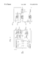
- FIG. 1 is a block diagram of a transmitter having n antennas and a receiver having j antenna, where the transmitter and the receiver operate in accordance with the principles disclosed herein;
- FIG. 1 presents a block diagram of an arrangement with a transmitter having n transmitter antenna an a receiver with j receiving antenna.
- FIG. 1 degenerates to FIG. 1 of the aforementioned 09/074,224 Alamouti et al application.
- an applied sequence of symbols c 1 , c 2 , c 3 , c 4 , c 5 , c 6 at the input of transmitter 10 results in the following sequence being sent by antennas 11 and 12 .
- the transmission can be expressed by way of the matrix [ c 1 c 2 - c 2 * c 1 * ] , ( 1 )
- h 1 is the channel coefficient from antenna 11 to antenna 21
- n t j is the noise at time t at receiver antenna j, and it is assumed to be a independent, zero mean, complex, Gaussian random variable.
- the average energy of the symbols transmitted by each of the n antennas is 1/n.
- a transmitter when a transmitter employs 8 antennas, it accumulates a frame of 8 bits and, with the beginning of the next frame, in the first time interval, the 8 antennas transmit bits c 1 ,c 2 ,c 3 ,c 4 ,c 5 ,c 6 ,c 7 ,c 8 (the first row of symbols). During the second time interval, the 8 antennas transmit bits ⁇ c 2 ,c 1 , c 4 , ⁇ c 3 ,c 6 , ⁇ c 5 , ⁇ c 8 , c 7 (the second row of symbols), etc.
- a perusal of the above matrices reveals that the rows are mere permutations of the first row, with possible different signs.
- the different signs can be expressed by letting the sign of c i in the k-th row be denoted by ⁇ k (i).
- A be a p ⁇ q matrix with terms a ij
- B be any arbitrary matrix.
- the tensor product A ⁇ circle around (x) ⁇ B is given by [ a 11 ⁇ B a 12 ⁇ B ⁇ a 1 ⁇ q ⁇ B a 21 ⁇ B a 22 ⁇ B ⁇ a 2 ⁇ q ⁇ B ⁇ ⁇ ⁇ ⁇ a p1 ⁇ B a p2 ⁇ B ⁇ a pq ⁇ B ] . ( 12 )
- Lemma For any n there exists a Hurwitz-Radon family of matrices of size ⁇ (n) ⁇ 1 whose members are integer matrices in the set ⁇ 1,0,1 ⁇ .
- a k ⁇ circle around (x) ⁇ I b ⁇ is a Hurwitz-Radon family of n ⁇ n integer matrices of size ⁇ (n) ⁇ 1.
- n 2 a .
- n 1 s 4s+3
- n 2 s 4s+4
- n 3 s 4s+5
- n 4 s 4s+6
- n 5 s 4+7 .
- matrix R is a Hurwitz-Radon integer family of size ⁇ (2) ⁇ 1, ⁇ R ⁇ circle around (x) ⁇ I 2 , P ⁇ circle around (x) ⁇ I 2 , . . . Q ⁇ circle around (x) ⁇ I 2 ⁇ is a Hurwitz-Radon integer family of size ⁇ (2 2 ) ⁇ 1, and ⁇ I 2 ⁇ circle around (x) ⁇ R ⁇ circle around (x) ⁇ I 2 , I 2 ⁇ circle around (x) ⁇ P ⁇ circle around (x) ⁇ R, Q ⁇ circle around (x) ⁇ Q ⁇ circle around (x) ⁇ R, P ⁇ circle around (x) ⁇ Q ⁇ circle around (x) ⁇ R, R ⁇ circle around (x) ⁇ P ⁇ circle around (x) ⁇ Q, R ⁇ circle around (x) ⁇ P ⁇ circle around (x) ⁇ P, R ⁇ circle around (x) ⁇ Q ⁇ circle around (x) ⁇ I 2 ⁇ is an integerHurwitz-Radon family
- equation (17) gives the transition from n 1 to n 2 .
- equation (17) gives the transition from n 1 to n 2 .
- the coefficients l 1 i ,l 2 i , . . . ,l k i are positive integers.
- G T G ( x 1 2 +x 1 2 +. . . x k 2 ) I.
- the above derivations can be employed for transmitting signals from n antennas using a generalized orthogonal design.
- a throughput of kb/p can be achieved.
- kb bits arrive at the encoder, which selects constellation symbols c 1 ,c 2 , . . . c n .
- kb bits are sent during each frame of p transmissions. It can be shown that the diversity order is nm.
- the theory of space-time coding says that for a diversity order of nm, it is possible to transmit b bits per time slot, and this is the best possible. Therefore, the rate R is defined for this coding scheme is kb/pb, or k/p.
- the following presents an approach for constructing high rate linear processing designs with low decoding complexity and full diversity order. It is deemed advantageous to take transmitter memory into account, and that means that given the rate, R, and the number of transmitting antennas, n, it is advantageous to minimize the number of time slots in a frame, p.
- A(R,n) The value of A(R,n) is the fundamental question of generalized design theory. The most interesting part of this question is the computation of A(1,n) since the generalized designes of full rate are bandwidth efficient. To address the question the following construction is offered.
- the value A(1,n) is the smaller number p such that n ⁇ (p).
- A(1,n) is a power of 2 for any n ⁇ 2.
- This full rate generalized orthogonal design has entries of the form ⁇ c 1 , ⁇ c 2 , . . . , ⁇ c p .
- ⁇ 3 [ c 1 c 2 c 3 - c 2 c 1 - c 4 - c 3 c 4 c 1 - c 4 - c 3 c 2 ] , ( 21 )
- ⁇ 5 [ c 1 c 2 c 3 c 4 c 5 - c 2 c 1 c 4 - c 3 c 6 - c 3 - c 4 c 1 c 2 c 7 - c 4 c 3 - c 2 c 1 c 8 - c 5 - c 6 - c 7 - c 8 c 1 - c 6 c 5 - c 8 c 7 - c 8 c 7 - c 8 c 7 - c 2 - c 7 c 8 c 5 - c 6
Abstract
It is possible to realize a transmitter where a block of n symbols is encoded through an n×n matrix and transmitted over n antennas in n time intervals, only for n=2, 4, or 8. For all other numbers of antennas, the disclosed methodology permits the realization of full-rate rectangular designs, where the number of time intervals, p, is greater than n. In particular, the number of time intervals, p, is such that ρ(p)≧n, where ρ(p)=8c+2d, where c and d are such that p=b·24c+d, and b is an odd integer. Complex symbols can also be handled, but the rate for a design that allows use of any number of antennas is 0.5.
Description
This application claims the benefit of U.S. Provisional Application No. 60/065,095, filed Nov. 11, 1997; and of U.S. Provisional Application No. 60/076,613, filed Mar. 3, 1998.
This invention relates to wireless communication and, more particularly, to techniques for effective wireless communication in the presence of fading and other degradations.
The most effective technique for mitigating multipath fading in a wireless radio channel is to cancel the effect of fading at the transmitter by controlling the transmitter's power. That is, if the channel conditions are known at the transmitter (on one side of the link), then the transmitter can pre-distort the signal to overcome the effect of the channel at the receiver (on the other side). However, there are two fundamental problems with this approach. The first problem is the transmitter's dynamic range. For the transmitter to overcome an ×dB fade, it must increase its power by ×dB which, in most cases, is not practical because of radiation power limitations, and the size and cost of amplifiers. The second problem is that the transmitter does not have any knowledge of the channel as seen by the receiver (except for time division duplex systems, where the transmitter receives power from a known other transmitter over the same channel). Therefore, if one wants to. control a transmitter based on channel characteristics, channel information has to be sent from the receiver to the transmitter, which results in throughput degradation and added complexity to both the transmitter and the receiver.
Other effective techniques are time and frequency diversity. Using time interleaving together with coding can provide diversity improvement. The same holds for frequency hopping and spread spectrum. However, time interleaving results in unnecessarily large delays when the channel is slowly varying. Equivalently, frequency diversity techniques are ineffective when the coherence bandwidth of the channel is large (small delay spread).
It is well known that in most scattering environments antenna diversity is the most practical and effective technique for reducing the effect of multipath fading. The classical approach to antenna diversity is to use multiple antennas at the receiver and perform combining (or selection) to improve the quality of the received signal.
The major problem with using the receiver diversity approach in current wireless communication systems, such as IS-136 and GSM, is the cost, size and power consumption constraints of the receivers. For obvious reasons, small size, weight and cost are paramount. The addition of multiple antennas and RF chains (or selection and switching circuits) in receivers is presently not be feasible. As a result, diversity techniques have often been applied only to improve the up-link (receiver to base) transmission quality with multiple antennas (and receivers) at the base station. Since a base station often serves thousands of receivers, it is more economical to add equipment to base stations rather than the receivers
Recently, some interestingapproaches for transmitter diversity have been suggested. A delay diversity scheme was proposed by A. Wittneben in “Base Station Modulation Diversity for Digital SIMULCAST,” Proceeding of the 1991 IEEE Vehicular Technology Conference (VTC 41 st), PP. 848-853, May 1991, and in “A New Bandwidth Efficient Transmit Antenna Modulation Diversity Scheme For Linear Digital Modulation,” in Proceeding of the 1993 IEEE International Conference on Communications (IICC '93), PP. 1630-1634, May 1993. The proposal is for a base station to transmit a sequence of symbols through one antenna, and the same sequence of symbols—but delayed—through another antenna.
U.S. Pat. No. 5,479,448, issued to Nambirajan Seshadri on Dec. 26, 1995, discloses a similar arrangement where a sequence of codes is transmitted through two antennas. The sequence of codes is routed through a cycling switch that directs each code to the various antennas, in succession. Since copies of the same symbol are transmitted through multiple antennas at different times, both space and time diversity are achieved. A maximum likelihood sequence estimator (MLSE) or a minimum mean squared error (MMSE) equalizer is then used to resolve multipath distortion and provide diversity gain. See also N. Seshadri, J. H. Winters, “Two Signaling Schemes for Improving the Error Performance of FDD Transmission Systems Using Transmitter Antenna Diversity,” Proceeding of the 1993 IEEE Vehicular Technology Conference (VTC 43rd), pp. 508-511, May 1993; and J. H. Winters, “The Diversity Gain of Transmit Diversity in Wireless Systems with Rayleigh Fading,” Proceeding of the 1994 ICC/SUPERCOMM, New Orleans, Vol. 2, PP. 1121-1125, May 1994.
Still another interesting approach is disclosed by Tarokh, Seshadri, Calderbank and Naguib in U.S. application, Ser. No. 08/847635, filed Apr. 25, 1997 (based on a provisional application filed Nov. 7, 1996), where symbols are encoded according to the antennas through which they are simultaneously transmitted, and are decoded using a maximum likelihood decoder. More specifically, the process at the transmitter handles the information in blocks of M1 bits, where M1 is a multiple of M2, i.e., M1=k*M2. It converts each successive group of M2 bits into information symbols (generating thereby k information symbols), encodes each sequence of k information symbols into n channel codes (developing thereby a group of n channel codes for each sequence of k information symbols), and applies each code of a group of codes to a different antenna.
Recently, a powerful approach is disclosed by Alamouti et al in U.S. patent application Ser. No. 09/074,224, filed May 5, 1998, and titled “Transmitter Diversity Technique for Wireless Communication”. This disclosure revealed that an arrangement with two transmitter antennas can be realized that provides diversity with bandwidth efficiency, easy decoding at the receiver (merely linear processing), and performance that is the same as the performance of maximum ratio combining arrangements. In this arrangement the constellation has four symbols, and a frame has two time slots during which two bits arrive. Those bit are encoded so that in a first time slot symbol c1 and c2 are sent by the first and second antennas, respectively, and in a second time slot symbols—c2* and c1* are sent by the first and second antennas, respectively. Accordingly, this can be expressed by an equation of the form r=Hc+n, where r is a vector of signals received in the two time slots, c is a vector of symbols c1 and c2, n is a vector of received noise signals in the two time slots, and H is an orthogonal matrix that reflects the above-described constellation of symbols.
The good performance of this disclosed approach forms an impetus for finding other systems, with a larger number of transmit antennas, that has equally good performance.
The prior art teachings for encoding signals and transmitting them over a plurality of antennas are advanced by disclosing a method for encoding for any number of transmitting antennas. It is demonstrated that for square designs, where a block of n real symbols is permuted n times (with some sign reversals), and at each time interval the permuted block of n symbols is respectively transmitted over the n antennas, a design can be realized only for n=2, 4, or 8. For all other numbers of antennas, the disclosed methodology permits the realization of full-rate rectangular designs, where the number of time intervals, p, is greater than n. In particular, the number of time intervals, p, is such that ρ(p)≧n, where ρ(p)=8c+2d, where c and d are such that p=b·24c+d, and b is an odd integer. Complex symbols can also be handled, but the rate for a design that allows use of any number of antennas is 0.5.
FIG. 1 is a block diagram of a transmitter having n antennas and a receiver having j antenna, where the transmitter and the receiver operate in accordance with the principles disclosed herein;
FIG. 1 presents a block diagram of an arrangement with a transmitter having n transmitter antenna an a receiver with j receiving antenna. When n=2, FIG. 1 degenerates to FIG. 1 of the aforementioned 09/074,224 Alamouti et al application. In that application an applied sequence of symbols c1, c2, c3, c4, c5, c6 at the input of transmitter 10 results in the following sequence being sent by antennas 11 and 12.
| Time: | t | t + T | t + 2T | t + 3T | t + 4T | t + 5T | |
| Antenna 11 | c0 | −c1* | c2 | −c3* | c4 | −c5* | . . . |
| Antenna 12 | c1 | c0* | c3 | c2* | c5 | c4* | . . . |
The transmission can be expressed by way of the matrix 
where the columns represent antennas, and the rows represent time of transmission. The corresponding received signal (ignoring the noise) is:
| Time: | t | t + T | t + 2T | t + 3T | |
| Antenna 11 | h1c1 + h2c2 | −h1c2* + h2c1* | h1c3 + h2c4 | −h1c4* + h2c3* | . . . |
where h1 is the channel coefficient from antenna 11 to antenna 21, and h2 is the channel coefficient from antenna 12 to antenna 21, which can also be in the form 
Extending this to n antennas at the base station and m antennas in the remote units, the signal rt j represents the signal received at time t by antenna j, and it is given by 
where nt j is the noise at time t at receiver antenna j, and it is assumed to be a independent, zero mean, complex, Gaussian random variable. The average energy of the symbols transmitted by each of the n antennas is 1/n.
Assuming a perfect knowledge of the channel coefficients, hij, from transmit antenna i to receive antenna j, the receiver's decision metric is 
Over all codewords c1 1c1 2 . . . c1 nc2 1c2 2 . . . c2 n . . . c1 1c1 2 . . . c1 n and decides in favor of the codeword that minimizes this sum.
For a constellation with real symbols, what is desired is a matrix of size n that is orthogonal, with intermediates ±c1,±c2, . . . ±Cn. The existence problem for orthogonal designs is known in the mathematics literature as the Hurwitz-Radon problem, and was completely settled by Radon at the beginning of the 20th century. What has been shown is that an orthogonal design exists if and only if n=2, 4 or 8.
Indeed, such a matrix can be designed for the FIG. 1 system for n=2, 4 or 8, by employing, for example, the matrices 
What that means, for example, is that when a transmitter employs 8 antennas, it accumulates a frame of 8 bits and, with the beginning of the next frame, in the first time interval, the 8 antennas transmit bits c1,c2,c3,c4,c5,c6,c7,c8 (the first row of symbols). During the second time interval, the 8 antennas transmit bits −c2,c1, c4,−c3,c6,−c5,−c8, c7 (the second row of symbols), etc.
A perusal of the above matrices reveals that the rows are mere permutations of the first row, with possible different signs. The permutations can be denoted by εk (p) such that εk (p)=q means that in row k, the symbol cp appears in column q. The different signs can be expressed by letting the sign of ci in the k-th row be denoted by δk (i).
It can be shown that minimizing the metric of equation (4) is equivalent to minimizing the following sum that εk (p)=q means that in row k, the symbol cp appears in column q. The different signs can be expressed by letting the sign of ci in the k-th row be denoted by δk (i).
It can be shown that minimizing the metric of equation (4) is equivalent to minimizing the following sum 
Since the term 
only depends on ci, on the channel coefficients, and on the permutations and signs of the matrix, it follows that minimizing the outer sum (over the summing index i) amounts to minimizing each of the terms for 1≦i≦n. Thus, the maximum likelihood detection rule is to form the decision variable 
for all transmitting antennas, i=1,2, . . . n, and decide in favor of is made in favor of symbol ci from among all constellation symbols if 
This is a very simple decoding strategy that provides diversity.
There are two attractions in providing transmit diversity via orthogonal designs.
There is no loss in bandwidth, in the sense that orthogonal designs provide the maximum possible transmission rate at full diversity.
There is an extremely simple maximum likelihood decoding algorithm which only uses linear combining at the receiver. The simplicity of the algorithm comes from the orthogonality of the columns of the orthogonal design.
The above properties are preserved even if linear processing at the transmitter is allowed. Therefore, in accordance with the principles disclosed herein, the definition of orthogonal arrays is relaxed to allow linear processing at the transmitter. Signals transmitted from different antennas will now be linear combinations of constellation symbols.
B i T B i =I
It has been shown by Radon that when n=2ab, where b is odd and a=4c+d with 0≦d<4 and 0≦c, then and Hurwitz-Radon family of n×n matrices contains less than ρ(n)=8c+2d≦n matrices (the maximum number of member in the family is ρ(n)−1). A Hurwitz-Radon family that contains n−1 matrices exists if and only if n=2,4, or 8.
Definition: Let A be a p×q matrix with terms aij, and let B be any arbitrary matrix. The tensor product A{circle around (x)}B is given by 
Lemma: For any n there exists a Hurwitz-Radon family of matrices of size ρ(n)−1 whose members are integer matrices in the set {−1,0,1}.
Proof: The proof is by explicit construction. Let Ib denote the identity matrix of size b. We first notice that if n=2ab with b odd, then since ρ(n) is independent of b (ρ(n)=8c+2d) it follows that ρ(n)=ρ(2a). Moreover, given a family of 2a×2a Hurwitz-Radon integer matrices {A1, A2, . . . Ak} of size s=ρ(2a)−1, the set {A1{circle around (x)}Ih, A2{circle around (x)}Ib, . . . Ak{circle around (x)}Ib} is a Hurwitz-Radon family of n×n integer matrices of size ρ(n)−1. In light of this observation, it suffices to prove the lemma for n=2a. To this end, we may choose a set of Hurwitz-Radon matrices, such as 
and let n1=s4s+3, n2=s4s+4, n3=s4s+5, n4=s4s+6, and n5=s4+7. Then,
ρ(n 2)=ρ(n 1)+1
One can observe that matrix R is a Hurwitz-Radon integer family of size ρ(2)−1, {R{circle around (x)}I2, P{circle around (x)}I2, . . . Q{circle around (x)}I2} is a Hurwitz-Radon integer family of size ρ(22)−1, and {I2{circle around (x)}R{circle around (x)}I2, I2{circle around (x)}P{circle around (x)}R, Q{circle around (x)}Q{circle around (x)}R, P{circle around (x)}Q{circle around (x)}R, R{circle around (x)}P{circle around (x)}Q, R{circle around (x)}P{circle around (x)}P, R{circle around (x)}Q{circle around (x)}I2} is an integerHurwitz-Radon family of size ρ(23)−1. Extending from the above, one can easily verify that if {A1, A2, . . . Ak} is an integer Hurwitz-Radon family of n×n matrices, then
is an integer Hurwitz-Radon family of s+1 integer matrices (2n×2n).
If, in addition, {L1, L2, . . . Lm} is an integer Hurwitz-Radon family of k×k matrices, then
is an integer Hurewitz-Radon family of s+m+1 integer matrices (2nk×2nk).
With a family of integer Hurwitz-Radon matrices with size ρ(23)−1 constructed for n=23, with entries in the set {−1, 0, 1}, equation (17) gives the transition from n1 to n2. By using (18) and letting k=n1 and n=2, we get the transition from n1 to n3. Similarly, with k=n1 and n=4 we get the transition from n1 to n3 and with k=n1 and n=8 we get the transition from n1 to n5.
The simple maximum likelihood decoding algorithm described above is achieved because of the orthogonality of columns of the design matrix. Thus, a more generalized definition of orthogonal design may be tolerated. Not only does this create new and simple transmission schemes for any number of transmit antennas, but also generalizes the Hurwitz-Radon theory to non-square matrices.
Definition: A generalized orthogonal design G of size n is a p×n matrix with entries 0,±x1,±x2, . . . ,±xk such that GTG=D is a diagonal matrix with diagonal Dij, i=1,2, . . . ,n of the form (l1 tx1 2+l2 ix2 2+. . . +lk ixk 2). The coefficients l1 i,l2 i, . . . ,lk i, are positive integers. The rate of G is R=k/p.
Theorem: A p×n generalized orthogonal design ε in variables x1, x2, . . . xk exists if and only if there exists a generalized orthogonal design G in the same variables and of the same size such that GTG=(x1 2+x1 2+. . . xk 2)I.
In view of the above theorem, without loss of generality, one can assume that any p×n generalized orthogonal design G in variable x1,x2, . . . xk satisfies
The above derivations can be employed for transmitting signals from n antennas using a generalized orthogonal design.
Considering a constellation A of size 2b, a throughput of kb/p can be achieved. At time slot 1, kb bits arrive at the encoder, which selects constellation symbols c1,c2, . . . cn. The encoder populates the matrix by setting xi=ci, and at times t=1,2, . . . , p the signals Gt1,Gt2, . . . Gm are transmitted simultaneously from antennas 1,2, . . . ,n. That is the transmission matrix design is 
Thus, kb bits are sent during each frame of p transmissions. It can be shown that the diversity order is nm. The theory of space-time coding says that for a diversity order of nm, it is possible to transmit b bits per time slot, and this is the best possible. Therefore, the rate R is defined for this coding scheme is kb/pb, or k/p.
The following presents an approach for constructing high rate linear processing designs with low decoding complexity and full diversity order. It is deemed advantageous to take transmitter memory into account, and that means that given the rate, R, and the number of transmitting antennas, n, it is advantageous to minimize the number of time slots in a frame, p.
Definition: For a given pair (R,n), A(R,n) is the minimum number p such that there exists a p×n generalized design with rate at least. If no such design exists, then A(R,n)=∞.
The value of A(R,n) is the fundamental question of generalized design theory. The most interesting part of this question is the computation of A(1,n) since the generalized designes of full rate are bandwidth efficient. To address the question the following construction is offered.
Construction I: Let X=(x1,x2, . . . ,xp) and n≦ρ(p). In the discussion above, a family of integer p×p matrices with ρ(p)−1 with members {A1,A2, . . . Aρ(p)−1} was constructed (Lemma following equation 12). That is, the members Ai are in the set {−1,0,1}. Let A0=I and consider the p×n matrix G whose j-th column is Aj−1XT for j=1,2, . . . ,n. The Hurwitz-Radon conditions imply that G is a generalized orthogonal design of full rate.
From the above, a number of facts can be ascertained:
The value A(1,n) is the smaller number p such that n≦ρ(p).
The value of A(1,n) is a power of 2 for any n≧2.
The value A(1,n)=min(24c+d) where the minimization is taken over the set {c,d|0≦c,0≦d<4 and 8c+2d≧n}.
A(1,2)=2, A(1,3)=A(1,4)=4, and A(1,n)=8 for 5≦n≦8.
Orthogonal designs are delay optical for n=2,4, and 8.
For any R, A(R,n)<∞.
The above explicitly constructs a Hurwitz-Radon family of matrices of size p with ρ(p) members such that all the matrices in the family have entries in the set {−1,0,1}. Having such a family of Hurwitz-Radon matrices of size p=A(1,n), we can apply Construction I to provide a p×n generalized orthogonal design with full rate.
This full rate generalized orthogonal design has entries of the form ±c1,±c2, . . . ,±cp. Thus, for a transmitter having n≦8 transmit antennas the following optimal generalized designs of rate one are: 
The simple transmit diversity schemes disclosed above are for a real signal constellation. A design for a complex constellation is also possible. A complex orthogonal design of size n that is contemplated here is a unitary matrix whose entries are indeterminates ±c1,±c2, . . . ,±cn, their complex conjugates ±c1*,±c2*, . . . ,±cn*, or these indeterminates multiplied by ±i, where i={square root over (−1)}. Without loss of generality, we may select the first row to be c1,c2, . . . ,cn.
It can be shown that half rate (R=0.5) complex generalized orthogonal designs exist. They can be constructed by creating a design as described above for real symbols, and repeat the rows, except that each symbol is replaced by its complex conjugate. Stated more formally, given that a design needs to be realized for complex symbols, we can replace each complex variable ci=c1+ici, where i={square root over (−1)}, by the 2×2 real matrix 
It is easy to see that a matrix formed in this way is a real orthogonal design. The following presents half rate codes for transmission using three and four transmit antennas by, of course, an extension to any number of transmitting antennas follows directly from application of the principles disclosed above. 
These transmission schemes and their analogs for higher values of n not only give full diversity but give 3 dB extra coding gain over the uncoded, but they lose half of the theoretical bandwidth efficiency.
Some designs are available that provide a rate that is higher than 0.5. The following presents designs for rate 0.75 for n=3 and n=4. 
Claims (25)
1. A transmitter responsive to a stream of symbols comprising:
n antennas, where n≧2; and
an encoder for delivering p sets of n symbols to said n antennas, to be transmitted in p time intervals, where
p>n,
symbols delivered to each antenna in said p time intervals form temporal sets, and
said temporal sets are orthogonal to each other.
2. The transmitter of claim 1 where p is expressible by p=b·24c+d, b being an odd integer, 0≦d<4 and 0≦c, and p is such that 8c+2d≧n.
3. The transmitter of claim 1 further comprising a buffer for storing at least n symbols.
4. The transmitter of claim 1 where the symbols are real.
5. The transmitter of claim 1 where the sets of symbols are permutations of each other, with selected sign reversals.
6. A transmitter responsive to a stream of symbols comprising:
n antennas; and
an encoder for delivering p sets of n symbols to said n antennas, to be transmitted in p time intervals, where p is expressible by p=b·24c+d, where b is an odd integer, 0≦d<4 and 0≦c, and p is such that 8c+2d≧n.
7. The transmitter of claim 6 where symbols delivered to each antenna in said p time intervals form temporal sets, and said temporal sets are orthogonal to each other.
8. The transmitter of claim 6 further comprising a buffer for storing at least n symbols.
9. The transmitter of claim 6 where the symbols are real.
10. The transmitter of claim 6 where the sets of symbols are permutations of each other, with selected sign reversals.
11. A transmitter responsive to a stream of complex symbols comprising:
n antennas; and
an encoder for delivering 2p sets of n symbols to said n antennas, to be transmitted in 2p time intervals, where p is expressible by p=b·24c+d, where b is an odd integer, 0≦d<4 and 0≦c , and where p is such that 8c+2d≧n.
12. The transmitter of claim 11 where p of the sets of symbols are permutations of the symbols, with selected sign reversals, and remaining p of the sets of symbols are repeats of the permutations and of the selected sign reversals, but with the symbols replaced by their respective complex conjugates.
13. The transmitter of claim 11 where symbols delivered to each antenna in said 2p time intervals form temporal sets, and said temporal sets are orthogonal to each other.
14. The transmitter of claim 1 where the p sets of n symbols, when viewed as a matrix, form a matrix of p rows and n columns of symbols c, the form 
15. The transmitter of claim 1 where the p sets of n symbols, when viewed as a matrix, form a matrix of p rows and n columns of symbols c, the form 
16. The transmitter of claim 1 where the p sets of n symbols, when viewed as a matrix, form a matrix of p rows and n columns of symbols c, the form 
17. The transmitter of claim 1 where the p sets of n symbols, when viewed as a matrix, form a matrix of p rows and n columns of symbols c, the form 
18. The transmitter of claim 11 where the 2p sets of n symbols, when viewed as a matrix, form a matrix of 2p rows and n columns of symbols c, the form 
19. The transmitter of claim 11 where the 2p sets of n symbols, when viewed as a matrix, form a matrix of 2p rows and n columns of symbols c, the form 
20. A transmitter responsive to a stream of complex symbols comprising:
three antennas; and
an encoder for delivering four sets of three symbols to said three antennas, to be transmitted in four time intervals, where the four sets of three symbols, when viewed as a matrix, form the matrix 
21. A transmitter responsive to a stream of complex symbols comprising:
four antennas; and
an encoder for delivering four sets of four symbols to said three antennas, to be transmitted in four time intervals, where the four sets of four symbols, when viewed as a matrix, form the matrix 
22. A transmitter comprising:
n antennas; and
an encoder for delivering p sets of n symbols to said n antennas, to be transmitted in p time intervals, thus transmitting n sets of p symbols c1,c2, . . . cp with a chosen set of respective signs, and where each of said n sets is constructed by forming a product Aic, i=1,2, . . . ,n and the set Ai's is a set of Hurwitz-Radon matrices.
23. The transmitter of claim 22 where the set of Ai's is constructed from tensor products of three Hurwitz-Radon 2×2 matrices.
24. The transmitter of claim 23 where the three 2×2 matrices are 
25. A transmitter comprising
an encoder for encoding blocks of p symbols, where p is a power of 2, expressible by p=24c+d, where 0≦d<4 and 0≦c, and
n antennas for simultaneously transmitting a different one of said symbols over said n antennas, and
means for transmitting said block of symbols in p time intervals, where
n≧2,
p>n, and
n is such that 8c+2d≧n.
Priority Applications (1)
| Application Number | Priority Date | Filing Date | Title |
|---|---|---|---|
| US09/186,908 US6430231B1 (en) | 1997-11-11 | 1998-11-06 | Generalized orthogonal designs for space-time codes for wireless communication |
Applications Claiming Priority (3)
| Application Number | Priority Date | Filing Date | Title |
|---|---|---|---|
| US6509597P | 1997-11-11 | 1997-11-11 | |
| US7661398P | 1998-03-03 | 1998-03-03 | |
| US09/186,908 US6430231B1 (en) | 1997-11-11 | 1998-11-06 | Generalized orthogonal designs for space-time codes for wireless communication |
Publications (1)
| Publication Number | Publication Date |
|---|---|
| US6430231B1 true US6430231B1 (en) | 2002-08-06 |
Family
ID=27370728
Family Applications (1)
| Application Number | Title | Priority Date | Filing Date |
|---|---|---|---|
| US09/186,908 Expired - Lifetime US6430231B1 (en) | 1997-11-11 | 1998-11-06 | Generalized orthogonal designs for space-time codes for wireless communication |
Country Status (1)
| Country | Link |
|---|---|
| US (1) | US6430231B1 (en) |
Cited By (24)
| Publication number | Priority date | Publication date | Assignee | Title |
|---|---|---|---|---|
| US20010031018A1 (en) * | 1998-12-31 | 2001-10-18 | Mohammed Nafie | Block level space time transmit diversity in wireless communications |
| US6560295B1 (en) * | 1999-09-15 | 2003-05-06 | Hughes Electronics Corporation | Method of generating space-time codes for generalized layered space-time architectures |
| US6584593B1 (en) * | 1998-10-02 | 2003-06-24 | At&T Corp. | Concatenation of turbo-TCM with space-block coding |
| US20040014431A1 (en) * | 2002-06-05 | 2004-01-22 | Titus Lo | Adaptive communications system and method |
| US6778619B2 (en) * | 2001-05-11 | 2004-08-17 | Ericsson Inc. | Methods for receiving diversity transmissions including prefiltering to provide minimum phase channel characteristics and related receivers |
| US20040234003A1 (en) * | 1997-09-16 | 2004-11-25 | Siavash Alamouti | Transmitter diversity technique for wireless communications |
| US6834043B1 (en) * | 2000-07-24 | 2004-12-21 | Motorola, Inc. | Method and device for exploiting transmit diversity in time varying wireless communication systems |
| US20050009476A1 (en) * | 2003-07-07 | 2005-01-13 | Shiquan Wu | Virtual MIMO transmitters, receivers, systems and methods |
| US20050105630A1 (en) * | 1997-10-31 | 2005-05-19 | Siavash Alamouti | Low complexity maximum likelihood detection of concatenate space codes for wireless applications |
| US6922447B1 (en) * | 2000-05-17 | 2005-07-26 | Nokia Corporation | Apparatus, and associated method, for forming a signal exhibiting space-time redundancy |
| US20050163246A1 (en) * | 1999-02-10 | 2005-07-28 | Hamid Jafarkhani | Differential transmitter diversity technique for wireless communications |
| US6959048B1 (en) * | 1999-10-19 | 2005-10-25 | Nokia Networks Oy | Optimizing link quality by space and time interleaving |
| US20060018403A1 (en) * | 2004-07-26 | 2006-01-26 | Nec Laboratories America, Inc. | Optimized high rate space-time codes for wireless communication |
| US7065156B1 (en) * | 2000-08-31 | 2006-06-20 | Nokia Mobile Phones Ltd. | Hopped delay diversity for multiple antenna transmission |
| US20060245409A1 (en) * | 1999-07-09 | 2006-11-02 | Sari Korpela | Method for transmitting a sequence of symbols |
| US7154970B1 (en) * | 1999-02-10 | 2006-12-26 | At&T Corp. | Differential transmitter diversity technique for wireless communications |
| US7274752B2 (en) | 1998-09-17 | 2007-09-25 | Cingular Wireless Ii, Llc | Maximum ratio transmission |
| US20080037685A1 (en) * | 2001-05-25 | 2008-02-14 | Regents Of The University Of Minnesota | Space-time coded transmissions within a wireless communication network |
| US20080101304A1 (en) * | 2006-10-31 | 2008-05-01 | Alfred Joseph A | Method and apparatus for providing broadband signals to a portable user device |
| US20100124917A1 (en) * | 2008-11-18 | 2010-05-20 | Miller Robert R Ii | Space time coding where space diversity derives from use of multiple base stations |
| US20100195761A1 (en) * | 2004-04-23 | 2010-08-05 | France Telecom | Method and device for transmitting a signal in a multi-antenna system, signal, and method for estimating the corresponding transmission channels |
| US20110026629A1 (en) * | 2009-07-28 | 2011-02-03 | Ehsan Nekoui | System and method for encoding and decoding of space-time block codes in data communication |
| USRE42219E1 (en) | 1998-11-24 | 2011-03-15 | Linex Technologies Inc. | Multiple-input multiple-output (MIMO) spread spectrum system and method |
| KR101100116B1 (en) | 2010-05-28 | 2011-12-29 | 고려대학교 산학협력단 | Apparatus for transmiter processing precoding using the number of transmiter antenna in open loop communication system and method for the same |
Citations (1)
| Publication number | Priority date | Publication date | Assignee | Title |
|---|---|---|---|---|
| US6185258B1 (en) * | 1997-09-16 | 2001-02-06 | At&T Wireless Services Inc. | Transmitter diversity technique for wireless communications |
-
1998
- 1998-11-06 US US09/186,908 patent/US6430231B1/en not_active Expired - Lifetime
Patent Citations (1)
| Publication number | Priority date | Publication date | Assignee | Title |
|---|---|---|---|---|
| US6185258B1 (en) * | 1997-09-16 | 2001-02-06 | At&T Wireless Services Inc. | Transmitter diversity technique for wireless communications |
Cited By (59)
| Publication number | Priority date | Publication date | Assignee | Title |
|---|---|---|---|---|
| US7587007B2 (en) | 1997-09-16 | 2009-09-08 | At&T Mobility Ii Llc | Transmitter diversity technique for wireless communications |
| US20080063107A1 (en) * | 1997-09-16 | 2008-03-13 | At&T Mobility Ii Llc | Transmitter diversity technique for wireless communications |
| US20110170635A1 (en) * | 1997-09-16 | 2011-07-14 | Siavash Alamouti | Transmitter diversity technique for wireless communications |
| US9203499B2 (en) | 1997-09-16 | 2015-12-01 | At&T Mobility Ii Llc | Transmitter diversity technique for wireless communications |
| US7120200B2 (en) * | 1997-09-16 | 2006-10-10 | Cingular Wireless Ii, Llc | Transmitter diversity technique for wireless communications |
| US7386077B2 (en) | 1997-09-16 | 2008-06-10 | At&T Mobility Ii Llc | Receiver diversity technique for wireless communications |
| US20040234003A1 (en) * | 1997-09-16 | 2004-11-25 | Siavash Alamouti | Transmitter diversity technique for wireless communications |
| US20070110179A1 (en) * | 1997-09-16 | 2007-05-17 | Cingular Wireless Ii, Llc | Transmitter diversity technique for wireless communications |
| US8355475B2 (en) | 1997-09-16 | 2013-01-15 | At&T Mobility Ii Llc | Diversity technique for wireless communications |
| US7916806B2 (en) | 1997-09-16 | 2011-03-29 | At&T Mobility Ii Llc | Transmitter diversity technique for wireless communications |
| US20080008275A1 (en) * | 1997-09-16 | 2008-01-10 | Cingular Wireless Ii, Llc | Transmitter diversity technique for wireless communications |
| US9749032B2 (en) | 1997-09-16 | 2017-08-29 | At&T Mobility Ii Llc | Transmitter diversity technique for wireless communications |
| US8731107B2 (en) | 1997-10-31 | 2014-05-20 | At&T Mobility Ii Llc | Low complexity maximum likelihood detection of concatenated space codes for wireless applications |
| US7643568B2 (en) | 1997-10-31 | 2010-01-05 | At&T Mobility Ii Llc | Low complexity maximum likelihood detection of concatenated space codes for wireless applications |
| US8351545B2 (en) | 1997-10-31 | 2013-01-08 | At&T Mobility Ii Llc | Low complexity maximum likelihood detection of concatenated space codes for wireless applications |
| US20050105630A1 (en) * | 1997-10-31 | 2005-05-19 | Siavash Alamouti | Low complexity maximum likelihood detection of concatenate space codes for wireless applications |
| US9065516B2 (en) | 1997-10-31 | 2015-06-23 | At&T Mobility Ii, Llc | Low complexity maximum likelihood detection of concatenated space codes for wireless applications |
| US7274752B2 (en) | 1998-09-17 | 2007-09-25 | Cingular Wireless Ii, Llc | Maximum ratio transmission |
| US7362823B2 (en) | 1998-09-17 | 2008-04-22 | Cingular Wireless Ii, Llc | Maximum ratio transmission |
| US20080144739A1 (en) * | 1998-09-17 | 2008-06-19 | At&T Mobility Ii Llc | Maximum ratio transmission |
| US7609771B2 (en) | 1998-09-17 | 2009-10-27 | At&T Mobility Ii Llc | Maximum ratio transmission |
| US8520746B2 (en) | 1998-09-17 | 2013-08-27 | At&T Mobility Ii Llc | Maximum ratio transmission |
| US6584593B1 (en) * | 1998-10-02 | 2003-06-24 | At&T Corp. | Concatenation of turbo-TCM with space-block coding |
| USRE42219E1 (en) | 1998-11-24 | 2011-03-15 | Linex Technologies Inc. | Multiple-input multiple-output (MIMO) spread spectrum system and method |
| USRE43812E1 (en) | 1998-11-24 | 2012-11-20 | Linex Technologies, Inc. | Multiple-input multiple-output (MIMO) spread-spectrum system and method |
| US20050058216A9 (en) * | 1998-12-31 | 2005-03-17 | Mohammed Nafie | Block level space time transmit diversity in wireless communications |
| US20010031018A1 (en) * | 1998-12-31 | 2001-10-18 | Mohammed Nafie | Block level space time transmit diversity in wireless communications |
| US7088785B2 (en) * | 1998-12-31 | 2006-08-08 | Texas Instruments Incorporated | Block level space time transmit diversity in wireless communications |
| US7164729B2 (en) * | 1999-02-10 | 2007-01-16 | At&T Corp. | Differential transmitter diversity technique for wireless communications |
| US7154970B1 (en) * | 1999-02-10 | 2006-12-26 | At&T Corp. | Differential transmitter diversity technique for wireless communications |
| US20050163246A1 (en) * | 1999-02-10 | 2005-07-28 | Hamid Jafarkhani | Differential transmitter diversity technique for wireless communications |
| US20060245409A1 (en) * | 1999-07-09 | 2006-11-02 | Sari Korpela | Method for transmitting a sequence of symbols |
| US7724720B2 (en) * | 1999-07-09 | 2010-05-25 | Nokia Corporation | Method for transmitting a sequence of symbols |
| US20030194022A1 (en) * | 1999-09-15 | 2003-10-16 | Hughes Electronics Corporation | Method of generating space-time codes for generalized layered space-time architectures |
| US7012967B2 (en) * | 1999-09-15 | 2006-03-14 | Hammons Jr A Roger | Method of generating space-time codes for generalized layered space-time architectures |
| US6560295B1 (en) * | 1999-09-15 | 2003-05-06 | Hughes Electronics Corporation | Method of generating space-time codes for generalized layered space-time architectures |
| US6959048B1 (en) * | 1999-10-19 | 2005-10-25 | Nokia Networks Oy | Optimizing link quality by space and time interleaving |
| US6922447B1 (en) * | 2000-05-17 | 2005-07-26 | Nokia Corporation | Apparatus, and associated method, for forming a signal exhibiting space-time redundancy |
| US6834043B1 (en) * | 2000-07-24 | 2004-12-21 | Motorola, Inc. | Method and device for exploiting transmit diversity in time varying wireless communication systems |
| US7065156B1 (en) * | 2000-08-31 | 2006-06-20 | Nokia Mobile Phones Ltd. | Hopped delay diversity for multiple antenna transmission |
| US6778619B2 (en) * | 2001-05-11 | 2004-08-17 | Ericsson Inc. | Methods for receiving diversity transmissions including prefiltering to provide minimum phase channel characteristics and related receivers |
| US20080037685A1 (en) * | 2001-05-25 | 2008-02-14 | Regents Of The University Of Minnesota | Space-time coded transmissions within a wireless communication network |
| US7609782B2 (en) * | 2001-05-25 | 2009-10-27 | Regents Of The University Of Minnesota | Space-time coded transmissions within a wireless communication network |
| US20040014431A1 (en) * | 2002-06-05 | 2004-01-22 | Titus Lo | Adaptive communications system and method |
| US7181246B2 (en) * | 2002-06-05 | 2007-02-20 | Neocific, Inc. | Adaptive communications system and method |
| WO2005004351A1 (en) * | 2003-07-07 | 2005-01-13 | Nortel Networks Limited | Virtual mimo transmitters, receivers, systems and methods |
| US20050009476A1 (en) * | 2003-07-07 | 2005-01-13 | Shiquan Wu | Virtual MIMO transmitters, receivers, systems and methods |
| US20100195761A1 (en) * | 2004-04-23 | 2010-08-05 | France Telecom | Method and device for transmitting a signal in a multi-antenna system, signal, and method for estimating the corresponding transmission channels |
| US8358990B2 (en) * | 2004-04-23 | 2013-01-22 | France Telecom | Method and device for transmitting a signal in a multi-antenna system, signal, and method for estimating the corresponding transmission channels |
| US20060018403A1 (en) * | 2004-07-26 | 2006-01-26 | Nec Laboratories America, Inc. | Optimized high rate space-time codes for wireless communication |
| US7366248B2 (en) | 2004-07-26 | 2008-04-29 | Nec Laboratories America, Inc. | Optimized high rate space-time codes for wireless communication |
| US8155583B2 (en) | 2006-10-31 | 2012-04-10 | At&T Intellectual Property Ii, L.P. | Method and apparatus for providing broadband signals to a portable user device |
| US20080101304A1 (en) * | 2006-10-31 | 2008-05-01 | Alfred Joseph A | Method and apparatus for providing broadband signals to a portable user device |
| US8811889B2 (en) | 2006-10-31 | 2014-08-19 | At&T Intellectual Property Ii, L.P. | Method and apparatus for providing broadband signals to a portable user device |
| US8385904B2 (en) | 2008-11-18 | 2013-02-26 | At&T Intellectual Property Ii, L.P. | Space time coding where space diversity derives from use of multiple base stations |
| US20100124917A1 (en) * | 2008-11-18 | 2010-05-20 | Miller Robert R Ii | Space time coding where space diversity derives from use of multiple base stations |
| US8094751B2 (en) * | 2009-07-28 | 2012-01-10 | Ehsan Nekoui | System and method for encoding and decoding of space-time block codes in data communication |
| US20110026629A1 (en) * | 2009-07-28 | 2011-02-03 | Ehsan Nekoui | System and method for encoding and decoding of space-time block codes in data communication |
| KR101100116B1 (en) | 2010-05-28 | 2011-12-29 | 고려대학교 산학협력단 | Apparatus for transmiter processing precoding using the number of transmiter antenna in open loop communication system and method for the same |
Similar Documents
| Publication | Publication Date | Title |
|---|---|---|
| US6661856B1 (en) | Decoding for generalized orthogonal design for space-time codes for wireless communication | |
| US6430231B1 (en) | Generalized orthogonal designs for space-time codes for wireless communication | |
| US9749032B2 (en) | Transmitter diversity technique for wireless communications | |
| JP4334943B2 (en) | Simple maximum likelihood detection of concatenated spatial codes for wireless devices | |
| EP1060575B1 (en) | Decoding of space-time coded signals for wireless communication | |
| EP1372271A2 (en) | Transmitter diversity technique for wireless communications | |
| EP1796285B1 (en) | Transmission of space-time coded signals for wireless communication |
Legal Events
| Date | Code | Title | Description |
|---|---|---|---|
| AS | Assignment |
Owner name: AT&T CORP., NEW YORK Free format text: ASSIGNMENT OF ASSIGNORS INTEREST;ASSIGNORS:CALDERBANK, ARTHUR R.;JAFARKHANI, HAMID;NAGUIB, AYMAN F.;AND OTHERS;REEL/FRAME:009572/0693;SIGNING DATES FROM 19981030 TO 19981105 |
|
| STCF | Information on status: patent grant |
Free format text: PATENTED CASE |
|
| FPAY | Fee payment |
Year of fee payment: 4 |
|
| FPAY | Fee payment |
Year of fee payment: 8 |
|
| FPAY | Fee payment |
Year of fee payment: 12 |