US6433951B1 - Magnetic data storage tape with etched servo pattern, method of manufacturing same, and method of servo positioning on same - Google Patents

Magnetic data storage tape with etched servo pattern, method of manufacturing same, and method of servo positioning on same Download PDF

Info

Publication number
US6433951B1
US6433951B1 US09/251,648 US25164899A US6433951B1 US 6433951 B1 US6433951 B1 US 6433951B1 US 25164899 A US25164899 A US 25164899A US 6433951 B1 US6433951 B1 US 6433951B1
Authority
US
United States
Prior art keywords
servo
magnetic
tape
data storage
etched
Prior art date
Legal status (The legal status is an assumption and is not a legal conclusion. Google has not performed a legal analysis and makes no representation as to the accuracy of the status listed.)
Expired - Fee Related
Application number
US09/251,648
Inventor
Mark P. Lubratt
Current Assignee (The listed assignees may be inaccurate. Google has not performed a legal analysis and makes no representation or warranty as to the accuracy of the list.)
GlassBridge Enterprises Inc
Original Assignee
Imation Corp
Priority date (The priority date is an assumption and is not a legal conclusion. Google has not performed a legal analysis and makes no representation as to the accuracy of the date listed.)
Filing date
Publication date
Application filed by Imation Corp filed Critical Imation Corp
Priority to US09/251,648 priority Critical patent/US6433951B1/en
Assigned to IMATION CORP. reassignment IMATION CORP. ASSIGNMENT OF ASSIGNORS INTEREST (SEE DOCUMENT FOR DETAILS). Assignors: LUBRATT, MARK P.
Assigned to IMATION CORP. reassignment IMATION CORP. ASSIGNMENT OF ASSIGNORS INTEREST (SEE DOCUMENT FOR DETAILS). Assignors: LUBRATT, MARK P., MARTIN, ROBERT C., MOLSTAD, RICHARD W.
Priority to DE10084269T priority patent/DE10084269T1/en
Priority to PCT/US2000/003225 priority patent/WO2000049607A2/en
Priority to JP2000600268A priority patent/JP2002537623A/en
Application granted granted Critical
Publication of US6433951B1 publication Critical patent/US6433951B1/en
Anticipated expiration legal-status Critical
Expired - Fee Related legal-status Critical Current

Links

Images

Classifications

    • GPHYSICS
    • G11INFORMATION STORAGE
    • G11BINFORMATION STORAGE BASED ON RELATIVE MOVEMENT BETWEEN RECORD CARRIER AND TRANSDUCER
    • G11B5/00Recording by magnetisation or demagnetisation of a record carrier; Reproducing by magnetic means; Record carriers therefor
    • G11B5/48Disposition or mounting of heads or head supports relative to record carriers ; arrangements of heads, e.g. for scanning the record carrier to increase the relative speed
    • G11B5/58Disposition or mounting of heads or head supports relative to record carriers ; arrangements of heads, e.g. for scanning the record carrier to increase the relative speed with provision for moving the head for the purpose of maintaining alignment of the head relative to the record carrier during transducing operation, e.g. to compensate for surface irregularities of the latter or for track following
    • G11B5/596Disposition or mounting of heads or head supports relative to record carriers ; arrangements of heads, e.g. for scanning the record carrier to increase the relative speed with provision for moving the head for the purpose of maintaining alignment of the head relative to the record carrier during transducing operation, e.g. to compensate for surface irregularities of the latter or for track following for track following on disks
    • G11B5/59633Servo formatting

Definitions

  • the invention relates generally to the etching of servo tracks on magnetic data storage media. More particularly, the present invention relates to etched servo tracks on magnetic data storage tape, methods of forming the etched servo patterns, and methods of positioning read/write heads using the etched servo tracks.
  • the present invention provides a method of manufacturing magnetic data storage tape by providing a substrate with a magnetic coating on at least one surface and etching a servo pattern in the magnetic coating on the tape.
  • the servo pattern includes a plurality of etched regions in the magnetic coating on the tape, the plurality of etched regions being spaced apart along a length of the tape.
  • the method further includes magnetically writing over the portion of the tape containing the servo pattern, wherein the magnetic signal and the etched servo pattern provide electromagnetic modulation to a magnetic read/write head passed over the servo pattern.
  • the tape 10 includes two servo patterns a, b formed in the magnetic coating 20 on the substrate 12 .
  • Each of the servo patterns a, b is formed by a plurality of etched regions 22 a , 22 b (collectively referred to as etched regions 22 ) that are aligned along the length of the tape 10 .
  • the servo patterns a, b are preferably spaced apart across the width of the tape 10 , with the area between the servo patterns a, b being used for data storage.
  • the servo patterns are illustrated as being etched into the magnetic coating 20 , it will be understood that they could alternatively, be formed in the substrate 12 .
  • FIG. 3A illustrates another alternative tape construction in which substantially all of the magnetic coating 20 ′ in each stitch 24 ′ is removed from the tape 10 ′.
  • the tape 10 ′ also includes an intermediate layer 14 ′ between the magnetic coating 20 ′ and substrate 12 ′ that can be selected to enhance removal of the magnetic coating 20 ′.
  • the intermediate layer 14 ′ may be selected for its optical properties (e.g., reflection, absorption, etc.) when the etching is performed using laser energy.

Abstract

Magnetic data storage tapes with etched servo patterns are disclosed along with methods of manufacturing the tapes. The servo tracks formed by etching may be read magnetically by magnetically overwriting a pattern etched into a magnetic coating on the tape, followed by detecting the electromagnetic modulation caused by the servo pattern etched into the magnetic coating. The etched servo pattern may also be read optically in addition to magnetically, with the optical writing occurring simultaneously, sequentially or both simultaneously and sequentially. Whether the servo tracks are read magnetically or magnetically and optically, the electromagnetic and/or electromagnetic/optical modulation caused by the etched pattern can be used to accurately position a read/write head on the tape.

Description

FIELD OF THE INVENTION
The invention relates generally to the etching of servo tracks on magnetic data storage media. More particularly, the present invention relates to etched servo tracks on magnetic data storage tape, methods of forming the etched servo patterns, and methods of positioning read/write heads using the etched servo tracks.
BACKGROUND
Servo patterns are used to control movement of read/write heads over magnetic data storage media where the media is provided in the form of a circular disk or a tape. The servo tracks on conventional data storage tapes are provided by magnetically encoding the magnetic coating provided on the substrate of the media.
One problem with magnetic data storage tapes is that, because the servo tracks are magnetically encoded, bulk erasing of the magnetic data storage tapes not only erases the data stored on the tapes, it also erases the servo-tracks. Erasure of the servo tracks renders the tapes useless for data storage purposes because proper positioning of the read/write heads can no longer be ensured.
Furthermore, the magnetically-encoded servo tracks are formed using specialized servo-track writing equipment. Reformatting of the tapes after, e.g., bulk erasing has destroyed the original servo tracks, typically requires use of the same specialized equipment which is not widely available. As a result, magnetic data storage tapes including magnetic servo tracks are typically discarded after bulk erasure has destroyed the magnetic servo tracks.
Another disadvantage of magnetic servo tracks on magnetic data storage tape is that the equipment required to write the magnetic servo patterns is costly and can only operate at relatively low speeds, thereby limiting throughput.
SUMMARY OF THE INVENTION
The present invention provides magnetic data storage tape with etched patterns in the tape that are used to provide servo tracks. The present invention also includes methods of providing the servo tracks. The servo tracks formed by etching may be read magnetically by magnetically overwriting a pattern etched into a magnetic coating on the tape, followed by detecting the electromagnetic modulation caused by the servo pattern etched into the magnetic coating. The etched servo pattern may also be read optically in addition to magnetically, with the optical writing occurring simultaneously, sequentially or both simultaneously and sequentially. Whether the servo tracks are read magnetically or magnetically and optically, the electromagnetic and/or electromagnetic/optical modulation caused by the etched pattern can be used to accurately position a read/write head on the tape.
Advantages of the present invention include the ability to provide permanent optical servo tracks. Alternatively, if a magnetic servo track is formed in connection with an etched pattern, the present invention provides the ability to reformat magnetic data storage tapes without specialized equipment. That ability to reformat allows users to bulk erase the magnetic data storage tapes without irreversibly destroying the servo tracks because the tapes can be reformatted by magnetically writing over the etched pattern to restore a magnetically encoded servo track to the tape.
In one aspect, the present invention provides a magnetic data storage tape including a magnetic coating on at least one surface of a substrate and a servo pattern including a plurality of etched regions in the magnetic coating on the tape substrate, the plurality of etched regions being spaced apart along a length of the tape. The tape further includes a magnetic signal written over the portion of the tape containing the servo pattern, wherein the magnetic signal and the servo pattern provide electromagnetic modulation to a magnetic read/write head passed over the servo pattern.
In various embodiments, the magnetic data storage tapes may include one servo pattern or a plurality of servo patterns that are spaced apart across a width of the tape. The tapes may include servo patterns in which at least a portion of the magnetic coating in substantially all of each of the plurality of etched regions is removed. Alternatively, each etched region of the plurality of etched regions may be formed by a plurality of stitches in which at least a portion of the magnetic coating is removed. The servo patterns and magnetic signal may provide electromagnetic modulation that is at least about 10% or higher, more preferably at least about 25% or higher, and even more preferably at least about 50% or higher.
In another aspect, the present invention provides a method of manufacturing magnetic data storage tape by providing a substrate with a magnetic coating on at least one surface and etching a servo pattern in the magnetic coating on the tape. The servo pattern includes a plurality of etched regions in the magnetic coating on the tape, the plurality of etched regions being spaced apart along a length of the tape. The method further includes magnetically writing over the portion of the tape containing the servo pattern, wherein the magnetic signal and the etched servo pattern provide electromagnetic modulation to a magnetic read/write head passed over the servo pattern.
In other embodiments, the methods of the present may include forming a plurality of servo patterns in the magnetic coating, the plurality of servo patterns being spaced apart across a width of the tape. The plurality of servo patterns may be formed simultaneously or sequentially. Formation of the servo pattern may also include removing at least a portion of the magnetic coating in substantially all of each of the plurality of etched regions. Alternatively, the etched regions may be formed from a plurality of stitches, wherein at least a portion of the magnetic coating in each of the stitches is removed. The servo patterns and magnetization may provide electromagnetic modulation that is at least about 10% or higher, more preferably at least about 25% or higher, and even more preferably at least about 50% or higher. Furthermore, the magnetic writing may be performed before or after the formation of the servo pattern.
In yet another aspect, the present invention provides a method of servo positioning on a magnetic data storage tape including a magnetic coating on at least one surface of a substrate, a servo pattern comprising a plurality of etched regions in the magnetic coating on the tape, the plurality of etched regions being spaced apart along a length of the tape; and a magnetic signal written over the servo pattern. The method includes detecting electromagnetic modulation in the magnetic coating by passing a magnetic core over the servo pattern and detecting optical modulation by passing an optical read head over the servo pattern. A magnetic read/write head is then positioned based on the electromagnetic and optical modulation detected.
In various embodiments, the electromagnetic modulation and the optical modulation can be detected simultaneously or sequentially. The electromagnetic modulation and the optical modulation may be detected using the same servo pattern or they may be detected using different servo patterns.
These and other features and advantages of the present invention are described more completely below in connection with the illustrated embodiments presented.
BRIEF DESCRIPTION OF THE DRAWINGS
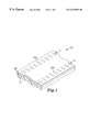
FIG. 1 is a perspective view of a magnetic data storage tape including a plurality of etched servo patterns formed thereon.
FIG. 2 is an enlarged plan view of one etched region of a servo pattern.
FIG. 3 is a cross-sectional view of the etched region of FIG. 2 taken along line 33 in FIG. 2.
FIG. 3A is an enlarged partial cross-sectional view of one etched magnetic data storage tape.
FIG. 4 illustrates one method of providing a servo track on magnetic data storage tape according to the present invention.
FIG. 5 illustrates a method of providing a plurality of servo tracks on magnetic data storage tape according to the present invention.
FIG. 6 illustrates a method of providing servo tracks on two magnetic data storage tapes according to the present invention.
DETAILED DESCRIPTION OF ILLUSTRATIVE EMBODIMENTS OF THE INVENTION
The present invention provides magnetic data storage tape with one or more etched servo patterns formed thereon. FIG. 1 illustrates one magnetic data storage tape 10 according to the present invention. The tape 10 includes a substrate 12 with a magnetic coating 20 on at least one surface of the substrate 12. The substrate 12 may be formed of any suitable material as will be known to those skilled in the art. The magnetic coating 20 may also be any suitable magnetic coating used in magnetic data storage tapes.
Also, it should be understood that although the magnetic coating 20 and substrate 12 are illustrated as homogenous layers, one or both of the magnetic coating 20 and substrate 12 could be provided as composites of multiple layers of the same or different materials. For example, the substrate 12 may include a base layer of, e.g., polyester, coated with non-magnetic materials on one or both sides. Such a composite is considered to be included within the term “substrate” as used in connection with the present invention. Furthermore, multiple magnetic coatings could be provided on the substrate, with at least some of the magnetic coatings being separated by non-magnetic layers. In addition, the substrate could be provided with magnetic coatings on both of its major sides. Other variations in the exact construction of the media used in connection with the present invention will be known to those skilled in the art of magnetic data storage.
The tape 10 includes two servo patterns a, b formed in the magnetic coating 20 on the substrate 12. Each of the servo patterns a, b is formed by a plurality of etched regions 22 a, 22 b (collectively referred to as etched regions 22) that are aligned along the length of the tape 10. The servo patterns a, b are preferably spaced apart across the width of the tape 10, with the area between the servo patterns a, b being used for data storage. Although the servo patterns are illustrated as being etched into the magnetic coating 20, it will be understood that they could alternatively, be formed in the substrate 12.
Also, although the illustrated patterns are one example of a dedicated servo pattern, it will be understood that the present invention could be implemented in any suitable servo system, e.g., embedded servo patterns, etc. Furthermore, although the illustrated pattern is uniformly repeating along the length of the tape, it will be understood that the pattern or patterns formed according to the present invention could vary along the length of the tape and/or transverse to the length of the tape. In addition, the present invention can be used in connection with boundary servo systems or timing based servo systems.
The servo patterns a, b may be read optically, magnetically or both optically and magnetically. If the servo patterns a, b are to be read optically, they may be formed on any appropriate surface of the tape 10. For example, the servo patterns a, b may be formed in a magnetic coating 20 on the tape 10, or they may be formed on another surface, e.g., in the substrate 12. Alternatively, the servo patterns a, b may be formed in another coating provided on the tape 10 that is selected for its ability to provide an optical servo track with enhanced contrast (e.g., a material that provides high contrast). Wherever formed, the servo patterns to be read optically must exhibit sufficient optical modulation when read by an optical read head to provide accurate positioning information.
Servo patterns a, b that are to be read magnetically must be formed in a magnetic coating that is magnetized using a magnetic signal such that the servo patterns can be magnetically read. For example, the servo patterns may be overwritten with a magnetic signal in the form of magnetic tone, a constant magnetic field, etc. If the servo patterns a, b formed in the magnetic coating 20 on the tape 10 are magnetically overwritten, then the servo patterns a, b on the tape 10 and magnetization combine to form servo tracks that provide electromagnetic modulation when read by a magnetic core. The electromagnetic modulation provided by the servo tracks can then be used to provide the desired servo information needed to accurately position the read/write heads during data storage and retrieval.
In those systems in which the servo positioning will be accomplished by a combination of magnetic and optical servo patterns, the same servo pattern may be used to position both magnetically and optically, provided that the servo pattern provides both sufficient electromagnetic and optical modulation. Alternatively, different servo patterns could be used to provide the desired electromagnetic and optical modulation. For example, servo pattern a could be used to provide electromagnetic modulation to a magnetic core while servo pattern b could be used to provide optical modulation. The different patterns could be read simultaneously, sequentially or a combination of simultaneously and sequentially.
The electromagnetic modulation in the servo tracks is caused by the alternating regions 22, in which at least portion of the magnetic coating 20 is removed, and the unaffected magnetic coating 20 between regions 22 along the length of each of the servo patterns a, b. The unaffected magnetic coating 20 retains the magnetization to a greater degree than the etched regions 22 because at least a portion of the magnetic coating 20 in each etched region 22 has been removed, thereby reducing the ability of the tape 10 to retain magnetization by reducing the magnetic moment Alternatively, the etched regions can provide electromagnetic modulation by increasing separation distance between the magnetic core and the magnetic coating as compared to the areas that are not etched.
Although each etched region 22 may be formed as a single etched area, it may be helpful to provide each etched region 22 in the form of a plurality of stitches 24 located within the etched region 22 as illustrated in FIG. 2. If all of the magnetic coating 20 is removed within each of the etched regions 22, the ability to control the height of the read/write head above the tape 10 can be adversely affected. By providing the etched regions 22 as a plurality of spaced apart stitches 24, however, the proper height of the read/write head above the tape 10 may be more easily maintained.
Another variation in the amount of the magnetic coating 20 removed within the etched areas 22 is illustrated in FIG. 3, which is a cross-sectional view of FIG. 2 taken along line 33 in FIG. 2. The additional variable illustrated in FIG. 3 is the depth to which the magnetic coating 20 is removed from the tape 10. As illustrated in FIG. 3, it may be preferred that a portion of the magnetic coating 20 between each stitch 24 and the substrate 12 remain after etching.
FIG. 3A illustrates another alternative tape construction in which substantially all of the magnetic coating 20′ in each stitch 24′ is removed from the tape 10′. The tape 10′ also includes an intermediate layer 14′ between the magnetic coating 20′ and substrate 12′ that can be selected to enhance removal of the magnetic coating 20′. For example, the intermediate layer 14′ may be selected for its optical properties (e.g., reflection, absorption, etc.) when the etching is performed using laser energy.
FIG. 3A also illustrates an etched region 22′ formed in the substrate 12′ on the opposite side of the magnetic coating 20′. The etched region 22′ could be used in connection with an optical servo pattern as discussed above.
Regardless of the actual form of each etched region in the servo patterns, one important function of the etched regions is to reduce the magnetic properties of selected areas on the tape to provide electromagnetic modulation after signal overwriting. That signal modulation should be significant enough to be accurately detected by a magnetic core. As a result, the exact dimensions of and spacing between the etched regions can vary based on a number of factors including, but not limited to: the properties of the magnetic coating on the substrate, the properties of the core on the read heads, etc.
It may be preferred that the etched regions provide enough deformation or destruction in the magnetic coating on the tape such that electromagnetic modulation of at least about 10% or higher in magnetization written over the servo patterns a, b is obtained when read back by a magnetic core. More preferably, the modulation provided by the servo tracks is at least about 25% or higher, and even more preferably the modulation is at least about 50% or higher.
The formation of the etched regions on the magnetic data storage tape is preferably accomplished by providing a magnetic data storage tape including a substantially continuous magnetic coating on a substrate. The tape is then processed to form the etched regions in a pattern that can be read optically or magnetically. The etching is preferably performed by laser ablation, although any suitable technique for selectively removing at least a portion of the magnetic coating can be used in place of or in connection with laser ablation. The etched regions can alternatively be formed by, e.g., contact lithography, chemical etching, etc.
FIG. 4 illustrates one system for providing a servo tracks on magnetic data storage tape. The system includes a source 30 of laser energy that provides a focused beam 32 of laser energy directed at the tape 10. The tape 10 is preferably moved relative to the beam 32 which is modulated to produce the desired servo pattern of spaced-apart etched regions needed to form a servo track on the tape 10. Those skilled in the art of laser ablation processing will understand that some method of debris removal will also be used to control the debris generated by the preferred ablation process. For example, a frozen carbon dioxide cleaning system and/or vacuum may be used to control debris removal.
Also illustrated in FIG. 4 is a magnetic write head 40 used to magnetize at least the area of the servo track or tracks formed on the tape 10. The magnetization may be performed before or after the etching is completed, although it preferably is performed after etching as illustrated in FIG. 4. It will be understood that, although illustrated as being performed in-line with the etching, the magnetization may be accomplished in a separate process that is not performed in-line with etching.
Another variation in the methods of producing an etched magnetic data storage tape 110 is illustrated in FIG. 5. This variation involves the simultaneous formation of a plurality of etched servo track patterns on a tape 110. To do so in, e.g., a process using laser energy to etch the magnetic coating on the tape 110, a plurality of the laser beams 132 a and 132 b may be directed at the tape 110. The beams 132 a and 132 b may come from a single laser in which the output beam is divided, or the beams 132 a and 132 b may come from different lasers.
Yet another variation is illustrated in FIG. 6, in which servo patterns are simultaneously etched into a plurality of magnetic data storage tapes 210 a and 210 b using etching beams 232 a and 232 b. The etching beams 232 a and 232 b may come from a single laser in which the output beam is divided, or the beams 232 a and 232 b may come from different lasers.
Systems and methods for the simultaneous etching of a plurality of servo tracks on one magnetic data storage tape or on a plurality of tapes are described in commonly assigned, copending U.S. patent application Ser. No. 09/251,774, filed on even date herewith.
Although a limited number of illustrative embodiments are described above, various modifications and alterations of this invention will become apparent to those skilled in the art without departing from the scope of this invention, and it should be understood that this invention is not to be unduly limited to the illustrative embodiments and methods set forth herein.

Claims (23)

What is claimed is:
1. A magnetic data storage tape comprising:
a magnetic coating on at least one surface of a substrate;
a plurality of servo tracks, wherein each servo track comprises a plurality of etched regions in the magnetic coating of the tape, the plurality of etched regions being spaced apart along a length of the tape, and wherein the plurality of servo tracks are spaced apart across a width of the tape; and
a magnetic signal written over each servo track, wherein the magnetic signal and each servo track provide electromagnetic modulation to a magnetic core passed over each servo track.
2. A magnetic data storage tape according to claim 1, wherein at least a portion of the magnetic coating in substantially all of each of the plurality of etched regions is removed.
3. A magnetic data storage tape according to claim 1, wherein each etched region of the plurality of etched regions comprises a plurality of stitches in which at least a portion of the magnetic coating is removed.
4. A magnetic data storage tape according to claim 1, wherein the electromagnetic modulation is at least about 10% or higher.
5. A magnetic data storage tape according to claim 1, wherein the electromagnetic modulation is at least about 25% or higher.
6. A magnetic data storage tape according to claim 1, wherein the electromagnetic modulation is at least about 50% or higher.
7. A magnetic data storage tape according to claim 1, further comprising an intermediate layer between the magnetic coating and the substrate, the intermediate layer exhibiting at least one selected optical property.
8. A method of manufacturing magnetic data storage tape comprising:
providing a substrate with a magnetic coating on at least one surface;
etching a plurality of servo tracks in the magnetic coating on the tape, servo pattern comprising a plurality of etched regions, the plurality of etched regions being spaced apart along a length of the tape, wherein the plurality of servo tracks are spaced apart across a width of the tape; and
writing a magnetic signal over each servo track, wherein the magnetic signal and each servo track provide electromagnetic modulation to a magnetic core passed over each servo track.
9. A method according to claim 8, wherein the plurality of servo tracks are formed simultaneously.
10. A method according to claim 8, wherein the plurality of servo tracks are formed sequentially.
11. A method according to claim 8, wherein forming the servo track further comprises removing at least a portion of the magnetic coating in substantially all of each of the plurality of etched regions.
12. A method according to claim 8, wherein forming the servo track further comprises forming a plurality of stitches each of the etched regions, wherein at least a portion of the magnetic coating in each of the stitches is removed.
13. A method according to claim 8, wherein the etching is performed by laser ablation.
14. A method according to claim 8, wherein the electromagnetic modulation is at least about 10% or higher.
15. A method according to claim 8, wherein the electromagnetic modulation is at least about 25% or higher.
16. A method according to claim 8, wherein the electromagnetic modulation is at least about 50% or higher.
17. A method according to claim 8, wherein the magnetic signal is written on the tape after the plurality of servo tracks are formed.
18. A method according to claim 8, wherein the magnetic signal is written on the tape before the plurality of servo tracks are formed.
19. A method of servo positioning on a magnetic data storage tape comprising:
providing a magnetic data storage tape comprising a magnetic coating on at least one surface of a substrate, a servo pattern comprising a plurality of etched regions in the magnetic coating on the tape, the plurality of etched regions being spaced apart along a length of the tape; and a magnetic signal written over the servo pattern;
detecting electromagnetic modulation in the magnetic coating by passing a magnetic core over the servo pattern;
detecting optical modulation by passing an optical read head over the servo pattern; and
positioning a magnetic read/write head based on the electromagnetic modulation and the optical modulation.
20. A method according to claim 19, wherein the electromagnetic modulation and the optical modulation are detected simultaneously.
21. A method according to claim 19, wherein the electromagnetic modulation and the optical modulation are detected sequentially.
22. A method according to claim 19, wherein the electromagnetic modulation and the optical modulation are detected using the same servo pattern.
23. A method according to claim 19, wherein the tape comprises a plurality of servo patterns, and further wherein the electromagnetic modulation and the optical modulation are detected using different servo patterns.
US09/251,648 1999-02-17 1999-02-17 Magnetic data storage tape with etched servo pattern, method of manufacturing same, and method of servo positioning on same Expired - Fee Related US6433951B1 (en)

Priority Applications (4)

Application Number Priority Date Filing Date Title
US09/251,648 US6433951B1 (en) 1999-02-17 1999-02-17 Magnetic data storage tape with etched servo pattern, method of manufacturing same, and method of servo positioning on same
DE10084269T DE10084269T1 (en) 1999-02-17 2000-02-08 Data storage magnetic tape with etched servo track
PCT/US2000/003225 WO2000049607A2 (en) 1999-02-17 2000-02-08 Magnetic data storage tape with etched servo track
JP2000600268A JP2002537623A (en) 1999-02-17 2000-02-08 Magnetic data storage tape with etched servo tracks

Applications Claiming Priority (1)

Application Number Priority Date Filing Date Title
US09/251,648 US6433951B1 (en) 1999-02-17 1999-02-17 Magnetic data storage tape with etched servo pattern, method of manufacturing same, and method of servo positioning on same

Publications (1)

Publication Number Publication Date
US6433951B1 true US6433951B1 (en) 2002-08-13

Family

ID=22952844

Family Applications (1)

Application Number Title Priority Date Filing Date
US09/251,648 Expired - Fee Related US6433951B1 (en) 1999-02-17 1999-02-17 Magnetic data storage tape with etched servo pattern, method of manufacturing same, and method of servo positioning on same

Country Status (4)

Country Link
US (1) US6433951B1 (en)
JP (1) JP2002537623A (en)
DE (1) DE10084269T1 (en)
WO (1) WO2000049607A2 (en)

Cited By (22)

* Cited by examiner, † Cited by third party
Publication number Priority date Publication date Assignee Title
US20020167751A1 (en) * 1999-07-27 2002-11-14 Tzuochang Lee Optical servo track identification on tape storage media
US6493174B1 (en) * 2000-02-17 2002-12-10 Imation Corp. Optical servo system for use with magnetic data storage tape having magnetic reference indicators
US20030035238A1 (en) * 2001-08-20 2003-02-20 George Bellesis Optical to magnetic alignment in magnetic tape system
US20030043498A1 (en) * 2001-09-05 2003-03-06 Robert Johnson Magnetic servo of a recording head
US6606220B1 (en) * 1999-06-11 2003-08-12 Quantum Corporation Systems and methods for providing beginning-of-tape and end-of-tape indicators
US6741415B1 (en) * 1999-02-16 2004-05-25 Quantum Corporation Method of writing servo signal on magnetic tape
US20040100719A1 (en) * 2002-11-22 2004-05-27 Seagate Technology Llc Writing multiple servo sector patterns to improve servo sector alignment on multiple surfaces
EP1445763A1 (en) * 2003-02-05 2004-08-11 Quantum Corporation Magnetic media with embedded optical servo tracks
US20050083601A1 (en) * 2003-10-20 2005-04-21 Faramarz Mahnad Servo methods and systems using existing data structures and optical masks
US20050083600A1 (en) * 2003-10-20 2005-04-21 Faramarz Mahnad Methods and systems for magnetic recording
US20050083602A1 (en) * 2003-10-20 2005-04-21 Saliba George A. Servo methods and systems using existing data structures and medium edge position
US20050088770A1 (en) * 2003-10-20 2005-04-28 George A. Saliba Electromagnetic void-sensing probes and position control systems
US20050094308A1 (en) * 2003-10-20 2005-05-05 Faramarz Mahnad Servo methods and systems using masked medium edge position sensors
US6940676B1 (en) * 2000-06-07 2005-09-06 Quantum Corporation Triple push-pull optical tracking system
US20050270687A1 (en) * 2004-06-04 2005-12-08 James Zweighaft Dual source tracking servo systems and associated methods
US20060082916A1 (en) * 2004-10-14 2006-04-20 Evans Nigel R Tape drive apparatus
US20060209450A1 (en) * 2005-03-18 2006-09-21 Quantum Corporation Auto-servo tape system and associated recording head
US20060262441A1 (en) * 2005-05-19 2006-11-23 Quantum Corporation Write protected magnetic storage media and associated methods
US7149050B2 (en) 2003-10-20 2006-12-12 Quantum Corporation Diffractive position sensors and control systems
US20070097536A1 (en) * 2005-10-27 2007-05-03 Biskeborn Robert G Asperity data storage system, method and medium
US20070097534A1 (en) * 2005-10-28 2007-05-03 Evans Nigel R Tape drive apparatus and method
US20080266705A1 (en) * 2007-04-25 2008-10-30 Quantum Corporation Servo error detection and compensation utilizing virtual data tracking servo methods

Citations (18)

* Cited by examiner, † Cited by third party
Publication number Priority date Publication date Assignee Title
US4315283A (en) 1976-04-08 1982-02-09 Victor Company Of Japan, Ltd. High density recording system using side-by-side information and servo tracks
JPS6070543A (en) 1983-09-28 1985-04-22 Toshiba Corp Information recording carrier
US4645722A (en) 1983-09-22 1987-02-24 Director-General Of Agency Of Industrial Science & Technology Photo-thermo-magnetic recording medium and method of preparing same
JPS6442044A (en) 1987-08-10 1989-02-14 Nec Corp Optical recording medium
US4816939A (en) * 1986-08-21 1989-03-28 Polaroid Corporation Magnetic recording media and servo systems using light-transmitting optical gratings
US4843494A (en) * 1987-10-15 1989-06-27 Polaroid Corporation Data storage apparatus using optical servo tracks
US4961123A (en) * 1988-06-03 1990-10-02 Insite Peripherals Magnetic information media storage with optical servo tracks
JPH03201215A (en) 1989-12-27 1991-09-03 Tdk Corp Magnetic recording medium and method of magnetic recording and reproducing
US5067039A (en) 1989-10-20 1991-11-19 Insite Peripherals, Inc. High track density magnetic media with pitted optical servo tracks and method for stamping the tracks on the media
US5089358A (en) 1988-11-05 1992-02-18 Brother Kogyo Kabushiki Kaisha Optical recording medium
US5279775A (en) 1992-06-10 1994-01-18 Iomega Corporation Acousto-optical intensity control of laser beam during etching of optical servo information of magnetic media
US5283773A (en) 1992-06-10 1994-02-01 Iomega Corporation Steering laser beam while etching optical servo tracks for magnetic disks
US5462823A (en) * 1992-11-16 1995-10-31 Minnesota Mining And Manufacturing Company Magnetic recording materials provided with a photosensitive layer
US5619480A (en) 1992-11-06 1997-04-08 Mitsubishi Chemical Corporation Magnetic recording medium and recording/reproducing method therefor as well as information processing apparatus by means thereof
US5674583A (en) 1989-11-22 1997-10-07 Sharp Kabushiki Kaisha Optical recording medium and manufacturing method thereof
US5689384A (en) 1994-06-30 1997-11-18 International Business Machines Corporation Timing based servo system for magnetic tape systems
US5952074A (en) * 1994-08-03 1999-09-14 Hitachi Maxell, Ltd. Magnetic recording medium
US6018434A (en) * 1997-01-14 2000-01-25 Quantum Corporation Tape cartridge having written-in-defect servo patterns for rapid head position calibration

Patent Citations (18)

* Cited by examiner, † Cited by third party
Publication number Priority date Publication date Assignee Title
US4315283A (en) 1976-04-08 1982-02-09 Victor Company Of Japan, Ltd. High density recording system using side-by-side information and servo tracks
US4645722A (en) 1983-09-22 1987-02-24 Director-General Of Agency Of Industrial Science & Technology Photo-thermo-magnetic recording medium and method of preparing same
JPS6070543A (en) 1983-09-28 1985-04-22 Toshiba Corp Information recording carrier
US4816939A (en) * 1986-08-21 1989-03-28 Polaroid Corporation Magnetic recording media and servo systems using light-transmitting optical gratings
JPS6442044A (en) 1987-08-10 1989-02-14 Nec Corp Optical recording medium
US4843494A (en) * 1987-10-15 1989-06-27 Polaroid Corporation Data storage apparatus using optical servo tracks
US4961123A (en) * 1988-06-03 1990-10-02 Insite Peripherals Magnetic information media storage with optical servo tracks
US5089358A (en) 1988-11-05 1992-02-18 Brother Kogyo Kabushiki Kaisha Optical recording medium
US5067039A (en) 1989-10-20 1991-11-19 Insite Peripherals, Inc. High track density magnetic media with pitted optical servo tracks and method for stamping the tracks on the media
US5674583A (en) 1989-11-22 1997-10-07 Sharp Kabushiki Kaisha Optical recording medium and manufacturing method thereof
JPH03201215A (en) 1989-12-27 1991-09-03 Tdk Corp Magnetic recording medium and method of magnetic recording and reproducing
US5279775A (en) 1992-06-10 1994-01-18 Iomega Corporation Acousto-optical intensity control of laser beam during etching of optical servo information of magnetic media
US5283773A (en) 1992-06-10 1994-02-01 Iomega Corporation Steering laser beam while etching optical servo tracks for magnetic disks
US5619480A (en) 1992-11-06 1997-04-08 Mitsubishi Chemical Corporation Magnetic recording medium and recording/reproducing method therefor as well as information processing apparatus by means thereof
US5462823A (en) * 1992-11-16 1995-10-31 Minnesota Mining And Manufacturing Company Magnetic recording materials provided with a photosensitive layer
US5689384A (en) 1994-06-30 1997-11-18 International Business Machines Corporation Timing based servo system for magnetic tape systems
US5952074A (en) * 1994-08-03 1999-09-14 Hitachi Maxell, Ltd. Magnetic recording medium
US6018434A (en) * 1997-01-14 2000-01-25 Quantum Corporation Tape cartridge having written-in-defect servo patterns for rapid head position calibration

Non-Patent Citations (1)

* Cited by examiner, † Cited by third party
Title
"Timing-Based Track-Following Servo for Linear Tape Systems," Barrett et al., IEEE Transactions on Magnetics, vol. 34, No. 4, Jul. 1998, pp. 1872-1877.

Cited By (41)

* Cited by examiner, † Cited by third party
Publication number Priority date Publication date Assignee Title
US6741415B1 (en) * 1999-02-16 2004-05-25 Quantum Corporation Method of writing servo signal on magnetic tape
US6606220B1 (en) * 1999-06-11 2003-08-12 Quantum Corporation Systems and methods for providing beginning-of-tape and end-of-tape indicators
US20020167751A1 (en) * 1999-07-27 2002-11-14 Tzuochang Lee Optical servo track identification on tape storage media
US6961200B2 (en) * 1999-07-27 2005-11-01 Quantum Corporation Optical servo track identification on tape storage media
US6493174B1 (en) * 2000-02-17 2002-12-10 Imation Corp. Optical servo system for use with magnetic data storage tape having magnetic reference indicators
US6940676B1 (en) * 2000-06-07 2005-09-06 Quantum Corporation Triple push-pull optical tracking system
US20030035238A1 (en) * 2001-08-20 2003-02-20 George Bellesis Optical to magnetic alignment in magnetic tape system
US6940681B2 (en) * 2001-08-20 2005-09-06 Quantum Corporation Optical to magnetic alignment in magnetic tape system
US20030043498A1 (en) * 2001-09-05 2003-03-06 Robert Johnson Magnetic servo of a recording head
US6856484B2 (en) * 2001-09-05 2005-02-15 Quantum Corporation Magnetic servo of a recording head
US20040100719A1 (en) * 2002-11-22 2004-05-27 Seagate Technology Llc Writing multiple servo sector patterns to improve servo sector alignment on multiple surfaces
US7511912B2 (en) * 2002-11-22 2009-03-31 Seagate Technology Llc Writing multiple servo sector patterns to improve servo sector alignment on multiple surfaces
EP1445763A1 (en) * 2003-02-05 2004-08-11 Quantum Corporation Magnetic media with embedded optical servo tracks
US7102845B2 (en) * 2003-10-20 2006-09-05 Quantum Corporation Servo methods and systems using existing data structures and medium edge position
US7149050B2 (en) 2003-10-20 2006-12-12 Quantum Corporation Diffractive position sensors and control systems
US20050088770A1 (en) * 2003-10-20 2005-04-28 George A. Saliba Electromagnetic void-sensing probes and position control systems
US20050083602A1 (en) * 2003-10-20 2005-04-21 Saliba George A. Servo methods and systems using existing data structures and medium edge position
US20050083601A1 (en) * 2003-10-20 2005-04-21 Faramarz Mahnad Servo methods and systems using existing data structures and optical masks
US20050094308A1 (en) * 2003-10-20 2005-05-05 Faramarz Mahnad Servo methods and systems using masked medium edge position sensors
US7085095B2 (en) 2003-10-20 2006-08-01 Quantum Corporation Electromagnetic void-sensing probes and position control systems
US20050083600A1 (en) * 2003-10-20 2005-04-21 Faramarz Mahnad Methods and systems for magnetic recording
US7139152B2 (en) * 2003-10-20 2006-11-21 Quantum Corporation Servo methods and systems using existing data structures and optical masks
US7116514B2 (en) 2003-10-20 2006-10-03 Quantum Corporation Methods and systems for magnetic recording
US7136255B2 (en) * 2003-10-20 2006-11-14 Quantum Corporation Servo methods and systems using masked medium edge position sensors
US7184233B2 (en) 2004-06-04 2007-02-27 Quantum Corporation Dual source tracking servo systems and associated methods
US20050270687A1 (en) * 2004-06-04 2005-12-08 James Zweighaft Dual source tracking servo systems and associated methods
US20060082916A1 (en) * 2004-10-14 2006-04-20 Evans Nigel R Tape drive apparatus
US20060209450A1 (en) * 2005-03-18 2006-09-21 Quantum Corporation Auto-servo tape system and associated recording head
US7649707B2 (en) 2005-03-18 2010-01-19 Quantum Corporation Auto-servo tape system and associated recording head
US7499235B2 (en) 2005-03-18 2009-03-03 Quantum Corporation Auto-servo tape system and associated recording head
US7414803B2 (en) * 2005-05-19 2008-08-19 Quantum Corporation Write protected magnetic storage media and associated methods
US20060262441A1 (en) * 2005-05-19 2006-11-23 Quantum Corporation Write protected magnetic storage media and associated methods
US20070097536A1 (en) * 2005-10-27 2007-05-03 Biskeborn Robert G Asperity data storage system, method and medium
US20080259483A1 (en) * 2005-10-27 2008-10-23 International Business Machines Corporation Asperity data storage system, method and medium
US20070242382A1 (en) * 2005-10-27 2007-10-18 International Business Machines Corporation Asperity data storage system, method and medium
US7508612B2 (en) 2005-10-27 2009-03-24 International Business Machines Corporation Asperity data storage system, method and medium
US7265922B2 (en) * 2005-10-27 2007-09-04 International Business Machines Corporation Asperity data storage system, method and medium
US20070097534A1 (en) * 2005-10-28 2007-05-03 Evans Nigel R Tape drive apparatus and method
US8576505B2 (en) 2005-10-28 2013-11-05 Hewlett-Packard Development Company, L.P. Tape drive apparatus and method
US20080266705A1 (en) * 2007-04-25 2008-10-30 Quantum Corporation Servo error detection and compensation utilizing virtual data tracking servo methods
US7826169B2 (en) 2007-04-25 2010-11-02 Quantum Corporation Servo error detection and compensation utilizing virtual data tracking servo methods

Also Published As

Publication number Publication date
DE10084269T1 (en) 2002-03-28
WO2000049607A2 (en) 2000-08-24
WO2000049607A3 (en) 2000-12-14
JP2002537623A (en) 2002-11-05

Similar Documents

Publication Publication Date Title
US6433951B1 (en) Magnetic data storage tape with etched servo pattern, method of manufacturing same, and method of servo positioning on same
US6703099B2 (en) Perpendicular magnetic recording media with patterned soft magnetic underlayer
US20070211380A1 (en) Perpendicular magnetic head
US7061703B2 (en) Master information carrier and method for manufacturing magnetic disc using the same
JPH08185676A (en) Magnetic disk and disk device
EP0533178B1 (en) Hard disc drive
JP2001312819A (en) Method for magnetic recording on perpendicular magnetic recording medium by using master information carrier
US6999269B2 (en) Two-sided data storage tape with servo information on both sides of the tape
CA2081153C (en) Magneto-optical memory device whereon overwriting operation can be carried out through light intensity modulation and method for recording and erasing using it
US5323366A (en) Magneto-optical recording method with switching and maintaining perpendicular magnetization light beam application modes
Gomez et al. Microscopic investigations of overwritten data
EP0444833B1 (en) Magnetic recording apparatus and magnetic recording method
US6950278B2 (en) Magnetic head
JP2883101B2 (en) Information recording device
JP2586521B2 (en) Magnetic recording medium and method of manufacturing the same
JP2714085B2 (en) Information recording method
JP2009037700A (en) Magnetic recording medium
JPS5835713A (en) Magnetic head for vertical magnetization recording
JPH0786982B2 (en) Optical memory device
JPH097143A (en) Magnetic disk and tracking method
JPS61237231A (en) Magnetic recording body and its production
JP2002203315A (en) Magnetic recording method
JPS59142719A (en) Thin-film head
JPS5972643A (en) Magnetic recording medium
JPH0766509B2 (en) Magnetic recording body and manufacturing method thereof

Legal Events

Date Code Title Description
AS Assignment

Owner name: IMATION CORP., MINNESOTA

Free format text: ASSIGNMENT OF ASSIGNORS INTEREST;ASSIGNOR:LUBRATT, MARK P.;REEL/FRAME:009929/0471

Effective date: 19990416

AS Assignment

Owner name: IMATION CORP., MINNESOTA

Free format text: ASSIGNMENT OF ASSIGNORS INTEREST;ASSIGNORS:LUBRATT, MARK P.;MARTIN, ROBERT C.;MOLSTAD, RICHARD W.;REEL/FRAME:010294/0282

Effective date: 19990924

CC Certificate of correction
FPAY Fee payment

Year of fee payment: 4

REMI Maintenance fee reminder mailed
LAPS Lapse for failure to pay maintenance fees
STCH Information on status: patent discontinuation

Free format text: PATENT EXPIRED DUE TO NONPAYMENT OF MAINTENANCE FEES UNDER 37 CFR 1.362

FP Lapsed due to failure to pay maintenance fee

Effective date: 20100813