US6477154B1 - Microcellular mobile communication system - Google Patents
Microcellular mobile communication system Download PDFInfo
- Publication number
- US6477154B1 US6477154B1 US09/138,470 US13847098A US6477154B1 US 6477154 B1 US6477154 B1 US 6477154B1 US 13847098 A US13847098 A US 13847098A US 6477154 B1 US6477154 B1 US 6477154B1
- Authority
- US
- United States
- Prior art keywords
- signals
- hfr
- reverse link
- forward link
- micro base
- Prior art date
- Legal status (The legal status is an assumption and is not a legal conclusion. Google has not performed a legal analysis and makes no representation as to the accuracy of the status listed.)
- Expired - Lifetime
Links
Images


Classifications
-
- H—ELECTRICITY
- H04—ELECTRIC COMMUNICATION TECHNIQUE
- H04W—WIRELESS COMMUNICATION NETWORKS
- H04W16/00—Network planning, e.g. coverage or traffic planning tools; Network deployment, e.g. resource partitioning or cells structures
- H04W16/24—Cell structures
- H04W16/32—Hierarchical cell structures
-
- H—ELECTRICITY
- H04—ELECTRIC COMMUNICATION TECHNIQUE
- H04B—TRANSMISSION
- H04B7/00—Radio transmission systems, i.e. using radiation field
- H04B7/24—Radio transmission systems, i.e. using radiation field for communication between two or more posts
- H04B7/26—Radio transmission systems, i.e. using radiation field for communication between two or more posts at least one of which is mobile
-
- H—ELECTRICITY
- H04—ELECTRIC COMMUNICATION TECHNIQUE
- H04B—TRANSMISSION
- H04B10/00—Transmission systems employing electromagnetic waves other than radio-waves, e.g. infrared, visible or ultraviolet light, or employing corpuscular radiation, e.g. quantum communication
- H04B10/25—Arrangements specific to fibre transmission
- H04B10/2575—Radio-over-fibre, e.g. radio frequency signal modulated onto an optical carrier
- H04B10/25752—Optical arrangements for wireless networks
- H04B10/25753—Distribution optical network, e.g. between a base station and a plurality of remote units
-
- H—ELECTRICITY
- H04—ELECTRIC COMMUNICATION TECHNIQUE
- H04J—MULTIPLEX COMMUNICATION
- H04J3/00—Time-division multiplex systems
- H04J3/02—Details
- H04J3/06—Synchronising arrangements
- H04J3/0635—Clock or time synchronisation in a network
- H04J3/0638—Clock or time synchronisation among nodes; Internode synchronisation
-
- H—ELECTRICITY
- H04—ELECTRIC COMMUNICATION TECHNIQUE
- H04J—MULTIPLEX COMMUNICATION
- H04J3/00—Time-division multiplex systems
- H04J3/02—Details
- H04J3/06—Synchronising arrangements
- H04J3/0635—Clock or time synchronisation in a network
- H04J3/0682—Clock or time synchronisation in a network by delay compensation, e.g. by compensation of propagation delay or variations thereof, by ranging
-
- H—ELECTRICITY
- H04—ELECTRIC COMMUNICATION TECHNIQUE
- H04W—WIRELESS COMMUNICATION NETWORKS
- H04W88/00—Devices specially adapted for wireless communication networks, e.g. terminals, base stations or access point devices
- H04W88/08—Access point devices
- H04W88/085—Access point devices with remote components
-
- Y—GENERAL TAGGING OF NEW TECHNOLOGICAL DEVELOPMENTS; GENERAL TAGGING OF CROSS-SECTIONAL TECHNOLOGIES SPANNING OVER SEVERAL SECTIONS OF THE IPC; TECHNICAL SUBJECTS COVERED BY FORMER USPC CROSS-REFERENCE ART COLLECTIONS [XRACs] AND DIGESTS
- Y02—TECHNOLOGIES OR APPLICATIONS FOR MITIGATION OR ADAPTATION AGAINST CLIMATE CHANGE
- Y02D—CLIMATE CHANGE MITIGATION TECHNOLOGIES IN INFORMATION AND COMMUNICATION TECHNOLOGIES [ICT], I.E. INFORMATION AND COMMUNICATION TECHNOLOGIES AIMING AT THE REDUCTION OF THEIR OWN ENERGY USE
- Y02D30/00—Reducing energy consumption in communication networks
- Y02D30/70—Reducing energy consumption in communication networks in wireless communication networks
Definitions
- the present invention relates to a microcellular mobile communication system using a Code Division Multiple Access (CDMA) scheme, more particularly the microcellular mobile communication system that provides subscribers with the high-speed mobile communication service more stably by providing the mobile communication service based on a microcell of a radius of several hundred meters, and improves frequency utility efficiency.
- CDMA Code Division Multiple Access
- the microcellular mobile communication system may extend the life span of a mobile station because a cell radius is small, and is interesting as a structure to which a variety of services (i.e. data and image) are applicable.
- This microcellular mobile communication system needs a large number of base stations, which will increase the cost of initial facility investment and maintenance.
- a Base Station Transceiver System (BTS) in the conventional CDMA cellular mobile communication system, is connected with other equipments through E1/T1 or high-speed digital subscriber lines.
- the BTS comprises a digital unit including the CDMA Channel Element Assembly (CCEA) for modulating and demodulating the signal of the CDMA scheme, a control processor including a Radio Frequency (RF) signal processing unit, a Base Station Controller (BSC) interface and an operation management interface, and the Global Positioning System (GPS) for synchronization between base stations and so on.
- CCEA CDMA Channel Element Assembly
- RF Radio Frequency
- BSC Base Station Controller
- GPS Global Positioning System
- Such a BTS is not appropriate for a mobile communication system composed of a microcell type when taking weight or volume into account.
- there is an outdoor BTS of a small capacity structure but it is difficult to install the BTS appropriate for various RF environments of metropolitan, in which it is needed, every several hundred meters and to extend capacity.
- an antenna technique using the optical or the separate antenna has been used.
- this technique which transmits only an RF signal from the conventional BTS to a remote antenna through a coaxial cable or an optical fiber, is not appropriate for the mobile communication system of a large scale of microcell type in the future due to a synchronous problem between the conventional BTS and its antenna. That is, these can not perform various functions, needed for the microcell environment, which extend new cells, in order to increase the subscriber capacity, manage resources while maintaining the conventional service, or process a softer handover in more than three cells.
- an object of the present invention is to provide a microcelluar mobile communication system that can perform various functions such as a centralized management of resources, a capacity increase, a Base Station Transceiver System (BTS) miniaturization, a synchronization between micro base stations, a dynamic resource management, a softer handover between cells, a grouping and ungrouping of base stations in accordance with a traffic distribution.
- BTS Base Station Transceiver System
- the present invention comprises a GPS receiver for generating a timing information and a reference clock signal to maintain synchronization of a system and a network; a micro base station controller for interfacing with a base station controller, performing a spreading modulation and demodulation, combining signals through a switching operation for dynamic channel allocation between cells and softer handover process, and up-converting the combined signal into at intermediate frequency so that said micro base station controller outputs the up-converted signal with a cable frequency if said micro base station controller transmits a signal to a plurality of micro base stations, and conversely down-converting a received cable frequency into the intermediate frequency so that said micro base station controller transmits a packetized message to said base station controller if said micro base station controller receives a signal from said plurality of micro base stations; a transferring means connected between said GPS receiver and said micro base station controller, for transferring the cable frequency signal in respond to a control signal; and said plurality of micro base stations for transmitting and receiving the cable frequency signal to and from said micro base station controller
- the present invention is divided into a digital hardware and an RF transceiver, the digital hardware and the RF transceiver are connected through optical fibers or hybrid fiber coaxial networks based on the Subcarrier Multiplexing (SCM) technique.
- SCM means a transmission scheme that carries information on different frequencies from each other electrically in the transmission stage, combines the carried information, electrical-to-optical converts and transmits it through optical fibers, and optical-to-electrical converts and then recovers to an original signal through a band pass filtering.
- the microcellular mobile communication of the present invention comprises a micro Base Station Controller (mBSC), which may manage resources in the center and supports a plurality of microcells, a Hybrid Fiber Radio (HFR) network based on the SCM technique and a plurality of micro Base Stations (mBSs) connected to the mBSC.
- mBSC micro Base Station Controller
- HFR Hybrid Fiber Radio
- mBSs micro Base Stations
- the HFR as a hybrid technique of the broad band nature of wire (optical fiber) and the mobility of radio, means that it transmits a Radio Frequency (RF) or an Intermediate Frequency (IF) through the optical fiber.
- RF Radio Frequency
- IF Intermediate Frequency
- the micro Base Station (mBS) proposed in this invention is installed within each microcell as an equipment only having an HFR network module, a simple control signal processor, a frequency up/down converter, an amplifier, a filter, a power source and so on.
- the mBSs are connected with the MBSC through the optical fiber or the hybrid fiber coaxial network.
- the MBSC performing the centralized control of the mBS comprises the digital hardware of the conventional Base Station Transceiver System (BTS), a Code Stream Switch (CSS) being capable of a dynamic resource allocation and the softer handover, an HFR network management module, the HFR network interface module and so on.
- BTS Base Station Transceiver System
- CSS Code Stream Switch
- the mBSC performs the centralized-management of the mBS through the CSS, and minimizes an initial investment cost for constructing a microcell mobile communication system by allocating dynamically an intercell communication channel, and allows a cell design satisfying an optimum capacity. That is, the present invention as compared with the distributed control network of the conventional base station, permits the centralized control network, the dynamic channel allocation, and the base station grouping operation, and may process a handover between base stations with the softer handover.
- the mBSC converts a signal to be transmitted to each mBS into a cable frequency signal and then transmits the cable frequency signal through the HFR network.
- the mBS receives the cable frequency signal and then transmits the RF through an antenna after up-converting the cable frequency signal into the RF for personal communications system.
- the RF received from a mobile station is received in the mBS and then transmitted to the mBSC through a reverse link.
- the present invention installs a GPS receiver in the mBSC without installing additionally the GPS receiver in the mBS, transmits a reference clock signal from the GPS receiver through the HFR network, and maintains the synchronization between mBSs.
- the mBS installation cost is reduced, and the cell design may be applied to an indoor, a tunnel and so on that it is difficult for a GPS antenna to be installed.
- the communication system and network in accordance with the present invention interface with other communication network and are designed so that various radio communication services may be accommodated.
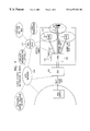
- FIG. 1 shows schematically an overall construction of a microcellular mobile system for a personal communication according to the present invention.
- FIG. 2 shows a connection structure between an mBSC and an for explaining an operation of a forward link function according to the present invention.
- FIGS. 3A and 3B show an exemplary embodiment applying offset to pilot PN code according to the present invention.
- FIG. 4 is a block diagram of an mBS transmitter according to the present invention.
- FIG. 5A shows a distribution of a forward cable frequency.
- FIG. 5B shows an exemplary embodiment of a method of allocating a forward cable frequency.
- FIG. 6 shows a connection structure between an mBSC and an mBS for explaining an operation of a reverse link function according to the present invention.
- FIG. 7 is a block diagram of an mBS receiver according to the present invention.
- FIG. 8A shows a distribution of a reverse cable frequency.
- FIG. 8B shows an exemplary embodiment of a method of allocating a reverse cable frequency.
- FIG. 9 is a block diagram of an MBSC according to the present invention.
- FIG. 10 shows a detailed construction of a switching module within a code stream switch according to the present invention.
- FIG. 1 shows schematically an overall construction of a microcellular mobile system for a personal communication according to the present invention.
- the micro Base Station (mBS) 102 comprises a radio frequency (RF) front end, an HFR network interface module and so on which were comprised in the conventional Base Station Transceiver System (BTS).
- the micro Base Station Controller (mBSC) 101 comprises a part corresponding to a digital module, a control part and so on so that the present invention can perform a centralized control management and a dynamic channel allocation.
- the mBSC 101 and the mBS 102 are connected through the HFR network 103 .
- a forward link refers to a direction from the mBSC 101 to the mBS 102 and a reverse link does a direction from the mBS 102 to the mBSC 101 .
- a signal to be transmitted through the HFR network 103 is the signal using a Subcarrier Multiplexing (SCM) scheme and a Wavelength Division Multiplexing (WDM) scheme.
- the mBSC 101 is connected with the conventional base station controller through a digital connection of E1/T1, HDSL and so on and a signal connection of an interprocessor communication.
- a high-level communication network becomes developed into other network, for example, the Asynchronous Transfer Mode (ATM) network 106
- ATM Asynchronous Transfer Mode
- the present invention's mBSC 101 can be connected with the ATM network 106 by only changing the high-level communication network interface module of the mBSC 101 .
- the HFR network 103 and the mBS 102 as well as the mBSC 101 may be applied to the intelligent network and the ATM network.
- the synchronization between the mBSs 102 is adjusted through the GPS receiver 104 connected to the mBSC 101 , and a reference clock signal is transmitted to the mBS 102 in order to adjust the synchronization between the mBSs 102 .
- the HFR network 103 connected with the HFR network node 107 through the optical fiber may be developed into a form of the public switched telephone network and utilized as an access network of various services such as the wireless/wire cable television and so on.
- the microcellular mobile communication system in accordance with the present invention may support efficiently the personal communications service (PCS) of the CDMA scheme, and may adapt superiorly to the development of the high-level communication network, and has a structure that it may support various radio communication services with a form of the HFR public switched telephone network in the future.
- PCS personal communications service
- the present invention is not limited to the personal communications service.
- FIG. 2 shows a connection structure between the mBSC and the mBS for explaining an operation of a forward link function according to the present invention.
- the Personal Communications Service (PCS) module 201 within the mBSC performs a function corresponding to the digital unit of the conventional Base Station Transceiver System (BTS).
- BTS Base Station Transceiver System
- the BTS Control Processor (BCP) 206 comprises a module for interfacing with the conventional base station controller.
- the BCP 206 controls the Channel Interface Processor (CIP) 205
- the CIP 205 controls the CDMA Channel Element Assembly (CCEA) 202 and the Code Stream Switch (CSS) 203 .
- CIP Channel Interface Processor
- CEA CDMA Channel Element Assembly
- CSS Code Stream Switch
- the BCP 206 further includes a function for communication with the CIP 205 and a function for interfacing with the HFR network controller 208 in order to control the CSS 203 .
- the CIP 205 further includes the CSS controlling function for a dynamic resource management and a softer handover between cells.
- the CCEA 202 as the prior art performs spread modulation/demodulation functions according to the CDMA scheme.
- each channel of the CCEA 202 outputs I, Q signals by ⁇ , ⁇ , ⁇ sectors to the CSS 203 .
- the CSS 203 performs a function for mapping a three-sector structure to a plurality of microcells, as a structure proposed in the present invention, so that the dynamic channel allocation and the softer handover between cells can be made.
- the CSS 203 switches appropriately signals received from the CCEA 202 according to the control of the CIP 205 and then combines digital signals received by each of microcells. Such signals are up-converted into the CDMA IF 4.95 MHz through QPSK modulation in the CDMA IF Transmission Assembly (CITA) 204 .
- CITA CDMA IF Transmission Assembly
- the Transceiver block (XCVB) 207 means a network interface module signal, and its function is to convert the output signal of each CITA 204 into a cable frequency by microcells.
- the cable frequency combiner 211 combines the output signals of the XCVB 207 , a forward control signal for the HFR network management such as the mBSs 216 , 221 and 225 maintenance/management and so on, and a reference clock signal in the frequency domain. Such combined electrical signals are converted into the optical frequency ⁇ 1 through the electrical-to-optical converter (E/O). That is, they are transmitted by the SCM scheme.
- E/O electrical-to-optical converter
- the optical node or optical splitter 214 may be interfaced with HFC network.
- the reference numeral 214 refers to an optical splitter
- the reference numeral 215 refers to a structure of star-shaped optical fiber network
- the reference numeral 214 refers to optical node
- the reference numeral 215 refers to a structure of coaxial network. Consequently, the micro base station 216 up-converts a message conveyed on the cable frequency transmitted from the XCVB 207 , into the RF, and transmits the up-converted message to a mobile station.
- the HFR network controller 208 controls the operation/management of HFR network including the mBS, the grouping/ungrouping of the mBSs, a power source, a plurality of Frequency Allocation (FA) transmissions, the RF change and so on, wherein the HFR network controller 208 controls each mBS by a polling scheme and transmits a forward control channel signal to each mBS, after generating it through the control signal generator 209 .
- FFA Frequency Allocation
- the HFR network controller 208 is connected to a HFR network management system (NMS).
- NMS HFR network management system
- the GPS receiver 212 as the prior art, generates reference clock signals and timing information necessary to each module to maintain the system and network synchronization.
- the reference clock signals are transmitted to each mBS through the cable frequency combiner 211 , comprising the GPS receiver 212 to mBS, without installing the GPS receiver every mBS for synchronization between mBSs.
- the reference clock signals (for example, 10 MHz) generated from the GPS receiver 212 of mBSC, are transmitted to the mBS through the HFR network for the frequency coherence between mBSs.
- the microcellular mobile communication system in the accordance with present invention as described above may be connected with the Wireless Local Loop (WLL) service module 217 for providing a WLL service, and the service module 222 for providing the third generation mobile communication service. That is, the WLL service module 217 up-converts the RF into the cable frequency appropriate to a service and then provides the channel frequency combiner 211 of the present invention with the signals converted by the additional IF converter 218 , or converts electrical signals into optical signals using the additional electrical-to-optical converter 219 , and then provides the optical splitter or optical node 214 with the converted signals through the optical wavelength coupler (not shown) included in the path 220 .
- WLL Wireless Local Loop
- the third generation mobile communication service module 222 up-converts the RF into the cable frequency appropriate to a service and then provides the channel frequency combiner 211 of the present invention with the signals converted by the additional IF converter 223 , or provides the optical wavelength coupler of the path 220 with the RF through the additional electrical-to-optical converter 224 .
- the optical splitter or optical node 214 is connected to the mBSs 221 and 225 for providing these services.
- a wavelength Division Multiplexing (WDM) scheme may be applicable to a service since a broad band spectrum is possible.
- the electrical-to-optical converters 219 and 224 have different wavelengths ⁇ 2 and ⁇ 3 from the electrical-to-optical converter 213 and the wavelengths ⁇ 2 and ⁇ 3 may be transmitted to each mBS through the optical wavelength coupler of the path 220 .
- the wavelengths ⁇ 2 and ⁇ 3 are selected in the mBSs 221 and 225 , respectively as appropriate to the demand according to optical wavelength and then transmitted by the desired radio frequency band.
- the present invention applies for each cell offset values of Pseudo Noise (PN) codes of different pilot channels, and then classifies each cell. For that, at the installation time the microcellular mobile communication system measures or calculates the transfer delay time of signal between the mBSC and the mBS, and applies a store and forward scheme in the mBSC depending upon this transfer delay time, so that the mBSC transmits a pilot message to the mBS while adjusting a timing to each mBS. This procedure is illustrated in FIGS. 3A and 3B in detail.
- PN Pseudo Noise
- FIGS. 3A and 3B show an exemplary embodiment applying offset to pilot PN code according to the present invention.
- An mBSC module applies an offset value to a delay time value taking the delay time from the mBSC to antennas of every mBS into account. That is, when the mBSC module measures the transfer delay time of HFR network to each mBS using an Optical Time Domain Reflectometer (OTDR) 226 as shown in FIGS. 3A, and finds the transfer delay time of the mBS itself to set a storage time on the basis of GPS time (even second) 227 (FIG. 3 B), a message is transmitted from the antenna of each mBS according to pilot pseudo noise code (Point-PN) 228 (FIG. 3 B). Such a timing adjustment may be implemented in the CCEA or the CITA within the mBSC.
- OTDR Optical Time Domain Reflectometer
- FIG. 4 is a block diagram of an mBS transmitter according to the present invention.
- the optical signals transmitted through the optical fiber link 301 are converted into the electrical signals of cable frequency by the optical-to-electrical converter 302 .
- the signals are converted into radio frequency band by the variable up-converter 305 .
- Reference clock signals (for example, 10 MHz) are provided to the variable up-converter 305 after being filtered by the Phase Locked Loop (PLL) filter 308 and used as reference frequency for up-converting electrical signals.
- PLL Phase Locked Loop
- Forward control channel signals are decoded in the control signal processor 309 and used to perform the controlling, maintaining and managing of the mBS.
- the band pass filter 306 removes unnecessary spurious components and outer band components, and the power amplifier 307 is an amplifier for transmitting a proper power through an antenna.
- an automatic gain control (AGC) function is added to the power amplifier 307 to control the link gain of HFR network and a transmission output. Then, of course the power amplifier 307 receives the control commands of the control signal processor 309 .
- AGC automatic gain control
- the optical node 214 receives signals through the coaxial cable 303 .
- a line amplifier may be included in the coaxial cable 303 .
- Cable signals transmitted from the optical node 214 to each mBS through the coaxial cable 303 , are inputted to the Low Noise Amplifier (LNA) 304 , and then the signals are processed in a scheme of using the optical fibers.
- LNA Low Noise Amplifier
- an optical wavelength coupler may be inserted between the optical fiber 301 and the optical-to-electrical converter 302 , and extracts only the desired optical wavelength signals.
- FIG. 5A shows a procedure of allocating forward cable frequency.
- the reference numeral 310 is a reference clock signal of Continuous Wave (CW) for assuring the network coherence
- the reference numeral 311 refers to a signal carrying the forward control channel information, wherein the control channel information includes several parameters, the up-convecting range of cable frequency, the power control information and so on.
- the forward control channel is transferred on a polling scheme in the mBSC, and a data format includes mBS ID, command, data field, check sum and so on.
- the reference numeral 312 represents a spectrum distribution of forward cable frequency for service, and the 2 n number of signal spectrums where using 2 FA as for the n number of microcells.
- IF f11 and IF f21 are transmitted on the radio frequency 317 like the cells Nos. 1 and 2 , but have offset values of PN codes different from each other.
- IF f11 and IF f21 mean signals toward the same cell No. 1 , and are transmitted on different radio frequencies ( 2 FA of the reference numeral 317 ).
- any mBS performs the frequency up-converting as in the reference numeral 313 in order to form the microcell No. 1 and adjusts the frequency up-converting as in the reference numeral 314 in order to form the microcell No. 2 .
- the microcell No. n where n is a natural number may be formed.
- each of mBSs may up-convert microcell frequencies for the same number, and at this time it is called “grouped”. The way of grouping may improve the quality of service, and reduce greatly the facility investment in little traffic area by processing the dynamic resource allocation in cells.
- the IF signals 315 and 316 may be additionally allocated for the WLL service and the third generation mobile communication service, and have extensity for various services such as Local Multipoint Distribution Services (LMDS) and so on.
- LMDS Local Multipoint Distribution Services
- FIG. 5B shows an exemplary embodiment of detailed allocation associated with the spectrum of forward cable frequency from FIG. 5 A.
- the reference numeral 321 represents the allocation bandwidth, 6 MHz, of cable frequency spectrum per mBS, and the mBS may be extended up to 3 FA.
- the reference numeral 318 refers to the cable frequency bandwidth (2 MHz) occupied when using 1 FA (1.25 MHz), and the frequencies 319 and 320 are for 2 FA and 3 FA extensions. For example, when the number of microcells is eight, the spectrum distribution occupies 48 MHz as in the reference numeral 322 .
- FIG. 6 shows a connection structure between an mBS controller and an mBS for explaining the operation of a reverse link function according to the present invention.
- a PCS receive module 401 within the mBSC receives the PCS signals transmitted through the HFR network, and functionally performs the receive function of the conventional digital unit.
- the BTS control Processor (BCP) 402 is coupled to the conventional Base Station Controller (BSC) using the BSC and the inter processor communication, The BCP 402 controls the MBSC and an interface with the conventional BSC.
- the BCP 402 in the present invention is connected with the CIP 403 to control the Code Stream Switch (CSS) 405 and with the HFR network controller 408 to maintain and to manage the HFR network of reverse link.
- the HFR Network Management System (NMS) 410 is an outside monitoring terminal that has the function of Graphic User Interface such as command input and so on to an operator terminal.
- the mBS 415 receives RF signals from personal station, down-converts the signals into the allocated cable frequencies, and then transmits them to the PCS receive module 401 of the mBSC through the link 414 of HFR network interface module.
- the link 414 which connects the mBS with the optical splitter or optical node 413 , may be an optical fiber or a coaxial cable.
- the optical splitter is a passive device and has the function of coupling optical signals, so that it combines the optical signals transmitted from each mBS and transmits the combined signals to the mBSC.
- the optical node 413 comprises a cable frequency combiner, an electrical-to-optical conversion module and so on, and it may comprise an amplifier incorporating an equalizer when taking the coaxial cable characteristic into account.
- Signals, transmitted from each mBS, are converted into electrical signals by the optical-to-electrical conversion module 412 of the mBSC, the converted signals are filtered by the band pass filter 411 and inputted to the Frequency Conversion Board (XCVB) 407 in order to separate the cable frequency band allocated to each microcell.
- XCVB Frequency Conversion Board
- the XCVB 407 down-converts signals and makes the signals into IF 4.95 MHz signal for CDMA. And the XCVB 407 measures the Received Signal Strength Indicator (RSSI) and controls a reverse link gain. Output signals of the XCVB 407 are inputted to the CDMA IF Receiving Assembly (CIRA) 406 .
- the CIRA 406 up-converts CDMA IF (4.95 MHz) signal into I (Inphase) and Q (Quadrature) channel components through QPSK demodulation, performs a digital sampling of analog signals and transmits them to the CSS 405 .
- the CSS 405 of the reverse link connects signal transferred from each microcell to appropriate channel devices by the control of the CIP 403 and its detailed block diagram is shown in FIG. 9 .
- Received signals inputted from each microcell are despread, deinterleaved and decoded in the CCEA 404 of the reverse link and then packetized through the BCP 402 to be transferred to BSC.
- the control signal extractor 409 extracts polling respond control signals of each mBS through the BPF 411 and then transfers the extracted signals to the HFR network controlling system 410 . Such a content is indicated on the HFR network controller 408 , if necessary.
- the received control signals contain error message, command implementation results, status monitoring results of each mBS and mBS ID for identifying each mBS.
- Each mBS in the reverse link should have an electrical-to-optical converter including an LED and a different physical link from a forward link in consideration of a laser diode or a bandwidth having an optical wavelength spaced by the predetermined interval so as to reduce the beat noise of an optical signal.
- an electrical-to-optical converter including an LED and a different physical link from a forward link in consideration of a laser diode or a bandwidth having an optical wavelength spaced by the predetermined interval so as to reduce the beat noise of an optical signal.
- the optical frequencies of the electrical-to-optical converter 213 in the FIG. 2 and the electrical-to-optical converter 507 in the FIG. 7 are set differently from each other, one optical fiber link may be shared in accordance to the wavelength division multiplexing scheme between the forward and reverse links.
- both the reference numeral 214 in FIG. 2 and the reference numeral 413 in FIG. 6 are optical nodes
- the relation between the MBSC and the optical node may be applicable to the concept as described above.
- the optical node and the mBS may be connected with different or same coaxial cables.
- the cable frequency shall be allocated differently from each other in the forward and reverse.
- each mBS may take remotely the power supply through coaxial cables connected to the optical node.
- the invention may operate the WLL service receive module 416 and the third generation mobile communication service receive module 417 within different or same mBSCs. In other words, there are the WLL service receive module 416 , the third mobile communication service receive module 417 or other service modules. Where the SCM transmission capacity of HFR network is sufficient, signals transmitted from the corresponding base stations 421 and 422 , may be transferred to the WLL service receive module 416 and the third generation mobile communication service receive module 417 . Using the wavelength Division Multiplexing scheme, the signals may be transferred through the optical-to-electrical converter 419 and the path 420 . Here the optical-to-electrical converter 419 receives optical wavelength different from the optical-to-electrical converter 412 , and the path 420 includes an optical wavelength coupler (not shown) extracting only a desired wavelength of optical signal.
- FIG. 7 is a block diagram of an mBS receiver according to the present invention.
- Signals from the mobile station are transferred to the mBS receiver through the diversity antenna and the main receive antenna of the mBS.
- the two signals from the diversity antenna and the main receive antenna are inputted into the cable frequency combiner 506 of HFR network interface module together with reverse control channel signals generated in the control signal processor 504 via two LNAs 501 different, two band pass filters 502 , and two variable down-converters 503 , which are respectively different from each other.
- Signals combined in the cable frequency domain, respectively, are transmitted to optical fibers or coaxial cables through the electrical-to-optical converter 507 or the amplifier 509 .
- the variable down-converter 503 down-converts the radio frequency into the cable frequency using the reference clock signal outputted from the PLL filter 505 .
- the control signal processor 504 specifies the down-converting range of the control signal processor 504 .
- the mBS comprises a power supply module, surge arrester, antenna and so on.
- a duplexer is added to the mBS so as to share a transmit/receive antenna.
- FIG. 8A shows the distribution of a reverse cable frequency.
- the reference numeral 510 refers to a reverse control channel containing mBS status, power control, module status information and so on.
- the band of the cable frequency 511 represents a band allocated for PCS, and as for 2 FA capacity per each cell when forming the n number of microcells where n is a natural number.
- IF r11 and IF r12 are the cable frequencies in the case that FAs different from each other are applied to the cell No. 1 .
- IF r11 and IF r12 are the cable frequencies that use the same FA and offset values of pilot PN codes different from each other for the cell No. 1 and the cell No. 2 .
- the variable down-converter 503 in FIG. 7 can down-convert the filtered RF 514 of receive band into the cable frequencies 515 and 516 for any microcell so that the single operating and the grouping of the mBSs can be accomplished.
- the reference numeral 512 and 513 respectively, represent the cable frequency distribution of the SCM scheme for the WLL service and the third generation mobile communication service. In the optical wavelength division multiplexing scheme, the cable frequency like PCS may be employed.
- FIG. 8B shows an exemplary embodiment of a method of allocating a reverse cable frequency more detailedly than FIG. 8 A.
- FIG. 8B represents the case that a receive antenna diversity is applied to.
- the reference numeral 516 and 517 respectively represent received signals through the main receive antenna and the diversity antenna.
- the reference numeral 519 represents the cable frequency of 2 MHz band allocated to transmit the 1.25 MHz CDMA band signal to the mBSC at 1 FA. In order to extend to 2 / 3 FA, the cable frequency is allocated such as the frequency 520 . After all, where the antenna diversity is applied, the 12 MHz cable frequency bandwidth is assigned to each microcell. The more the number of microcells increases, the more the required cable frequency bandwidth increases.
- FIG. 9 is a block diagram of mBSC according to an exemplary embodiment of the present invention and represents the traffic signal flow except for the mBS control signal and the clock/frequency synchronous signal path.
- the base station of the conventional scheme has a 3 -sector structure, so it is difficult for the base station responsible for at most, three cells to extend to the microcell system.
- the characteristic of mBSC structure for overcoming the problem is that the softer handover is possible between a plurality of cells and the dynamic channel allocation is possible by applying the CCS 603 .
- CDMA Channel Element Assembly (CCEA) 601 comprises the two Channel Element Modules 602 , and each channel element module comprises 16 channel elements.
- each channel element receives decoded voice data and control information from the BSC, and outputs I and Q signals for each of ⁇ , ⁇ and ⁇ sectors to the corresponding switching module (SM) 604 of the CCS 603 .
- SM switching module
- the switching module 604 switches signals transferred from the channel element module 602 to the given destination cells in accordance with the control of the Channel Interface Processor (CIP) 609 .
- CIP Channel Interface Processor
- I and Q signals toward each destination cell are combined first through the 32 ⁇ 1 digital combiners 605 .
- the 2N number of the 32 ⁇ 1 digital combiners 605 per one CDMA channel assembly 601 for the N number of cells are required.
- the first digital-combined I and Q signals are combined in each of the M ⁇ 1 digital combiners 606 secondly.
- Output I and Q signals of the second combined M ⁇ 1 digital combiners 607 are inputted to the CDMA IF Transmission Assembly (CITA) 607 transmitting CDMA IF signals.
- the CDMA IF Transmission Assembly 607 converts the digital signals into the analog signals, combines and up-converts them into IF signals through QPSK modulation.
- the CDMA IF signals for each of destination cells are inputted into the XCVB 407 , HFR network interface module.
- Main signals and diversity signals are converted into digital signals, and multiplexed, and then inputted into the CSS 603 .
- the signals are inputted into every switching module 604 .
- the Channel Interface Processor (CIP) 609 communicates with the BCP and the BSC in order to connect with the required channel elements and the signals, and then controls the switching module 604 . These kinds of detailed signals of the reverse link are shown as in the reference numeral 610 . According to the demand, each channel element can transmit and receive data, so that the channel element modules 602 and the switching module 604 provide the bidirectional communication path.
- CIP Channel Interface Processor
- the mBSC according to the present invention may support a plurality of cells needed for the microcell system, and have the structure of the CSS for conversion between a 3-sector and the N number of cells. Particularly, by utilizing the code stream switch, the dynamic resource management between microcells is possible and the softer handover may be extended up to the N number of cells.
- FIG. 10 shows a construction of a switching module within a code stream switch according to the present invention.
- a switching module is an important module of a Code Stream Switch (CSS) within the mBSC.
- the SM enables the efficient dynamic resource management and the softer handover between cells on the environment of microcells.
- the dynamic resource management is a function which may allocate a specific channel element to one of a number of cells if necessary and which is necessary surely since the traffic density is ununiform in accordance with the time and space of microcell environment.
- the softer handover is the function that may assure the movement between mobile station cells without conversation cutoff.
- the mobile station may pass the overlapping area of three cells at most, among the N number of cells and therefore each channel element shall transmit and receive signals to three cells needed for the mobile station.
- the switching module within the CSS has a line switch structure that is composed of Single Pole Multi Throw (SPMT) switch matrix.
- SPMT Single Pole Multi Throw
- All the transmit (Tx) and receive (Rx) signals are divided into I and Q signals, and processed. So four 3 ⁇ N switches are required for the N cells. That is, two 3 ⁇ N switches 701 and 702 are required for two Tx signals and others 703 and 704 are required for two Rx signals.
- the reference numeral 705 and 706 represent the received and transmitted signals from and to the side of the cell No. 1 . Here the signals exist respectively for each of cells.
- the reference numeral 707 represents I and Q received signals of each of three cells corresponding to each of ⁇ , ⁇ and ⁇ sectors needed for communicating between a specific channel element and a mobile station.
- the control port 709 controls the selection and connection of three cells among the N number of cells.
- a specific channel element connected with the received data 710 may perform a function for receiving the specific channel of the cell No. 1 signal. Because each channel element and cell may be connected variably through a switching module, a channel may be allocated dynamically to a specific cell for which traffic is needed.
- the channel element connected with the received data 707 processes the traffic channel of the mobile station. Then, the received data (RxDa) 707 is connected with the cell No. 2 .
- the handover occurs in the overlapping area. Then, the received data (RxDa) 707 is connected to the cell No. 2 and the received data (RxDb) 707 is connected to the cell No. 3 .
- the softer handover means that the handover is processed without cutoff of the connection between a channel element and a mobile station. When the mobile station moves to another cell, the softer handover is processed in the same way.
- the present invention has the following effects.
- the present invention may increase the subscriber capacity, provide the high reliable service, extend the battery life of a personal station by inducing low power communication and assure the radio channel capacity so that the radio multimedia service can be accomplished in the future, by maximizing the utility efficiency of radio frequency resource through cell miniaturization.
- the present invention may reduce time and cost required to install a large number of base stations under picocell or microcell environment of a cell radius of several decades to several hundred meters by applying HFR technique and separating CDMA digital hardware and radio frequency transceiver unit.
- the base station equipment since the base station equipment is small, additional base station selection is unnecessary, and the base station installation may be facilitated in the metropolitan radio environment.
- the present invention may reduce the power consumption of micro base station equipment and improve reliability of the base station.
- the present invention may transmit a number of carriers through one transmission link by applying the SCM and WDM transmission techniques.
- the present invention may distribute efficiently resources through the dynamic resource management under a complicated metropolitan environment of which traffic density is quite different from each other in accordance with areas and times.
- the system according to present invention may be installed efficiently to an indoor, a building underground, an underground tunnel as well as an outdoor, and may compose the single cell also in the indoor, and can convert readily to the structure of a separated antenna of single cell.
- the present invention may change only the interface module of micro base station controller, thus accommodating the development of high-level communication network without changing each base station equipment. And the present invention adds a necessary application service module and provides services through the same HFR network that may be provided as a type of PSTN in the future.
- the present invention can provide the reliable service through the centralized management since the required error reporting and the simple control can be made.
- the present invention may reduce the cost of initial facility investment by establishing HFR network using the conventional CATV cable network without installing additionally optical cables to main node.
- the HFR network as well as the optical node or optical splitter may be implemented through the optical cable network establishment or the coaxial cable network of conventional HFC.
- the present invention may support more than three microcells.
- the present invention processes the handover between microcells as in the softer handover between the conventional sectors, and may improve the speech quality.
- the present invention may be converted to the microcell system in the subscriber area of high density without changing a high-level network of a base station controller by having compatibility with the conventional BCP.
- the present invention applies the synchronous scheme between micro base stations and so provides the reliable service.
- synchronization may be obtained by the store & forward scheme and transmission of the reference clock signal without installation of GPS to each micro base station.
- Each micro base station may do grouping and ungrouping depending upon necessity, so the present invention may perform the grouping of service initially and operates like macrocell, distribute the limited resource according to the traffic distribution and operate with the same infra when the demand increases.
Abstract
Description
Claims (21)
Applications Claiming Priority (2)
| Application Number | Priority Date | Filing Date | Title |
|---|---|---|---|
| KR1019970038788A KR100244979B1 (en) | 1997-08-14 | 1997-08-14 | The cdma micro-cellular communication system for pcs |
| KR97-38788 | 1997-08-14 |
Publications (1)
| Publication Number | Publication Date |
|---|---|
| US6477154B1 true US6477154B1 (en) | 2002-11-05 |
Family
ID=19517460
Family Applications (1)
| Application Number | Title | Priority Date | Filing Date |
|---|---|---|---|
| US09/138,470 Expired - Lifetime US6477154B1 (en) | 1997-08-14 | 1998-08-14 | Microcellular mobile communication system |
Country Status (4)
| Country | Link |
|---|---|
| US (1) | US6477154B1 (en) |
| JP (1) | JP2952249B2 (en) |
| KR (1) | KR100244979B1 (en) |
| CN (1) | CN1166230C (en) |
Cited By (111)
| Publication number | Priority date | Publication date | Assignee | Title |
|---|---|---|---|---|
| US20020003805A1 (en) * | 2000-07-05 | 2002-01-10 | Fuji Television Network, Inc. | Underground broadcasting system |
| US20020165010A1 (en) * | 2001-05-03 | 2002-11-07 | Lg Electronics Inc. | Apparatus for monitoring asynchronous transfer mode cells in communication systems |
| US20020187785A1 (en) * | 2001-05-30 | 2002-12-12 | Nec Corporation | Mobile telephone communication system capable of curtailing request for hand off to a mobile telephone exchange |
| US20020186436A1 (en) * | 2001-06-08 | 2002-12-12 | Sanjay Mani | Method and apparatus for multiplexing in a wireless communication infrastructure |
| US20020187809A1 (en) * | 2001-06-08 | 2002-12-12 | Sanjay Mani | Method and apparatus for multiplexing in a wireless communication infrastructure |
| US20030030863A1 (en) * | 2001-08-13 | 2003-02-13 | Frey James E. | Bi-directional single fiber optic link for data and radio frequency transmissions |
| WO2003049346A1 (en) * | 2001-12-04 | 2003-06-12 | Optinel Systems, Inc. | Efficient multi-format optical transport of broadband signals for dwdm cable tv networks |
| US20030129984A1 (en) * | 2002-01-08 | 2003-07-10 | Dent Paul W. | Distributed wireless architecture using microcast |
| US20030153359A1 (en) * | 2000-01-31 | 2003-08-14 | Helmut Kling | Architecture of a base station of a radio communications system |
| US20030162512A1 (en) * | 2000-07-19 | 2003-08-28 | Thomas Lauterbach | Method for adjusting transmission parameters from a transmitter for digital radio signals |
| US6665315B1 (en) * | 1998-11-27 | 2003-12-16 | Oki Electric Industry Co., Ltd. | Transmission apparatus automatically acquiring identifying information and independently measuring propagation delay |
| US20040009774A1 (en) * | 2002-07-09 | 2004-01-15 | Motorola, Inc. | Method and apparatus for extending cellular service to an isolated cell |
| US20040198453A1 (en) * | 2002-09-20 | 2004-10-07 | David Cutrer | Distributed wireless network employing utility poles and optical signal distribution |
| US20040233011A1 (en) * | 2003-05-20 | 2004-11-25 | Malcolm Bruce G. | In-line attenuator |
| US20050007993A1 (en) * | 2003-02-06 | 2005-01-13 | Mahdi Chambers | System and method for optimizing network capacity in a cellular wireless network |
| US20050041621A1 (en) * | 2003-08-21 | 2005-02-24 | Dominique Gauthier | Method and system of handoff |
| US6895189B1 (en) * | 1998-10-20 | 2005-05-17 | Lucent Technologies Inc. | Optical synchronization system |
| EP1553791A1 (en) * | 2004-01-08 | 2005-07-13 | Evolium S.A.S. | Radio base station with multiple radio frequency heads |
| EP1575192A1 (en) * | 2004-03-08 | 2005-09-14 | Fujitsu Limited | Multiple antenna system |
| US20050276320A1 (en) * | 2004-06-10 | 2005-12-15 | Matsushita Electric Industrial Co., Ltd. | Signal transmission system and signal transmission method |
| US20060068790A1 (en) * | 2004-09-30 | 2006-03-30 | Fujitsu Limited | Wireless base station device and path search method |
| US20060172775A1 (en) * | 2005-02-01 | 2006-08-03 | Adc Telecommunications, Inc. | Scalable distributed radio network |
| US7123839B1 (en) * | 2001-02-15 | 2006-10-17 | Sprint Communications Company L.P. | System and method for transmitting signals over a fiber strand |
| US20070086376A1 (en) * | 2001-12-05 | 2007-04-19 | Adaptix, Inc. | Wireless communication subsystem with a digital interface |
| US20070105527A1 (en) * | 2005-10-04 | 2007-05-10 | Telefonaktiebolaget Lm Ericsson | Redirection of ip-connected radio base station to correct control node |
| WO2006041743A3 (en) * | 2004-10-04 | 2007-07-19 | Fleetwood Group Inc | Response system and method with dynamic personality assignment |
| US20070197258A1 (en) * | 2004-07-09 | 2007-08-23 | Matsushita Electric Industrial Co., Ltd | Signal transmission apparatus |
| CN100341292C (en) * | 2004-02-02 | 2007-10-03 | 华为技术有限公司 | Distributed substation network combining method |
| US20070257796A1 (en) * | 2006-05-08 | 2007-11-08 | Easton Martyn N | Wireless picocellular RFID systems and methods |
| US20070269170A1 (en) * | 2006-05-19 | 2007-11-22 | Easton Martyn N | Fiber optic cable and fiber optic cable assembly for wireless access |
| WO2007132158A1 (en) * | 2006-05-11 | 2007-11-22 | Orange Sa | Base transceiver station |
| US20070292137A1 (en) * | 2006-06-16 | 2007-12-20 | Michael Sauer | Redundant transponder array for a radio-over-fiber optical fiber cable |
| US20080045226A1 (en) * | 2004-07-28 | 2008-02-21 | Sheng Liu | Method for Allocating Channel Processing Resources and Centralized Base Stations for Implementing the Same |
| EP1924109A1 (en) * | 2006-11-20 | 2008-05-21 | Alcatel Lucent | Method and system for wireless cellular indoor communications |
| US20080198808A1 (en) * | 2007-02-21 | 2008-08-21 | Hwang Seong-Taek | SYSTEM AND METHOD FOR PERFORMING HANDOVER IN WiMAX MOBILE COMMUNICATION SYSTEM |
| CN100415018C (en) * | 2004-05-24 | 2008-08-27 | 华为技术有限公司 | A mini base station and base station internal networking system based on the same |
| US20090040183A1 (en) * | 2004-10-04 | 2009-02-12 | Fleetwood Group, Inc. | Response system and method with dynamic personality assignment |
| US20090156195A1 (en) * | 2007-12-18 | 2009-06-18 | Humblet Pierre A | Obtaining time information in a cellular network |
| US20090154447A1 (en) * | 2007-12-18 | 2009-06-18 | Humblet Pierre A | Absolute time recovery |
| US7627250B2 (en) * | 2006-08-16 | 2009-12-01 | Corning Cable Systems Llc | Radio-over-fiber transponder with a dual-band patch antenna system |
| US7787823B2 (en) | 2006-09-15 | 2010-08-31 | Corning Cable Systems Llc | Radio-over-fiber (RoF) optical fiber cable system with transponder diversity and RoF wireless picocellular system using same |
| US20100220692A1 (en) * | 2009-02-27 | 2010-09-02 | Wael William Diab | Method and system for network synchronization via a femtocell |
| US20100247105A1 (en) * | 2007-12-12 | 2010-09-30 | Huawei Technologies Co., Ltd. | Wireless Communication System, Central Station, Access Device, and Communication Method |
| US7830847B1 (en) * | 2007-07-23 | 2010-11-09 | Sprint Spectrum L.P. | Multi-carrier capacity increase in low-cost internet base station (LCIB) systems by logical grouping of base stations |
| US7848654B2 (en) | 2006-09-28 | 2010-12-07 | Corning Cable Systems Llc | Radio-over-fiber (RoF) wireless picocellular system with combined picocells |
| US20110002272A1 (en) * | 2008-04-22 | 2011-01-06 | Fujitsu Limited | Communication apparatus and communication method |
| US20110077035A1 (en) * | 2008-01-23 | 2011-03-31 | Gopikrishna Charipadi | Communication unit and method for frequency synchronising in a cellular communication network |
| US20110183677A1 (en) * | 2008-08-22 | 2011-07-28 | Ntt Docomo, Inc. | Radio base station apparatus |
| US20110250879A1 (en) * | 2006-10-02 | 2011-10-13 | Ryoji Miyahara | Wireless communication system for a level |
| WO2011139942A1 (en) * | 2010-05-02 | 2011-11-10 | Corning Cable Systems Llc | Providing digital data services in optical fiber -based distributed radio frequency (rf) communications system |
| US8111998B2 (en) | 2007-02-06 | 2012-02-07 | Corning Cable Systems Llc | Transponder systems and methods for radio-over-fiber (RoF) wireless picocellular systems |
| US8175459B2 (en) | 2007-10-12 | 2012-05-08 | Corning Cable Systems Llc | Hybrid wireless/wired RoF transponder and hybrid RoF communication system using same |
| US8254310B2 (en) | 2007-06-19 | 2012-08-28 | Fleetwood Group, Inc. | Audience response system and method with multiple base unit capability |
| US8275265B2 (en) | 2010-02-15 | 2012-09-25 | Corning Cable Systems Llc | Dynamic cell bonding (DCB) for radio-over-fiber (RoF)-based networks and communication systems and related methods |
| US8364185B2 (en) * | 2005-04-18 | 2013-01-29 | Samsung Electronics Co., Ltd. | Method and system for synchronizing a clock for an adjacent network to a clock for an overlay network |
| US20130182698A1 (en) * | 2012-01-18 | 2013-07-18 | Extenet Systems, Inc. | PN Selection for RF Repeaters, Bi-Directional Amplifiers or Distributed Antenna Systems |
| US8548330B2 (en) | 2009-07-31 | 2013-10-01 | Corning Cable Systems Llc | Sectorization in distributed antenna systems, and related components and methods |
| US8644844B2 (en) | 2007-12-20 | 2014-02-04 | Corning Mobileaccess Ltd. | Extending outdoor location based services and applications into enclosed areas |
| US8867919B2 (en) | 2007-07-24 | 2014-10-21 | Corning Cable Systems Llc | Multi-port accumulator for radio-over-fiber (RoF) wireless picocellular systems |
| US8873585B2 (en) | 2006-12-19 | 2014-10-28 | Corning Optical Communications Wireless Ltd | Distributed antenna system for MIMO technologies |
| CN104301044A (en) * | 2014-09-28 | 2015-01-21 | 成都九华圆通科技发展有限公司 | Wide-frequency-band high-sensitivity large-spurious-free-dynamic-range light receiving box and light receiving method thereof |
| US8982873B2 (en) | 2009-01-16 | 2015-03-17 | Broadcom Corporation | Method and system for preserving content timing across femtocell interfaces via timestamp insertion |
| US9037143B2 (en) | 2010-08-16 | 2015-05-19 | Corning Optical Communications LLC | Remote antenna clusters and related systems, components, and methods supporting digital data signal propagation between remote antenna units |
| US9042732B2 (en) | 2010-05-02 | 2015-05-26 | Corning Optical Communications LLC | Providing digital data services in optical fiber-based distributed radio frequency (RF) communication systems, and related components and methods |
| US20150215914A1 (en) * | 2014-01-24 | 2015-07-30 | Electronics And Telecommunications Research Institute | Software-defined networking method |
| US9112611B2 (en) | 2009-02-03 | 2015-08-18 | Corning Optical Communications LLC | Optical fiber-based distributed antenna systems, components, and related methods for calibration thereof |
| US20150244430A1 (en) * | 2001-04-26 | 2015-08-27 | Genghiscomm Holdings, LLC | Cloud Radio Access Network |
| US9178635B2 (en) | 2014-01-03 | 2015-11-03 | Corning Optical Communications Wireless Ltd | Separation of communication signal sub-bands in distributed antenna systems (DASs) to reduce interference |
| US9184843B2 (en) | 2011-04-29 | 2015-11-10 | Corning Optical Communications LLC | Determining propagation delay of communications in distributed antenna systems, and related components, systems, and methods |
| US9219879B2 (en) | 2009-11-13 | 2015-12-22 | Corning Optical Communications LLC | Radio-over-fiber (ROF) system for protocol-independent wired and/or wireless communication |
| US9240835B2 (en) | 2011-04-29 | 2016-01-19 | Corning Optical Communications LLC | Systems, methods, and devices for increasing radio frequency (RF) power in distributed antenna systems |
| US9247543B2 (en) | 2013-07-23 | 2016-01-26 | Corning Optical Communications Wireless Ltd | Monitoring non-supported wireless spectrum within coverage areas of distributed antenna systems (DASs) |
| US9258052B2 (en) | 2012-03-30 | 2016-02-09 | Corning Optical Communications LLC | Reducing location-dependent interference in distributed antenna systems operating in multiple-input, multiple-output (MIMO) configuration, and related components, systems, and methods |
| US9325429B2 (en) | 2011-02-21 | 2016-04-26 | Corning Optical Communications LLC | Providing digital data services as electrical signals and radio-frequency (RF) communications over optical fiber in distributed communications systems, and related components and methods |
| US9357551B2 (en) | 2014-05-30 | 2016-05-31 | Corning Optical Communications Wireless Ltd | Systems and methods for simultaneous sampling of serial digital data streams from multiple analog-to-digital converters (ADCS), including in distributed antenna systems |
| US9385810B2 (en) | 2013-09-30 | 2016-07-05 | Corning Optical Communications Wireless Ltd | Connection mapping in distributed communication systems |
| US9420542B2 (en) | 2014-09-25 | 2016-08-16 | Corning Optical Communications Wireless Ltd | System-wide uplink band gain control in a distributed antenna system (DAS), based on per band gain control of remote uplink paths in remote units |
| US9455784B2 (en) | 2012-10-31 | 2016-09-27 | Corning Optical Communications Wireless Ltd | Deployable wireless infrastructures and methods of deploying wireless infrastructures |
| US9525472B2 (en) | 2014-07-30 | 2016-12-20 | Corning Incorporated | Reducing location-dependent destructive interference in distributed antenna systems (DASS) operating in multiple-input, multiple-output (MIMO) configuration, and related components, systems, and methods |
| US9525488B2 (en) | 2010-05-02 | 2016-12-20 | Corning Optical Communications LLC | Digital data services and/or power distribution in optical fiber-based distributed communications systems providing digital data and radio frequency (RF) communications services, and related components and methods |
| US9531452B2 (en) | 2012-11-29 | 2016-12-27 | Corning Optical Communications LLC | Hybrid intra-cell / inter-cell remote unit antenna bonding in multiple-input, multiple-output (MIMO) distributed antenna systems (DASs) |
| US9602210B2 (en) | 2014-09-24 | 2017-03-21 | Corning Optical Communications Wireless Ltd | Flexible head-end chassis supporting automatic identification and interconnection of radio interface modules and optical interface modules in an optical fiber-based distributed antenna system (DAS) |
| US9621293B2 (en) | 2012-08-07 | 2017-04-11 | Corning Optical Communications Wireless Ltd | Distribution of time-division multiplexed (TDM) management services in a distributed antenna system, and related components, systems, and methods |
| US9647758B2 (en) | 2012-11-30 | 2017-05-09 | Corning Optical Communications Wireless Ltd | Cabling connectivity monitoring and verification |
| US9661781B2 (en) | 2013-07-31 | 2017-05-23 | Corning Optical Communications Wireless Ltd | Remote units for distributed communication systems and related installation methods and apparatuses |
| US20170156094A1 (en) * | 2013-10-18 | 2017-06-01 | At&T Mobility Ii Llc | Cell user occupancy indicator to enhance intelligent traffic steering |
| US9673904B2 (en) | 2009-02-03 | 2017-06-06 | Corning Optical Communications LLC | Optical fiber-based distributed antenna systems, components, and related methods for calibration thereof |
| US9681313B2 (en) | 2015-04-15 | 2017-06-13 | Corning Optical Communications Wireless Ltd | Optimizing remote antenna unit performance using an alternative data channel |
| US9715157B2 (en) | 2013-06-12 | 2017-07-25 | Corning Optical Communications Wireless Ltd | Voltage controlled optical directional coupler |
| US9730228B2 (en) | 2014-08-29 | 2017-08-08 | Corning Optical Communications Wireless Ltd | Individualized gain control of remote uplink band paths in a remote unit in a distributed antenna system (DAS), based on combined uplink power level in the remote unit |
| US9729267B2 (en) | 2014-12-11 | 2017-08-08 | Corning Optical Communications Wireless Ltd | Multiplexing two separate optical links with the same wavelength using asymmetric combining and splitting |
| US9775123B2 (en) | 2014-03-28 | 2017-09-26 | Corning Optical Communications Wireless Ltd. | Individualized gain control of uplink paths in remote units in a distributed antenna system (DAS) based on individual remote unit contribution to combined uplink power |
| US9807700B2 (en) | 2015-02-19 | 2017-10-31 | Corning Optical Communications Wireless Ltd | Offsetting unwanted downlink interference signals in an uplink path in a distributed antenna system (DAS) |
| US9924374B2 (en) | 2013-12-31 | 2018-03-20 | Huawei Technologies Co., Ltd. | Method and apparatus for transmitting data |
| US9948349B2 (en) | 2015-07-17 | 2018-04-17 | Corning Optical Communications Wireless Ltd | IOT automation and data collection system |
| US9974074B2 (en) | 2013-06-12 | 2018-05-15 | Corning Optical Communications Wireless Ltd | Time-division duplexing (TDD) in distributed communications systems, including distributed antenna systems (DASs) |
| WO2018115872A1 (en) * | 2016-12-23 | 2018-06-28 | The University Court Of The University Of Edinburgh | Communication apparatus, methods and system |
| US10096909B2 (en) | 2014-11-03 | 2018-10-09 | Corning Optical Communications Wireless Ltd. | Multi-band monopole planar antennas configured to facilitate improved radio frequency (RF) isolation in multiple-input multiple-output (MIMO) antenna arrangement |
| US10110308B2 (en) | 2014-12-18 | 2018-10-23 | Corning Optical Communications Wireless Ltd | Digital interface modules (DIMs) for flexibly distributing digital and/or analog communications signals in wide-area analog distributed antenna systems (DASs) |
| US10128951B2 (en) | 2009-02-03 | 2018-11-13 | Corning Optical Communications LLC | Optical fiber-based distributed antenna systems, components, and related methods for monitoring and configuring thereof |
| US10135533B2 (en) | 2014-11-13 | 2018-11-20 | Corning Optical Communications Wireless Ltd | Analog distributed antenna systems (DASS) supporting distribution of digital communications signals interfaced from a digital signal source and analog radio frequency (RF) communications signals |
| US10136200B2 (en) | 2012-04-25 | 2018-11-20 | Corning Optical Communications LLC | Distributed antenna system architectures |
| US10187151B2 (en) | 2014-12-18 | 2019-01-22 | Corning Optical Communications Wireless Ltd | Digital-analog interface modules (DAIMs) for flexibly distributing digital and/or analog communications signals in wide-area analog distributed antenna systems (DASs) |
| US10236924B2 (en) | 2016-03-31 | 2019-03-19 | Corning Optical Communications Wireless Ltd | Reducing out-of-channel noise in a wireless distribution system (WDS) |
| US10396533B1 (en) | 2018-02-22 | 2019-08-27 | Smart Wires Inc. | Containerized power flow control systems |
| US10560214B2 (en) | 2015-09-28 | 2020-02-11 | Corning Optical Communications LLC | Downlink and uplink communication path switching in a time-division duplex (TDD) distributed antenna system (DAS) |
| US10616772B2 (en) | 2017-03-15 | 2020-04-07 | At&T Mobility Ii Llc | Systems and methods for using femtocell functionality in user devices |
| US20200112372A1 (en) * | 2017-05-23 | 2020-04-09 | Mitsubishi Electric Corporation | Base station apparatus, ground station device, and ground antenna device |
| US10659163B2 (en) | 2014-09-25 | 2020-05-19 | Corning Optical Communications LLC | Supporting analog remote antenna units (RAUs) in digital distributed antenna systems (DASs) using analog RAU digital adaptors |
| US10756542B2 (en) | 2018-01-26 | 2020-08-25 | Smart Wires Inc. | Agile deployment of optimized power flow control system on the grid |
| US11178609B2 (en) | 2010-10-13 | 2021-11-16 | Corning Optical Communications LLC | Power management for remote antenna units in distributed antenna systems |
Families Citing this family (16)
| Publication number | Priority date | Publication date | Assignee | Title |
|---|---|---|---|---|
| KR100339135B1 (en) * | 1999-12-22 | 2002-06-07 | 이돈신 | Digital optical repeating system for mobile communication service |
| CN101950022B (en) * | 2000-03-20 | 2012-10-17 | 高通股份有限公司 | Methods and apparatuses for using assistance data relating to satellite position systems |
| KR100714919B1 (en) * | 2000-05-03 | 2007-05-03 | 에스케이 텔레콤주식회사 | A system for monitoring and controlling GPS receiver of BTS remotely |
| WO2001086982A1 (en) * | 2000-05-10 | 2001-11-15 | Ntt Docomo, Inc. | Wireless base station network system, control station, base station switching method, signal processing method, and handover control method |
| ES2346514T3 (en) * | 2000-08-25 | 2010-10-18 | Research In Motion Limited | SYSTEM AND METHOD FOR REDIRECTING DATA TO A WIRELESS DEVICE ON A PLURALITY OF TRAVELS OR ROADS OF COMMUNICATION. |
| KR100414652B1 (en) * | 2000-12-29 | 2004-02-18 | 주식회사 하이닉스반도체 | Device and method for controlling call processing centralized in imt-2000 bsc system |
| KR20030022488A (en) * | 2001-09-10 | 2003-03-17 | 한빛전자통신 주식회사 | ATM Resource Allocation Architecture And Method For Handoff In The Base Station Controller |
| US20040214603A1 (en) * | 2001-09-17 | 2004-10-28 | Manabu Tanabe | Control station apparatus base station apparatus and optical transmission method |
| KR100401199B1 (en) * | 2001-09-27 | 2003-10-10 | 삼성전자주식회사 | Signal supply apparatus for public and private mobile communication system |
| JP4675652B2 (en) * | 2005-03-10 | 2011-04-27 | 京セラ株式会社 | Wireless communication system |
| CN100452901C (en) * | 2006-09-08 | 2009-01-14 | 芯通科技(成都)有限公司 | Transmission method for intermediate frequency pulled distant subsystem of TD-SCDMA base station |
| KR101336253B1 (en) | 2007-06-29 | 2013-12-06 | 삼성전자주식회사 | Appratus and method for power contol in wireless communication terminal |
| WO2010058847A1 (en) * | 2008-11-21 | 2010-05-27 | ソフトバンクBb株式会社 | Authentication system, small-sized base station and authentication method |
| CN101986169B (en) * | 2010-08-10 | 2015-04-08 | 重庆九洲星熠导航设备有限公司 | Distributed passive detection system based on cellular mobile communication base station and network thereof |
| CN102821455B (en) * | 2012-07-18 | 2015-11-11 | 北京无线电计量测试研究所 | For microwave duplex transmission device and the method for synchronizing time of many base station time synchronisms |
| CN109307813A (en) * | 2018-10-10 | 2019-02-05 | 南京冉亚电子技术有限公司 | A kind of measurement frequency expansion method and device based on vector network analyzer |
Citations (6)
| Publication number | Priority date | Publication date | Assignee | Title |
|---|---|---|---|---|
| US5280472A (en) * | 1990-12-07 | 1994-01-18 | Qualcomm Incorporated | CDMA microcellular telephone system and distributed antenna system therefor |
| US5303287A (en) * | 1992-08-13 | 1994-04-12 | Hughes Aircraft Company | Integrated personal/cellular communications system architecture |
| US5400391A (en) * | 1990-09-17 | 1995-03-21 | Nec Corporation | Mobile communication system |
| US5424864A (en) * | 1991-10-24 | 1995-06-13 | Nec Corporation | Microcellular mobile communication system |
| US5761619A (en) * | 1995-03-23 | 1998-06-02 | Telefoanktiebolaget Lm Ericsson | Distributed telecommunications system |
| US5969837A (en) * | 1996-12-15 | 1999-10-19 | Foxcom Wireless Ltd. | Communications system |
-
1997
- 1997-08-14 KR KR1019970038788A patent/KR100244979B1/en active IP Right Review Request
-
1998
- 1998-08-14 CN CNB981243606A patent/CN1166230C/en not_active Expired - Fee Related
- 1998-08-14 JP JP10229868A patent/JP2952249B2/en not_active Expired - Fee Related
- 1998-08-14 US US09/138,470 patent/US6477154B1/en not_active Expired - Lifetime
Patent Citations (6)
| Publication number | Priority date | Publication date | Assignee | Title |
|---|---|---|---|---|
| US5400391A (en) * | 1990-09-17 | 1995-03-21 | Nec Corporation | Mobile communication system |
| US5280472A (en) * | 1990-12-07 | 1994-01-18 | Qualcomm Incorporated | CDMA microcellular telephone system and distributed antenna system therefor |
| US5424864A (en) * | 1991-10-24 | 1995-06-13 | Nec Corporation | Microcellular mobile communication system |
| US5303287A (en) * | 1992-08-13 | 1994-04-12 | Hughes Aircraft Company | Integrated personal/cellular communications system architecture |
| US5761619A (en) * | 1995-03-23 | 1998-06-02 | Telefoanktiebolaget Lm Ericsson | Distributed telecommunications system |
| US5969837A (en) * | 1996-12-15 | 1999-10-19 | Foxcom Wireless Ltd. | Communications system |
Cited By (206)
| Publication number | Priority date | Publication date | Assignee | Title |
|---|---|---|---|---|
| US6895189B1 (en) * | 1998-10-20 | 2005-05-17 | Lucent Technologies Inc. | Optical synchronization system |
| US6665315B1 (en) * | 1998-11-27 | 2003-12-16 | Oki Electric Industry Co., Ltd. | Transmission apparatus automatically acquiring identifying information and independently measuring propagation delay |
| US20030153359A1 (en) * | 2000-01-31 | 2003-08-14 | Helmut Kling | Architecture of a base station of a radio communications system |
| US20020003805A1 (en) * | 2000-07-05 | 2002-01-10 | Fuji Television Network, Inc. | Underground broadcasting system |
| US7280809B2 (en) * | 2000-07-19 | 2007-10-09 | Robert Bosch Gmbh | Method for adjusting transmission parameters from a transmitter for digital radio signals |
| US20030162512A1 (en) * | 2000-07-19 | 2003-08-28 | Thomas Lauterbach | Method for adjusting transmission parameters from a transmitter for digital radio signals |
| US7123839B1 (en) * | 2001-02-15 | 2006-10-17 | Sprint Communications Company L.P. | System and method for transmitting signals over a fiber strand |
| US9893774B2 (en) * | 2001-04-26 | 2018-02-13 | Genghiscomm Holdings, LLC | Cloud radio access network |
| US20150244430A1 (en) * | 2001-04-26 | 2015-08-27 | Genghiscomm Holdings, LLC | Cloud Radio Access Network |
| US6970436B2 (en) * | 2001-05-03 | 2005-11-29 | Lg Electronics Inc. | Apparatus for monitoring asynchronous transfer mode cells in communication systems |
| US20020165010A1 (en) * | 2001-05-03 | 2002-11-07 | Lg Electronics Inc. | Apparatus for monitoring asynchronous transfer mode cells in communication systems |
| US6999768B2 (en) | 2001-05-30 | 2006-02-14 | Nec Corporation | Mobile telephone communication system capable of curtailing request for hand off to a mobile telephone exchange |
| US20020187785A1 (en) * | 2001-05-30 | 2002-12-12 | Nec Corporation | Mobile telephone communication system capable of curtailing request for hand off to a mobile telephone exchange |
| US6826164B2 (en) * | 2001-06-08 | 2004-11-30 | Nextg Networks | Method and apparatus for multiplexing in a wireless communication infrastructure |
| US7127175B2 (en) | 2001-06-08 | 2006-10-24 | Nextg Networks | Method and apparatus for multiplexing in a wireless communication infrastructure |
| US20020187809A1 (en) * | 2001-06-08 | 2002-12-12 | Sanjay Mani | Method and apparatus for multiplexing in a wireless communication infrastructure |
| US20020186436A1 (en) * | 2001-06-08 | 2002-12-12 | Sanjay Mani | Method and apparatus for multiplexing in a wireless communication infrastructure |
| US7162156B2 (en) * | 2001-08-13 | 2007-01-09 | L-3 Communication Corporation | Bi-directional single fiber optic link for data and radio frequency transmissions |
| US20030030863A1 (en) * | 2001-08-13 | 2003-02-13 | Frey James E. | Bi-directional single fiber optic link for data and radio frequency transmissions |
| US20030152386A1 (en) * | 2001-12-04 | 2003-08-14 | Vohra Sandeep T. | Efficient multi-format optical transport of broadband signals for DWDM cable TV networks |
| WO2003049346A1 (en) * | 2001-12-04 | 2003-06-12 | Optinel Systems, Inc. | Efficient multi-format optical transport of broadband signals for dwdm cable tv networks |
| US8755395B2 (en) | 2001-12-05 | 2014-06-17 | Netgear, Inc | Wireless communication subsystem with a digital interface |
| US20070086376A1 (en) * | 2001-12-05 | 2007-04-19 | Adaptix, Inc. | Wireless communication subsystem with a digital interface |
| US7773614B1 (en) | 2001-12-05 | 2010-08-10 | Adaptix, Inc. | Wireless communication subsystem with a digital interface |
| US10469113B2 (en) | 2001-12-05 | 2019-11-05 | Netgear, Inc. | Wireless communication subsystem with a digital interface |
| US20100272163A1 (en) * | 2001-12-05 | 2010-10-28 | Adaptix, Inc. | Wireless communication subsystem with a digital interface |
| US9014200B2 (en) | 2001-12-05 | 2015-04-21 | Netgear, Inc. | Wireless communication subsystem with a digital interface |
| US8345698B2 (en) * | 2001-12-05 | 2013-01-01 | Netgear, Inc. | Wireless communication subsystem with a digital interface |
| US20030129984A1 (en) * | 2002-01-08 | 2003-07-10 | Dent Paul W. | Distributed wireless architecture using microcast |
| US7155229B2 (en) * | 2002-01-08 | 2006-12-26 | Ericsson Inc. | Distributed wireless architecture using microcast |
| US20040009774A1 (en) * | 2002-07-09 | 2004-01-15 | Motorola, Inc. | Method and apparatus for extending cellular service to an isolated cell |
| US20040198453A1 (en) * | 2002-09-20 | 2004-10-07 | David Cutrer | Distributed wireless network employing utility poles and optical signal distribution |
| US20050007993A1 (en) * | 2003-02-06 | 2005-01-13 | Mahdi Chambers | System and method for optimizing network capacity in a cellular wireless network |
| US7573862B2 (en) | 2003-02-06 | 2009-08-11 | Mahdi Chambers | System and method for optimizing network capacity in a cellular wireless network |
| US6903621B2 (en) * | 2003-05-20 | 2005-06-07 | Trilithic, Inc. | In-line attenuator |
| US20040233011A1 (en) * | 2003-05-20 | 2004-11-25 | Malcolm Bruce G. | In-line attenuator |
| US20050041621A1 (en) * | 2003-08-21 | 2005-02-24 | Dominique Gauthier | Method and system of handoff |
| US7965684B2 (en) * | 2003-08-21 | 2011-06-21 | Bell Mobility Inc. | Method and system of handoff |
| US20050152695A1 (en) * | 2004-01-08 | 2005-07-14 | Evolium S.A.S. | Radio base station with multiple radio frequency heads |
| US7738789B2 (en) * | 2004-01-08 | 2010-06-15 | Evolium S.A.S. | Radio base station with multiple radio frequency heads |
| EP1553791A1 (en) * | 2004-01-08 | 2005-07-13 | Evolium S.A.S. | Radio base station with multiple radio frequency heads |
| CN100341292C (en) * | 2004-02-02 | 2007-10-03 | 华为技术有限公司 | Distributed substation network combining method |
| EP1575192A1 (en) * | 2004-03-08 | 2005-09-14 | Fujitsu Limited | Multiple antenna system |
| US20050208976A1 (en) * | 2004-03-08 | 2005-09-22 | Toshiaki Funakubo | Multiple antenna system |
| US7394883B2 (en) | 2004-03-08 | 2008-07-01 | Fujitsu Limited | Multiple antenna system |
| CN100415018C (en) * | 2004-05-24 | 2008-08-27 | 华为技术有限公司 | A mini base station and base station internal networking system based on the same |
| US20050276320A1 (en) * | 2004-06-10 | 2005-12-15 | Matsushita Electric Industrial Co., Ltd. | Signal transmission system and signal transmission method |
| US20070197258A1 (en) * | 2004-07-09 | 2007-08-23 | Matsushita Electric Industrial Co., Ltd | Signal transmission apparatus |
| US20080045226A1 (en) * | 2004-07-28 | 2008-02-21 | Sheng Liu | Method for Allocating Channel Processing Resources and Centralized Base Stations for Implementing the Same |
| US20070224996A1 (en) * | 2004-09-30 | 2007-09-27 | Fujitsu Limited | Wireless base station device and path search method |
| US20060068790A1 (en) * | 2004-09-30 | 2006-03-30 | Fujitsu Limited | Wireless base station device and path search method |
| WO2006041743A3 (en) * | 2004-10-04 | 2007-07-19 | Fleetwood Group Inc | Response system and method with dynamic personality assignment |
| US7746820B2 (en) | 2004-10-04 | 2010-06-29 | Fleetwood Group, Inc. | Response system and method with dynamic personality assignment |
| US8340059B2 (en) | 2004-10-04 | 2012-12-25 | Fleetwood Group, Inc. | Response system and method with dynamic personality assignment |
| US20090040183A1 (en) * | 2004-10-04 | 2009-02-12 | Fleetwood Group, Inc. | Response system and method with dynamic personality assignment |
| EP1847027A4 (en) * | 2005-02-01 | 2010-02-17 | Adc Telecommunications Inc | Scalable distributed radio network |
| US20060172775A1 (en) * | 2005-02-01 | 2006-08-03 | Adc Telecommunications, Inc. | Scalable distributed radio network |
| EP1847027A2 (en) * | 2005-02-01 | 2007-10-24 | ADC Telecommunications, Inc. | Scalable distributed radio network |
| US7787854B2 (en) | 2005-02-01 | 2010-08-31 | Adc Telecommunications, Inc. | Scalable distributed radio network |
| US8364185B2 (en) * | 2005-04-18 | 2013-01-29 | Samsung Electronics Co., Ltd. | Method and system for synchronizing a clock for an adjacent network to a clock for an overlay network |
| US7817997B2 (en) * | 2005-10-04 | 2010-10-19 | Telefonaktiebolaget Lm Ericsson (Publ) | Redirection of IP-connected radio base station to correct control node |
| CN101278578B (en) * | 2005-10-04 | 2012-01-25 | 艾利森电话股份有限公司 | Redirection of ip-connected radio base station to correct control node |
| US20070105527A1 (en) * | 2005-10-04 | 2007-05-10 | Telefonaktiebolaget Lm Ericsson | Redirection of ip-connected radio base station to correct control node |
| US20070257796A1 (en) * | 2006-05-08 | 2007-11-08 | Easton Martyn N | Wireless picocellular RFID systems and methods |
| US7495560B2 (en) | 2006-05-08 | 2009-02-24 | Corning Cable Systems Llc | Wireless picocellular RFID systems and methods |
| WO2007132158A1 (en) * | 2006-05-11 | 2007-11-22 | Orange Sa | Base transceiver station |
| GB2438011B (en) * | 2006-05-11 | 2008-07-30 | Orange Personal Comm Serv Ltd | Base transceiver station |
| US20070269170A1 (en) * | 2006-05-19 | 2007-11-22 | Easton Martyn N | Fiber optic cable and fiber optic cable assembly for wireless access |
| US8472767B2 (en) | 2006-05-19 | 2013-06-25 | Corning Cable Systems Llc | Fiber optic cable and fiber optic cable assembly for wireless access |
| US7590354B2 (en) | 2006-06-16 | 2009-09-15 | Corning Cable Systems Llc | Redundant transponder array for a radio-over-fiber optical fiber cable |
| US20070292137A1 (en) * | 2006-06-16 | 2007-12-20 | Michael Sauer | Redundant transponder array for a radio-over-fiber optical fiber cable |
| US7627250B2 (en) * | 2006-08-16 | 2009-12-01 | Corning Cable Systems Llc | Radio-over-fiber transponder with a dual-band patch antenna system |
| US7787823B2 (en) | 2006-09-15 | 2010-08-31 | Corning Cable Systems Llc | Radio-over-fiber (RoF) optical fiber cable system with transponder diversity and RoF wireless picocellular system using same |
| US7848654B2 (en) | 2006-09-28 | 2010-12-07 | Corning Cable Systems Llc | Radio-over-fiber (RoF) wireless picocellular system with combined picocells |
| US20110250879A1 (en) * | 2006-10-02 | 2011-10-13 | Ryoji Miyahara | Wireless communication system for a level |
| WO2008061701A1 (en) * | 2006-11-20 | 2008-05-29 | Alcatel Lucent | Method and system for wireless cellular indoor communications |
| US8032148B2 (en) | 2006-11-20 | 2011-10-04 | Alcatel Lucent | Method and system for wireless cellular indoor communications |
| US20080119198A1 (en) * | 2006-11-20 | 2008-05-22 | Alcatel Lucent | Method and system for wireless cellular indoor communications |
| EP1924109A1 (en) * | 2006-11-20 | 2008-05-21 | Alcatel Lucent | Method and system for wireless cellular indoor communications |
| US8873585B2 (en) | 2006-12-19 | 2014-10-28 | Corning Optical Communications Wireless Ltd | Distributed antenna system for MIMO technologies |
| US9130613B2 (en) | 2006-12-19 | 2015-09-08 | Corning Optical Communications Wireless Ltd | Distributed antenna system for MIMO technologies |
| US8111998B2 (en) | 2007-02-06 | 2012-02-07 | Corning Cable Systems Llc | Transponder systems and methods for radio-over-fiber (RoF) wireless picocellular systems |
| US8588176B2 (en) | 2007-02-21 | 2013-11-19 | Samsung Electronics Co., Ltd. | System and method for performing handover in WiMAX mobile communication system |
| US20080198808A1 (en) * | 2007-02-21 | 2008-08-21 | Hwang Seong-Taek | SYSTEM AND METHOD FOR PERFORMING HANDOVER IN WiMAX MOBILE COMMUNICATION SYSTEM |
| EP1973369A3 (en) * | 2007-02-21 | 2012-07-25 | Samsung Electronics Co., Ltd. | System and method for performing handover in WiMAX mobile communication system |
| EP1973369A2 (en) | 2007-02-21 | 2008-09-24 | Samsung Electronics Co., Ltd. | System and method for performing handover in WiMAX mobile communication system |
| US8254310B2 (en) | 2007-06-19 | 2012-08-28 | Fleetwood Group, Inc. | Audience response system and method with multiple base unit capability |
| US7830847B1 (en) * | 2007-07-23 | 2010-11-09 | Sprint Spectrum L.P. | Multi-carrier capacity increase in low-cost internet base station (LCIB) systems by logical grouping of base stations |
| US8867919B2 (en) | 2007-07-24 | 2014-10-21 | Corning Cable Systems Llc | Multi-port accumulator for radio-over-fiber (RoF) wireless picocellular systems |
| US8718478B2 (en) | 2007-10-12 | 2014-05-06 | Corning Cable Systems Llc | Hybrid wireless/wired RoF transponder and hybrid RoF communication system using same |
| US8175459B2 (en) | 2007-10-12 | 2012-05-08 | Corning Cable Systems Llc | Hybrid wireless/wired RoF transponder and hybrid RoF communication system using same |
| US20100247105A1 (en) * | 2007-12-12 | 2010-09-30 | Huawei Technologies Co., Ltd. | Wireless Communication System, Central Station, Access Device, and Communication Method |
| US8520659B2 (en) * | 2007-12-18 | 2013-08-27 | Airvana Llc | Absolute time recovery |
| US20090156195A1 (en) * | 2007-12-18 | 2009-06-18 | Humblet Pierre A | Obtaining time information in a cellular network |
| US8379625B2 (en) * | 2007-12-18 | 2013-02-19 | Airvana Llc | Obtaining time information in a cellular network |
| US20090154447A1 (en) * | 2007-12-18 | 2009-06-18 | Humblet Pierre A | Absolute time recovery |
| US8644844B2 (en) | 2007-12-20 | 2014-02-04 | Corning Mobileaccess Ltd. | Extending outdoor location based services and applications into enclosed areas |
| US8219103B2 (en) * | 2008-01-23 | 2012-07-10 | Ip.Access Limited | Communication unit and method for frequency synchronising in a cellular communication network |
| US20110077035A1 (en) * | 2008-01-23 | 2011-03-31 | Gopikrishna Charipadi | Communication unit and method for frequency synchronising in a cellular communication network |
| US20110002272A1 (en) * | 2008-04-22 | 2011-01-06 | Fujitsu Limited | Communication apparatus and communication method |
| EP2317788A4 (en) * | 2008-08-22 | 2017-03-22 | NTT DoCoMo, Inc. | Radio base station device |
| US8670767B2 (en) * | 2008-08-22 | 2014-03-11 | Ntt Docomo, Inc. | Radio base station apparatus configured to modify a softer handover enabled range |
| US20110183677A1 (en) * | 2008-08-22 | 2011-07-28 | Ntt Docomo, Inc. | Radio base station apparatus |
| US8982873B2 (en) | 2009-01-16 | 2015-03-17 | Broadcom Corporation | Method and system for preserving content timing across femtocell interfaces via timestamp insertion |
| US10128951B2 (en) | 2009-02-03 | 2018-11-13 | Corning Optical Communications LLC | Optical fiber-based distributed antenna systems, components, and related methods for monitoring and configuring thereof |
| US9112611B2 (en) | 2009-02-03 | 2015-08-18 | Corning Optical Communications LLC | Optical fiber-based distributed antenna systems, components, and related methods for calibration thereof |
| US9673904B2 (en) | 2009-02-03 | 2017-06-06 | Corning Optical Communications LLC | Optical fiber-based distributed antenna systems, components, and related methods for calibration thereof |
| US10153841B2 (en) | 2009-02-03 | 2018-12-11 | Corning Optical Communications LLC | Optical fiber-based distributed antenna systems, components, and related methods for calibration thereof |
| US9900097B2 (en) | 2009-02-03 | 2018-02-20 | Corning Optical Communications LLC | Optical fiber-based distributed antenna systems, components, and related methods for calibration thereof |
| US20100220692A1 (en) * | 2009-02-27 | 2010-09-02 | Wael William Diab | Method and system for network synchronization via a femtocell |
| US9025546B2 (en) | 2009-02-27 | 2015-05-05 | Broadcom Corporation | Method and system for network synchronization via a femtocell |
| US8305955B2 (en) * | 2009-02-27 | 2012-11-06 | Broadcom Corporation | Method and system for network synchronization via a femtocell |
| US8548330B2 (en) | 2009-07-31 | 2013-10-01 | Corning Cable Systems Llc | Sectorization in distributed antenna systems, and related components and methods |
| US9485022B2 (en) | 2009-11-13 | 2016-11-01 | Corning Optical Communications LLC | Radio-over-fiber (ROF) system for protocol-independent wired and/or wireless communication |
| US9729238B2 (en) | 2009-11-13 | 2017-08-08 | Corning Optical Communications LLC | Radio-over-fiber (ROF) system for protocol-independent wired and/or wireless communication |
| US9219879B2 (en) | 2009-11-13 | 2015-12-22 | Corning Optical Communications LLC | Radio-over-fiber (ROF) system for protocol-independent wired and/or wireless communication |
| US8275265B2 (en) | 2010-02-15 | 2012-09-25 | Corning Cable Systems Llc | Dynamic cell bonding (DCB) for radio-over-fiber (RoF)-based networks and communication systems and related methods |
| US8831428B2 (en) | 2010-02-15 | 2014-09-09 | Corning Optical Communications LLC | Dynamic cell bonding (DCB) for radio-over-fiber (RoF)-based networks and communication systems and related methods |
| US9319138B2 (en) | 2010-02-15 | 2016-04-19 | Corning Optical Communications LLC | Dynamic cell bonding (DCB) for radio-over-fiber (RoF)-based networks and communication systems and related methods |
| WO2011139942A1 (en) * | 2010-05-02 | 2011-11-10 | Corning Cable Systems Llc | Providing digital data services in optical fiber -based distributed radio frequency (rf) communications system |
| US9525488B2 (en) | 2010-05-02 | 2016-12-20 | Corning Optical Communications LLC | Digital data services and/or power distribution in optical fiber-based distributed communications systems providing digital data and radio frequency (RF) communications services, and related components and methods |
| US9853732B2 (en) | 2010-05-02 | 2017-12-26 | Corning Optical Communications LLC | Digital data services and/or power distribution in optical fiber-based distributed communications systems providing digital data and radio frequency (RF) communications services, and related components and methods |
| US9042732B2 (en) | 2010-05-02 | 2015-05-26 | Corning Optical Communications LLC | Providing digital data services in optical fiber-based distributed radio frequency (RF) communication systems, and related components and methods |
| CN102918924A (en) * | 2010-05-02 | 2013-02-06 | 康宁光缆系统有限责任公司 | Providing digital data services in optical fiber -based distributed radio frequency (RF) communications system |
| US9270374B2 (en) | 2010-05-02 | 2016-02-23 | Corning Optical Communications LLC | Providing digital data services in optical fiber-based distributed radio frequency (RF) communications systems, and related components and methods |
| US10014944B2 (en) | 2010-08-16 | 2018-07-03 | Corning Optical Communications LLC | Remote antenna clusters and related systems, components, and methods supporting digital data signal propagation between remote antenna units |
| US9037143B2 (en) | 2010-08-16 | 2015-05-19 | Corning Optical Communications LLC | Remote antenna clusters and related systems, components, and methods supporting digital data signal propagation between remote antenna units |
| US11671914B2 (en) | 2010-10-13 | 2023-06-06 | Corning Optical Communications LLC | Power management for remote antenna units in distributed antenna systems |
| US11178609B2 (en) | 2010-10-13 | 2021-11-16 | Corning Optical Communications LLC | Power management for remote antenna units in distributed antenna systems |
| US11212745B2 (en) | 2010-10-13 | 2021-12-28 | Corning Optical Communications LLC | Power management for remote antenna units in distributed antenna systems |
| US11224014B2 (en) | 2010-10-13 | 2022-01-11 | Corning Optical Communications LLC | Power management for remote antenna units in distributed antenna systems |
| US8913892B2 (en) | 2010-10-28 | 2014-12-16 | Coring Optical Communications LLC | Sectorization in distributed antenna systems, and related components and methods |
| US9325429B2 (en) | 2011-02-21 | 2016-04-26 | Corning Optical Communications LLC | Providing digital data services as electrical signals and radio-frequency (RF) communications over optical fiber in distributed communications systems, and related components and methods |
| US10205538B2 (en) | 2011-02-21 | 2019-02-12 | Corning Optical Communications LLC | Providing digital data services as electrical signals and radio-frequency (RF) communications over optical fiber in distributed communications systems, and related components and methods |
| US9813164B2 (en) | 2011-02-21 | 2017-11-07 | Corning Optical Communications LLC | Providing digital data services as electrical signals and radio-frequency (RF) communications over optical fiber in distributed communications systems, and related components and methods |
| US10148347B2 (en) | 2011-04-29 | 2018-12-04 | Corning Optical Communications LLC | Systems, methods, and devices for increasing radio frequency (RF) power in distributed antenna systems |
| US9184843B2 (en) | 2011-04-29 | 2015-11-10 | Corning Optical Communications LLC | Determining propagation delay of communications in distributed antenna systems, and related components, systems, and methods |
| US9806797B2 (en) | 2011-04-29 | 2017-10-31 | Corning Optical Communications LLC | Systems, methods, and devices for increasing radio frequency (RF) power in distributed antenna systems |
| US9807722B2 (en) | 2011-04-29 | 2017-10-31 | Corning Optical Communications LLC | Determining propagation delay of communications in distributed antenna systems, and related components, systems, and methods |
| US9369222B2 (en) | 2011-04-29 | 2016-06-14 | Corning Optical Communications LLC | Determining propagation delay of communications in distributed antenna systems, and related components, systems, and methods |
| US9240835B2 (en) | 2011-04-29 | 2016-01-19 | Corning Optical Communications LLC | Systems, methods, and devices for increasing radio frequency (RF) power in distributed antenna systems |
| US20130182698A1 (en) * | 2012-01-18 | 2013-07-18 | Extenet Systems, Inc. | PN Selection for RF Repeaters, Bi-Directional Amplifiers or Distributed Antenna Systems |
| US9179430B2 (en) * | 2012-01-18 | 2015-11-03 | Extenet Systems, Inc. | PN selection for RF repeaters, bi-directional amplifiers or distributed antenna systems |
| US9258052B2 (en) | 2012-03-30 | 2016-02-09 | Corning Optical Communications LLC | Reducing location-dependent interference in distributed antenna systems operating in multiple-input, multiple-output (MIMO) configuration, and related components, systems, and methods |
| US9813127B2 (en) | 2012-03-30 | 2017-11-07 | Corning Optical Communications LLC | Reducing location-dependent interference in distributed antenna systems operating in multiple-input, multiple-output (MIMO) configuration, and related components, systems, and methods |
| US10349156B2 (en) | 2012-04-25 | 2019-07-09 | Corning Optical Communications LLC | Distributed antenna system architectures |
| US10136200B2 (en) | 2012-04-25 | 2018-11-20 | Corning Optical Communications LLC | Distributed antenna system architectures |
| US9621293B2 (en) | 2012-08-07 | 2017-04-11 | Corning Optical Communications Wireless Ltd | Distribution of time-division multiplexed (TDM) management services in a distributed antenna system, and related components, systems, and methods |
| US9973968B2 (en) | 2012-08-07 | 2018-05-15 | Corning Optical Communications Wireless Ltd | Distribution of time-division multiplexed (TDM) management services in a distributed antenna system, and related components, systems, and methods |
| US9455784B2 (en) | 2012-10-31 | 2016-09-27 | Corning Optical Communications Wireless Ltd | Deployable wireless infrastructures and methods of deploying wireless infrastructures |
| US9531452B2 (en) | 2012-11-29 | 2016-12-27 | Corning Optical Communications LLC | Hybrid intra-cell / inter-cell remote unit antenna bonding in multiple-input, multiple-output (MIMO) distributed antenna systems (DASs) |
| US9647758B2 (en) | 2012-11-30 | 2017-05-09 | Corning Optical Communications Wireless Ltd | Cabling connectivity monitoring and verification |
| US10361782B2 (en) | 2012-11-30 | 2019-07-23 | Corning Optical Communications LLC | Cabling connectivity monitoring and verification |
| US11291001B2 (en) | 2013-06-12 | 2022-03-29 | Corning Optical Communications LLC | Time-division duplexing (TDD) in distributed communications systems, including distributed antenna systems (DASs) |
| US9715157B2 (en) | 2013-06-12 | 2017-07-25 | Corning Optical Communications Wireless Ltd | Voltage controlled optical directional coupler |
| US9974074B2 (en) | 2013-06-12 | 2018-05-15 | Corning Optical Communications Wireless Ltd | Time-division duplexing (TDD) in distributed communications systems, including distributed antenna systems (DASs) |
| US11792776B2 (en) | 2013-06-12 | 2023-10-17 | Corning Optical Communications LLC | Time-division duplexing (TDD) in distributed communications systems, including distributed antenna systems (DASs) |
| US9967754B2 (en) | 2013-07-23 | 2018-05-08 | Corning Optical Communications Wireless Ltd | Monitoring non-supported wireless spectrum within coverage areas of distributed antenna systems (DASs) |
| US10292056B2 (en) | 2013-07-23 | 2019-05-14 | Corning Optical Communications LLC | Monitoring non-supported wireless spectrum within coverage areas of distributed antenna systems (DASs) |
| US9247543B2 (en) | 2013-07-23 | 2016-01-26 | Corning Optical Communications Wireless Ltd | Monitoring non-supported wireless spectrum within coverage areas of distributed antenna systems (DASs) |
| US9526020B2 (en) | 2013-07-23 | 2016-12-20 | Corning Optical Communications Wireless Ltd | Monitoring non-supported wireless spectrum within coverage areas of distributed antenna systems (DASs) |
| US9661781B2 (en) | 2013-07-31 | 2017-05-23 | Corning Optical Communications Wireless Ltd | Remote units for distributed communication systems and related installation methods and apparatuses |
| US9385810B2 (en) | 2013-09-30 | 2016-07-05 | Corning Optical Communications Wireless Ltd | Connection mapping in distributed communication systems |
| US10412645B2 (en) * | 2013-10-18 | 2019-09-10 | At&T Mobility Ii Llc | Cell user occupancy indicator to enhance intelligent traffic steering |
| US10791489B2 (en) | 2013-10-18 | 2020-09-29 | At&T Mobility Ii Llc | Cell user occupancy indicator to enhance intelligent traffic steering |
| US20170156094A1 (en) * | 2013-10-18 | 2017-06-01 | At&T Mobility Ii Llc | Cell user occupancy indicator to enhance intelligent traffic steering |
| US9924374B2 (en) | 2013-12-31 | 2018-03-20 | Huawei Technologies Co., Ltd. | Method and apparatus for transmitting data |
| US9178635B2 (en) | 2014-01-03 | 2015-11-03 | Corning Optical Communications Wireless Ltd | Separation of communication signal sub-bands in distributed antenna systems (DASs) to reduce interference |
| US20150215914A1 (en) * | 2014-01-24 | 2015-07-30 | Electronics And Telecommunications Research Institute | Software-defined networking method |
| US9775123B2 (en) | 2014-03-28 | 2017-09-26 | Corning Optical Communications Wireless Ltd. | Individualized gain control of uplink paths in remote units in a distributed antenna system (DAS) based on individual remote unit contribution to combined uplink power |
| US9357551B2 (en) | 2014-05-30 | 2016-05-31 | Corning Optical Communications Wireless Ltd | Systems and methods for simultaneous sampling of serial digital data streams from multiple analog-to-digital converters (ADCS), including in distributed antenna systems |
| US9807772B2 (en) | 2014-05-30 | 2017-10-31 | Corning Optical Communications Wireless Ltd. | Systems and methods for simultaneous sampling of serial digital data streams from multiple analog-to-digital converters (ADCs), including in distributed antenna systems |
| US10256879B2 (en) | 2014-07-30 | 2019-04-09 | Corning Incorporated | Reducing location-dependent destructive interference in distributed antenna systems (DASS) operating in multiple-input, multiple-output (MIMO) configuration, and related components, systems, and methods |
| US9525472B2 (en) | 2014-07-30 | 2016-12-20 | Corning Incorporated | Reducing location-dependent destructive interference in distributed antenna systems (DASS) operating in multiple-input, multiple-output (MIMO) configuration, and related components, systems, and methods |
| US9929786B2 (en) | 2014-07-30 | 2018-03-27 | Corning Incorporated | Reducing location-dependent destructive interference in distributed antenna systems (DASS) operating in multiple-input, multiple-output (MIMO) configuration, and related components, systems, and methods |
| US10397929B2 (en) | 2014-08-29 | 2019-08-27 | Corning Optical Communications LLC | Individualized gain control of remote uplink band paths in a remote unit in a distributed antenna system (DAS), based on combined uplink power level in the remote unit |
| US9730228B2 (en) | 2014-08-29 | 2017-08-08 | Corning Optical Communications Wireless Ltd | Individualized gain control of remote uplink band paths in a remote unit in a distributed antenna system (DAS), based on combined uplink power level in the remote unit |
| US9929810B2 (en) | 2014-09-24 | 2018-03-27 | Corning Optical Communications Wireless Ltd | Flexible head-end chassis supporting automatic identification and interconnection of radio interface modules and optical interface modules in an optical fiber-based distributed antenna system (DAS) |
| US9602210B2 (en) | 2014-09-24 | 2017-03-21 | Corning Optical Communications Wireless Ltd | Flexible head-end chassis supporting automatic identification and interconnection of radio interface modules and optical interface modules in an optical fiber-based distributed antenna system (DAS) |
| US9420542B2 (en) | 2014-09-25 | 2016-08-16 | Corning Optical Communications Wireless Ltd | System-wide uplink band gain control in a distributed antenna system (DAS), based on per band gain control of remote uplink paths in remote units |
| US9788279B2 (en) | 2014-09-25 | 2017-10-10 | Corning Optical Communications Wireless Ltd | System-wide uplink band gain control in a distributed antenna system (DAS), based on per-band gain control of remote uplink paths in remote units |
| US10659163B2 (en) | 2014-09-25 | 2020-05-19 | Corning Optical Communications LLC | Supporting analog remote antenna units (RAUs) in digital distributed antenna systems (DASs) using analog RAU digital adaptors |
| CN104301044A (en) * | 2014-09-28 | 2015-01-21 | 成都九华圆通科技发展有限公司 | Wide-frequency-band high-sensitivity large-spurious-free-dynamic-range light receiving box and light receiving method thereof |
| US10096909B2 (en) | 2014-11-03 | 2018-10-09 | Corning Optical Communications Wireless Ltd. | Multi-band monopole planar antennas configured to facilitate improved radio frequency (RF) isolation in multiple-input multiple-output (MIMO) antenna arrangement |
| US10135533B2 (en) | 2014-11-13 | 2018-11-20 | Corning Optical Communications Wireless Ltd | Analog distributed antenna systems (DASS) supporting distribution of digital communications signals interfaced from a digital signal source and analog radio frequency (RF) communications signals |
| US10523326B2 (en) | 2014-11-13 | 2019-12-31 | Corning Optical Communications LLC | Analog distributed antenna systems (DASS) supporting distribution of digital communications signals interfaced from a digital signal source and analog radio frequency (RF) communications signals |
| US10135561B2 (en) | 2014-12-11 | 2018-11-20 | Corning Optical Communications Wireless Ltd | Multiplexing two separate optical links with the same wavelength using asymmetric combining and splitting |
| US9729267B2 (en) | 2014-12-11 | 2017-08-08 | Corning Optical Communications Wireless Ltd | Multiplexing two separate optical links with the same wavelength using asymmetric combining and splitting |
| US10523327B2 (en) | 2014-12-18 | 2019-12-31 | Corning Optical Communications LLC | Digital-analog interface modules (DAIMs) for flexibly distributing digital and/or analog communications signals in wide-area analog distributed antenna systems (DASs) |
| US10361783B2 (en) | 2014-12-18 | 2019-07-23 | Corning Optical Communications LLC | Digital interface modules (DIMs) for flexibly distributing digital and/or analog communications signals in wide-area analog distributed antenna systems (DASs) |
| US10110308B2 (en) | 2014-12-18 | 2018-10-23 | Corning Optical Communications Wireless Ltd | Digital interface modules (DIMs) for flexibly distributing digital and/or analog communications signals in wide-area analog distributed antenna systems (DASs) |
| US10187151B2 (en) | 2014-12-18 | 2019-01-22 | Corning Optical Communications Wireless Ltd | Digital-analog interface modules (DAIMs) for flexibly distributing digital and/or analog communications signals in wide-area analog distributed antenna systems (DASs) |
| US9807700B2 (en) | 2015-02-19 | 2017-10-31 | Corning Optical Communications Wireless Ltd | Offsetting unwanted downlink interference signals in an uplink path in a distributed antenna system (DAS) |
| US10292114B2 (en) | 2015-02-19 | 2019-05-14 | Corning Optical Communications LLC | Offsetting unwanted downlink interference signals in an uplink path in a distributed antenna system (DAS) |
| US9681313B2 (en) | 2015-04-15 | 2017-06-13 | Corning Optical Communications Wireless Ltd | Optimizing remote antenna unit performance using an alternative data channel |
| US10009094B2 (en) | 2015-04-15 | 2018-06-26 | Corning Optical Communications Wireless Ltd | Optimizing remote antenna unit performance using an alternative data channel |
| US9948349B2 (en) | 2015-07-17 | 2018-04-17 | Corning Optical Communications Wireless Ltd | IOT automation and data collection system |
| US10560214B2 (en) | 2015-09-28 | 2020-02-11 | Corning Optical Communications LLC | Downlink and uplink communication path switching in a time-division duplex (TDD) distributed antenna system (DAS) |
| US10236924B2 (en) | 2016-03-31 | 2019-03-19 | Corning Optical Communications Wireless Ltd | Reducing out-of-channel noise in a wireless distribution system (WDS) |
| WO2018115872A1 (en) * | 2016-12-23 | 2018-06-28 | The University Court Of The University Of Edinburgh | Communication apparatus, methods and system |
| US10616772B2 (en) | 2017-03-15 | 2020-04-07 | At&T Mobility Ii Llc | Systems and methods for using femtocell functionality in user devices |
| US10819436B2 (en) * | 2017-05-23 | 2020-10-27 | Mitsubishi Electric Corporation | Base station apparatus, ground station device, and ground antenna device |
| US20200112372A1 (en) * | 2017-05-23 | 2020-04-09 | Mitsubishi Electric Corporation | Base station apparatus, ground station device, and ground antenna device |
| US10756542B2 (en) | 2018-01-26 | 2020-08-25 | Smart Wires Inc. | Agile deployment of optimized power flow control system on the grid |
| US10770870B2 (en) | 2018-02-22 | 2020-09-08 | Smart Wires Inc. | Containerized power flow control systems |
| US10396533B1 (en) | 2018-02-22 | 2019-08-27 | Smart Wires Inc. | Containerized power flow control systems |
Also Published As
| Publication number | Publication date |
|---|---|
| CN1166230C (en) | 2004-09-08 |
| KR19990016286A (en) | 1999-03-05 |
| JPH11164348A (en) | 1999-06-18 |
| KR100244979B1 (en) | 2000-02-15 |
| CN1224986A (en) | 1999-08-04 |
| JP2952249B2 (en) | 1999-09-20 |
Similar Documents
| Publication | Publication Date | Title |
|---|---|---|
| US6477154B1 (en) | Microcellular mobile communication system | |
| US5802173A (en) | Radiotelephony system | |
| US5809395A (en) | Remote antenna driver for a radio telephony system | |
| EP1047276B1 (en) | Distributed fiber system supporting soft handover in CDMA cellular system | |
| US6597668B1 (en) | System and method for maximizing efficiency in a time division duplex system employing dynamic asymmetry | |
| KR102160865B1 (en) | Wireless access system | |
| EP1553791B1 (en) | Radio base station with multiple radio frequency heads | |
| USRE40564E1 (en) | Cellular communications system with sectorization | |
| US6560441B1 (en) | Low noise in-building distribution network for wireless signals | |
| US6560213B1 (en) | Wideband wireless access local loop based on millimeter wave technology | |
| US20080107014A1 (en) | Distributed Wireless System with Centralized Control of Resources | |
| JPH07336751A (en) | Communication system and operation method therefor | |
| CN211830769U (en) | 5G frequency conversion light distribution system | |
| CN110958617B (en) | Signal transmission system and signal transmission method | |
| Morita et al. | The new generation of wireless communications based on fiber-radio technologies | |
| Asai | 5G radio access network and its requirements on mobile optical network | |
| CN113543151A (en) | 4G/5G signal wireless coverage method | |
| JPH11136735A (en) | Radio communication system | |
| KR100579484B1 (en) | Method and apparatus for configurating base station transceiver system by holing digital unit of mobile communication system in common | |
| KR20190058057A (en) | Method and Apparatus for Operating In-building Relay based on mmWave | |
| EP1410661B1 (en) | A communication system configurable for increased capacity | |
| CN113950062A (en) | Home broadband device supporting 5G signal coverage | |
| KR102469181B1 (en) | Radio Access Network System | |
| KR102466636B1 (en) | Distributed Antenna System | |
| WO2023103989A1 (en) | First device, second device, signal transmission method and wireless access system |
Legal Events
| Date | Code | Title | Description |
|---|---|---|---|
| AS | Assignment |
Owner name: SK TELECOM CO., LTD., KOREA, REPUBLIC OF Free format text: ASSIGNMENT OF ASSIGNORS INTEREST;ASSIGNORS:CHEONG, JONG MIN;KIM, TAE GUE;SEO, SANG HOON;AND OTHERS;REEL/FRAME:009491/0040 Effective date: 19980818 |
|
| STCF | Information on status: patent grant |
Free format text: PATENTED CASE |
|
| FPAY | Fee payment |
Year of fee payment: 4 |
|
| FEPP | Fee payment procedure |
Free format text: PAYOR NUMBER ASSIGNED (ORIGINAL EVENT CODE: ASPN); ENTITY STATUS OF PATENT OWNER: LARGE ENTITY |
|
| FPAY | Fee payment |
Year of fee payment: 8 |
|
| FPAY | Fee payment |
Year of fee payment: 12 |