US6532121B1 - Compression algorithm with embedded meta-data for partial record operation augmented with expansion joints - Google Patents
Compression algorithm with embedded meta-data for partial record operation augmented with expansion joints Download PDFInfo
- Publication number
- US6532121B1 US6532121B1 US09/426,831 US42683199A US6532121B1 US 6532121 B1 US6532121 B1 US 6532121B1 US 42683199 A US42683199 A US 42683199A US 6532121 B1 US6532121 B1 US 6532121B1
- Authority
- US
- United States
- Prior art keywords
- data
- meta
- marker
- compressed
- compression
- Prior art date
- Legal status (The legal status is an assumption and is not a legal conclusion. Google has not performed a legal analysis and makes no representation as to the accuracy of the status listed.)
- Expired - Lifetime
Links
- 238000007906 compression Methods 0.000 title claims abstract description 85
- 230000006835 compression Effects 0.000 title claims abstract description 77
- 230000003190 augmentative effect Effects 0.000 title 1
- 239000003550 marker Substances 0.000 claims abstract description 123
- 238000003860 storage Methods 0.000 claims abstract description 41
- 238000000034 method Methods 0.000 claims description 52
- 230000006837 decompression Effects 0.000 claims description 39
- 238000003780 insertion Methods 0.000 claims description 10
- 230000037431 insertion Effects 0.000 claims description 10
- 230000003247 decreasing effect Effects 0.000 claims description 2
- 239000000284 extract Substances 0.000 claims description 2
- 238000013075 data extraction Methods 0.000 claims 2
- 230000000284 resting effect Effects 0.000 claims 2
- 229940005022 metadate Drugs 0.000 claims 1
- JUMYIBMBTDDLNG-UHFFFAOYSA-N methylphenidate hydrochloride Chemical compound [Cl-].C=1C=CC=CC=1C(C(=O)OC)C1CCCC[NH2+]1 JUMYIBMBTDDLNG-UHFFFAOYSA-N 0.000 claims 1
- 238000013500 data storage Methods 0.000 description 38
- 238000013144 data compression Methods 0.000 description 18
- 230000015654 memory Effects 0.000 description 15
- 230000008569 process Effects 0.000 description 12
- 238000010586 diagram Methods 0.000 description 9
- 238000007726 management method Methods 0.000 description 6
- 238000012986 modification Methods 0.000 description 5
- 230000004048 modification Effects 0.000 description 5
- 238000012545 processing Methods 0.000 description 5
- 230000003044 adaptive effect Effects 0.000 description 4
- 230000009977 dual effect Effects 0.000 description 4
- 230000000694 effects Effects 0.000 description 4
- 230000004075 alteration Effects 0.000 description 2
- 238000004458 analytical method Methods 0.000 description 2
- 230000006870 function Effects 0.000 description 2
- 230000008520 organization Effects 0.000 description 2
- 238000012546 transfer Methods 0.000 description 2
- 230000000007 visual effect Effects 0.000 description 2
- 230000002411 adverse Effects 0.000 description 1
- 238000013459 approach Methods 0.000 description 1
- 238000003491 array Methods 0.000 description 1
- 230000015572 biosynthetic process Effects 0.000 description 1
- 230000015556 catabolic process Effects 0.000 description 1
- 238000004891 communication Methods 0.000 description 1
- 238000010276 construction Methods 0.000 description 1
- 238000013479 data entry Methods 0.000 description 1
- 238000006731 degradation reaction Methods 0.000 description 1
- 238000013461 design Methods 0.000 description 1
- 238000001514 detection method Methods 0.000 description 1
- 238000009826 distribution Methods 0.000 description 1
- 238000005516 engineering process Methods 0.000 description 1
- 238000009434 installation Methods 0.000 description 1
- 238000004519 manufacturing process Methods 0.000 description 1
- 238000005259 measurement Methods 0.000 description 1
- 230000003278 mimic effect Effects 0.000 description 1
- 238000012856 packing Methods 0.000 description 1
- 230000002093 peripheral effect Effects 0.000 description 1
- 230000009467 reduction Effects 0.000 description 1
- 230000003252 repetitive effect Effects 0.000 description 1
- 238000012552 review Methods 0.000 description 1
- 238000003786 synthesis reaction Methods 0.000 description 1
Images


Classifications
-
- G—PHYSICS
- G11—INFORMATION STORAGE
- G11B—INFORMATION STORAGE BASED ON RELATIVE MOVEMENT BETWEEN RECORD CARRIER AND TRANSDUCER
- G11B20/00—Signal processing not specific to the method of recording or reproducing; Circuits therefor
- G11B20/00007—Time or data compression or expansion
-
- Y—GENERAL TAGGING OF NEW TECHNOLOGICAL DEVELOPMENTS; GENERAL TAGGING OF CROSS-SECTIONAL TECHNOLOGIES SPANNING OVER SEVERAL SECTIONS OF THE IPC; TECHNICAL SUBJECTS COVERED BY FORMER USPC CROSS-REFERENCE ART COLLECTIONS [XRACs] AND DIGESTS
- Y10—TECHNICAL SUBJECTS COVERED BY FORMER USPC
- Y10S—TECHNICAL SUBJECTS COVERED BY FORMER USPC CROSS-REFERENCE ART COLLECTIONS [XRACs] AND DIGESTS
- Y10S707/00—Data processing: database and file management or data structures
- Y10S707/99941—Database schema or data structure
- Y10S707/99942—Manipulating data structure, e.g. compression, compaction, compilation
Definitions
- the present invention relates to data compression and more particularly to embedding meta-data in a compression stream.
- Data compression systems are known in the prior art that encode a stream of digital data signals into compressed digital code signals and decode the compressed digital code signals back into the original data.
- Data compression refers to any process that attempts to convert data in a given format into an alternative format requiring less space than the original.
- the objective of data compression systems is to effect a savings in the amount of storage required to hold or the amount of time required to transmit a given body of digital information.
- a general purpose digital data compression system should satisfy certain criteria.
- the system should have reciprocity.
- the decoded and original data must be identical and indistinguishable with respect to each other.
- the property of reciprocity is synonymous to that of strict noiselessness used in information theory. Some applications do not require strict adherence to the property of reciprocity. One such application in particular is when dealing with graphical data. Because the human eye is not that sensitive to noise, some alteration or loss of information during the compression de-compression process is acceptable.
- the system should provide sufficient performance with respect to the data rates provided by and accepted by the devices with which the data compression and de-compression systems are communicating.
- the rate at which data can be compressed is determined by the input data processing rate into the compression system, typically in millions of bytes per second (megabytes/sec). Sufficient performance is necessary to maintain the data rates achieved in present day disk, tape and communication systems which rates typically exceed one megabyte/sec. Thus, the data compression and de-compression system must have enough data bandwidth so as to not adversely affect the overall system.
- the performance of data compression and de-compression systems is typically limited by the computations necessary to compress and de-compress and the speed of the system components such as, random access memory (RAM), and the like, utilized to store statistical data and guide the compression and de-compression process. Performance for a compression device is characterized by the number of processor cycles required per input character under the compressor. The fewer the number of cycles, the higher the performance.
- compression effectiveness is characterized by the compression ratio.
- the compression ratio is the ratio of data size in uncompressed form divided by the size in compressed form.
- Compression effectiveness is determined by how effectively the compression procedure uses the redundancy in the input data.
- redundancy occurs both in the nonuniform usage of individual symbology, example digits, bytes, or characters, and in frequent recurrence of symbol sequences, such as common words, blank record fields and the like.
- Redundant arrays of inexpensive or independent data storage devices are being employed by the mass storage industry to provide variable capacity data storage.
- RAID systems use interconnected disk drives to achieve the desired capacity of mass storage. With this approach, a disk drive of one capacity may be manufactured and packaged with the same or different capacity drives to provide the required storage capacity.
- RAID systems eliminate the need to manufacture disk drives individually designed to meet specific storage requirements. Each disk drive in a RAID system is usually housed in an individual module for handling and installation. The modules slide into and out of a larger enclosure that houses the array of disk drives and provides the sockets, plug-ins and other connections for the electrical interconnection of the drives. Controllers orchestrate the interconnection and control access to selected disk drives for data reading and writing operations.
- a RAID system is an organization of data in an array of data storage devices, such as hard disk drives, to achieve varying levels of data availability and system performance.
- Data availability refers to the ability of the RAID system to provide data stored in the array of data storage devices even in the event of the failure of one or more of the individual data storage devices in the array.
- a measurement of system performance is the rate at which data can be sent to or received from the RAID system.
- RAID 1 and RAID 5 architectures are most commonly used.
- a RAID 1 architecture involves an array having a first set of data storage devices with a second set of data storage devices which duplicates the data on the first set. In the event of the failure of a data storage device, the information is available from the duplicate device.
- the obvious drawback of this RAID system implementation is the necessity of doubling the storage space.
- a RAID 5 architecture provides for redundancy of data by generating parity data.
- Each of the data storage devices are segmented into a plurality of units of data, known as blocks, containing equal numbers of data words. Blocks from each data storage device in the array covering the same data storage device address range form what are referred to as “stripes”.
- a parity block is associated with each stripe. The parity block is generated by performing successive exclusive OR operations between corresponding data words in each of the data blocks. Changes to data blocks in a stripe necessitates re-computation of the parity block associated with the stripe.
- all parity blocks are stored on a single unit in the array.
- a RAID 5 architecture distributes the parity blocks across all of the data storage devices in the array.
- a set of N+1 data storage devices forms the array.
- Each stripe has N blocks of data and one block of parity data.
- the block of parity data is stored in one of the N+1 data storage devices.
- the parity blocks corresponding to the remaining stripes of the RAID system are stored across the data storage devices in the array.
- the parity block for the first stripe of blocks may be written to the fifth device; the parity block for the second stripe of blocks may be written to the fourth drive; the parity block for the third stripe of blocks may be written to the third drive; etc.
- the location of the parity block in the array for succeeding blocks shifts to the succeeding logical device in the array, although other patterns may be used. More information detailing the architecture and performance of RAID systems can be found in the RAID Book: A Source Book for RAID Technology, by the RAID Advisory Board, 1993, the disclosure of which is incorporated herein by reference.
- the parity block for the stripe in which the data is located must also be modified. This modification process can occur through what is known as a “read-modify-write” sequence or a “write in place” sequence. In a read-modify-write sequence, the parity block is recomputed through a process of performing the exclusive OR operation between corresponding words of the data blocks forming the stripe.
- a write in place sequence recomputes the parity block by removing the effect of the data currently contained in the storage locations which will be modified from the parity block and then adding the effect of the new data to the parity block.
- the data presently stored in the data blocks having the storage locations which will be modified is read.
- the corresponding portion of the parity block of the stripe containing the storage locations which will be modified is read.
- the exclusive OR operation is performed between the data presently stored in the data blocks and the corresponding portion of the parity block to remove the effect of the presently stored data on the parity block.
- the exclusive OR operation is then performed between the new data and the result of the previous exclusive OR operation. This result is then stored on the data storage devices in the corresponding locations from which the portion of the parity block was loaded and the new data is stored in the stripe.
- Efficiency considerations determine which one of these methods of parity block computation will be used.
- the factors used to determine which of these methods of parity block generation is most efficient vary with the configuration of the RAID system and the data blocks which are being modified. For example, if there are a large number of data storage devices which store portions of the stripe and changes have been made to data blocks which involve only a few of the data storage devices, the most efficient parity block re-computation method may be write in place. However, if a relatively large fraction of data storage devices are involved in the changes to the data blocks, the most efficient parity block re-computation method may be read-modify-write.
- the firmware controlling the operation of the RAID system determines the most efficient parity block re-computation method for each data transfer to the array.
- Low cost RAID systems can be implemented by using software installed in the host computer system to perform the RAID system management functions.
- the host computer system manages the distribution of data blocks and parity blocks across an array of data storage devices and performs the parity block computation.
- this low cost RAID system implementation results in a significant reduction in the ability of the host computer system to perform its other data processing operations.
- High performance RAID systems use a dedicated controller to manage the data block and parity block storage in the array of data storage devices. For these high performance RAID systems, the host computer is able to interact with the RAID system as a single data storage unit.
- Low cost controllers use the microprocessor on the controller to perform many of the data manipulation tasks. This implementation makes a trade off in the performance of the RAID system controller to reduce the cost of the controller.
- High performance controllers utilize dedicated hardware, such as a state machine or a dedicated microprocessor, data compression engines, to more rapidly perform many data manipulation tasks.
- FIG. 1 shows several blocks 121 on the left, each of which are not compressed. The right side shows their compressed result 122 .
- each of the blocks being some set number of sectors on the disk drive or tape drive.
- the compressed blocks should be placed back to back on the disk storage regardless of the sector boundaries.
- each of the uncompressed blocks represents a sector on a disk drive. There would be a total of 12 sectors used to store 12 sectors worth of data.
- the compressed data is stored back to back—virtually ignoring all disk sector boundaries as shown in FIG. 2 .
- RAID Redundant Array of Independent Disks
- the compressed data records will not have a predictable compression ratio. This will present a problem for modifications that are made in place. There is nor space if the new compressed data is a little larger than the previously compressed data. If it shrinks, there is wasted space.
- a method for compressing data The uncompressed data is received.
- a first meta-data marker is placed in the a compressed data.
- the first meta-data indicating the beginning of a data record. Compression of the uncompressed data is started. Compression may be by any algorithm.
- a second meta-data marker is inserted in the compressed data.
- the second meta-marker indicating the beginning of a decompressible data block.
- a third meta-data marker is inserted in the compressed data, where the third meta-data marker identifies an expansion joint in the compressed data.
- There is also a fourth meta-data marker that indicates to the decompressor that the identified data is to be ignored.
- a decompressor to decompress the compressed data and extract all meta-data.
- the compressed data is searched for the first meta-data marker. Starting at the first meta-data, the compressed data is decompressed by a decompression engine. If a second meta-data marker is found in the compressed data, then the decompression engine is reset. If a third meta-data marker is found in the compressed data, then the decompression engine is instructed to skip the third meta-data marker.
- FIG. 1 shows a typical data record and the resulting data record after data compression.
- FIG. 2 shows how the data records of FIG. 1 might be stored on a storage device.
- FIG. 3 is a diagrammatic illustration of a host computer connected to a data storage system.
- FIG. 4 s a block diagram of the host computer and data storage system.
- the data storage system is illustrated as a hierarchic RAID system.
- FIG. 5 is a pictorial representation of a block of data.
- FIG. 6 shows three data blocks as stored in a storage device and how the expansion joints allow for the compressed data to be updated in accordance with the present invention.
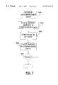
- FIG. 7 is a flow diagram showing a high level representation of the compression process.
- FIG. 8 is a flow diagram showing a high level representation of the decompression process.
- FIG. 9 is a more detailed pictorial representation of a portion of data.
- FIG. 10 is a high level diagram showing the typical environment of the present invention.
- FIG. 11 is a representation of a small data segment that is stored on a data storage device.
- FIG. 12 is a representation of a small data segment that is stored on a data storage device showing the use of a special code.
- FIG. 13 shows the compression operation in a block diagram format.
- FIG. 14 shows the decompression operation in a block diagram format.
- the present invention is not limited to a specific embodiment illustrated herein.
- the present invention allows the compression engine to store meta-data in the compressed record. Additionally, there are expansion joints placed to allow for a reasonable amount of data expansion. Markers are added to the compression stream to indicate various things.
- a first marker is the compressed record marker.
- Each compressed record has a marker to indicate the start of the compressed data.
- the storage system knows the rough location of the start of the compressed record. It starts reading in that region and scans the data for the record start marker.
- a second marker is used to indicate free space. When compressed data is stored on the disk drive, free space is reserved so that future compression of the same, or modified, data has the ability to expand slightly without causing the data to be written to a different location.
- a third type of marker is the format pattern marker.
- Compression algorithms generally compress the format pattern very tightly. However, the expectation is that the host will write useful data to the storage device. The compressor is fed typical data in the region of the format pattern, but a marker is set in front of this data to allow the format pattern to be returned rather than the typical data.
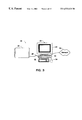
- FIG. 3 shows a computer system 20 having a host computer 22 connected to a data storage system 24 via an I/O interface bus 26 .
- Host computer 22 is a general purpose computer that can be configured, for example, as a server or workstation.
- Computer 22 has a visual display monitor 28 , a central processing unit (CPU) 30 , a keyboard 32 , and a mouse 34 .
- Other data entry and output peripherals may also be included, such as a printer, tape, CD-ROM, network interfaces, and so forth.
- the host computer 22 is coupled to a network 36 to serve data from the data storage system 24 to one or more clients (not shown).
- the data storage system 24 holds user data and other information.
- the data storage system 24 is a hierarchical RAID system that is capable of storing data according to different redundancy schemes.
- the host computer 22 provides an interface for an administrator to configure the memory space in the RAID system 24 , run diagnostics, evaluate performance, and otherwise manage the RAID storage system.
- FIG. 4 shows the host computer 22 and data storage system 24 in more detail.
- the computer 22 has a processor 40 , a volatile memory 42 (i.e., RAM), a keyboard 32 , a mouse 34 , a non-volatile memory 44 (e.g., ROM, hard disk, floppy disk, CD-ROM, etc.), and a display 28 .
- An administrator module 46 is stored in memory 44 and executes on processor 40 .
- the administrator module 46 provides management functions such as diagnostics, performance review, LUN arrangement analysis, and capacity analysis.
- the administrator module 48 supports a storage manager graphical user interface (UI) 48 that presents a visual interface on the display 28 .
- UI graphical user interface
- the data storage system 24 has a disk array 50 with multiple storage disks 52 , a disk array controller 54 , and a RAID management system 56 .
- the disk array controller 54 is coupled to the disk array 50 via one or more interface buses 58 , such as a small computer system interface (SCSI).
- the RAID management system 56 is coupled to the disk array controller 54 via an interface protocol 60 . It is noted that the RAID management system 56 can be embodied as a separate component (as shown), or within the disk array controller 54 , or within the host computer 22 .
- the RAID management system 56 is preferably a software module that runs on the processing unit of the data storage system 24 , or on the processor 40 of the computer 22 .
- the disk array controller 54 coordinates data transfer to and from the disk array 50 .
- the disk array controller 54 has two identical controller boards: a first disk array controller 54 a and a second disk array controller 54 b.
- the parallel controllers enhance reliability by providing continuous backup and redundancy in the event that one controller becomes inoperable.
- the parallel controllers 54 a and 54 b have respective mirrored memories 62 a and 62 b.
- the mirrored memories 62 a and 62 b are preferably implemented as battery-backed, non-volatile RAMs (NVRAMs).
- NVRAMs non-volatile RAMs
- the mirrored memories 62 a and 62 b store several types of information.
- the mirrored memories 62 a and 62 b maintain duplicate copies of a cohesive memory map of the storage space in disk array 50 . This memory map tracks where data and redundancy information are stored on the disk, and where available free space is located.
- the view of the mirrored memories is consistent across the hot-plug interface, appearing the same to external processes seeking to read or write data.
- the mirrored memories 62 a and 62 b also maintain a read cache that holds data being read from the disk array 50 . Every read request is shared between the controllers.
- the mirrored memories 62 a and 62 b further maintain two duplicative copies of a write cache. Each write cache temporarily stores data before it is written out to the disk array 50 .
- FIG. 5 the record marker will be described in more detail. It is known for a storage apparatus to receive host data and arrange the data into fixed size groups independent of the data structure.
- a RAID system data is handled in Relocation Blocks (RB). While the data is handled in RBs, not all operations affect the entire RB. For example, if a user modifies only a portion of an RB, it is very desirable to only modify the portion of the RB that was affected. To decompress and entire RB, modify the affected portion, and then recompress the RB would create a significant performance degradation.
- RB Relocation Blocks
- the preferred embodiment solves this problem by adding the record marker to indicate the beginning of different sections of the RB.
- the preferred embodiment places these markers every four sectors, where a sector is 512 bytes, of uncompressed data.
- the firmware points the decompression engine in the general area of the record and the specialized decompression algorithm searches for the record marker—which is mixed in with the random data patterns from compression operations—and begins the decompression operations at the exact byte location required.
- RB 1 -RB 3 three RBs are shown (RB 1 -RB 3 ) with RB 2 ( 132 ) shown in greater detail.
- a Mstart record marker This record marker indicates the start of a new RB.
- Additional record markers are added and shown as M 1 -M 4 .
- these record markers are placed every 2K bytes of uncompressed data.
- expansion joints 134 are also shown.
- uncompressed data is sent from the host ( 22 ) to the storage system ( 24 ).
- the host may have operating system (OS) information embedded in the uncompressed data, however, the storage system generally does not make use this OS information.
- OS operating system
- the storage system 48 first places ( 552 ) an Mstart record marker to indicate that a new RB is starting.
- the data is compressed ( 554 ) using a lossless data compression algorithm.
- the M 1 record marker is placed ( 556 ) in the compressed data stream.
- This record marker indicates to the decompressor that it can start decompressing at this point.
- the dictionary is reset; likewise, if the compression engine is using an arithmetic compression, the probability table is reset; other compression algorithms may require their own method to insure that decompression can start at this point.
- the compression engine continues ( 558 ) to compress the uncompressed data. Again after compressing ( 554 ) 2K byte of uncompressed data, the M 2 record marker is placed ( 556 ) in the compressed data. This process continues until the original RB has been compressed.
- the storage system determines the approximate location of the Mx record marker ( 570 ).
- a block of data is retrieved from the storage devices ( 50 ) starting at the approximate location ( 572 ).
- the specialized decompression algorithm searches ( 574 + 576 ) for the Mx record marker—which is mixed in with the random data patterns from compression operations—and begins the decompression operations ( 580 + 582 ) at the exact byte location required.
- expansion joints allow compression records to expand slightly or shrink any amount.
- expansion joints are added at the end of each 4-sector block of physical storage space and consume about 10 percent of the total storage space. This causes additional disk space consumed by the expansion joints to remain constant regardless of the compression ratio.
- Expansion joints are marked be inserting expansion joint meta-data markers into the compressed data stream.
- the expansion joint is a series of expansion joint markers in the compressed data stream. During decompression operation, whenever expansion joint is encountered, the decompressor skips the expansion joint markers and continues when compressed data is encountered.
- a merge operation consists of the following steps.
- the affected data When new data is added to a portion of the existing RB, the affected data must be read, modified and then written to the storage device.
- the affected data is read between record markers M 1 and M 2 .
- the system approximates the location of record marker M 1 and passes it to the decompressor.
- the decompressor finds record marker M 1 and then decompresses the data until record marker M 2 skipping over the expansion joint markers 134 .
- Data before record marker M 1 is not be modified on the disk drive.
- the compression engine places the newly compressed data ( 137 ) behind record marker M 1 .
- the newly compressed data required more space than the original data, therefore the remaining expansion joint ( 134 A) is smaller than the original expansion joint ( 134 ). Finally, the result is written to disk as 132 A shows. Similarly, if the newly compressed data had a higher compression ratio and therefore required less space to store, the expansion joint would expand.
- data is generally managed in discrete blocks of data (the RBs).
- the RBs When the host writes a portion of the RB, the portion the host did not write remains the format pattern. Thus, when the host reads the portion of the RB that was not previously written, it expects to receive the format pattern.
- the format pattern is quite repetitive and compresses well given an adaptive compression algorithm. This actually creates a problem when dealing with RBs that are only partially written. The problem comes in the merge operation. Any time the user writes real data over the format pattern, the newly compressed data would be much larger than the compressed format pattern.
- the size of the expansion joints are intended to soak up the small deviations resulting from merge operations, not fundamental shifts in the type of data stored.
- This invention resolves this problem by placing a Format Marker at the start of each block of data inside the RB.
- the format marker directs the decompressor to ignore the actual data decompressed and simply provide the format pattern. That way, when the record is initially compressed, similar data can be used to create the compressed record. The similar data is based on the data actually written by the host. The compression record that results from the compression of the similar data can be thought of as a placeholder for future data that is to be merged.
- FIG. 5 shows an RB in detail.
- Mstart record marker and M 1 -M 4 record markers placed regularly throughout the RB.
- expansion joint markers 134 shown. This figure shows how the format marker can used to indicate that the following block is not completely used.
- block 140 is only partially used.
- a portion ( 141 ) contains data, and a portion 142 should be interpreted as format pattern.
- FM format marker
- FM 143 is followed by additional information ( 144 ) indicating which sectors are in use and which should be interpreted as format pattern.
- Each bit in 144 indicates if a particular sector is valid data or invalid data.
- sectors 1 - 3 contain valid, compressed data while sector 4 contains invalid compressed data.
- the decompression engine interprets FM 143 and the following information 144 to properly decompress the data.
- the decompression engine ignores the invalid data stored in sector 4 and instead inserts format data into the uncompressed data stream.
- FIG. 9 represents this information using 4 bits, any number of bits could be used.
- an eight bit number follows the FM, but only four of the eight bits are used.
- the number of bits, as is the block size and RB size, is determined by the system requirements.
- decompression may start at a marker (either a record marker and a format marker). To accomplish this depends on the type of data compression used. If a dictionary based compression method such as LZW is used, the at a marker, the compression engine must flush the dictionary at a marker; an RLE type compression must place a control word at this boundary. Arithmetic encoding must reset the probability tables. Other compression schemes may require their own method.
- FIG. 10 shows a high level diagram of a compression system in accordance with the present invention.
- Compression block 95 represents a lossless data compression method, either a presently known method or one not yet created.
- Output from the compressor is further processed by Meta-Data Insertion block 96 .
- Meta-Data Insertion block post processes the data stream from the compressor in order to add the necessary markers. It may also allocate free space by inserting a stream of expansion marker.
- FIG. 11 is a representation of a small data segment that is stored on a data storage device.
- Each block represent a multi-bit value; D blocks represent compressed data, M blocks indicate the start of a compressed record marker, F blocks represent free space marker.
- the alignment of the compressed data relative to the represented code words does not matter. For example, the compression engine could take some of the first “D” ( 121 ) and some of the next “D” and interpret it as any compressed code that makes sense to the compression scheme.
- the alignment of the “M” and “F” markers is important. Because when searching for markers during decompression, the alignment must be known so that the proper search for the “M” and “F” markers can take place without knowledge of the compressed data structure. Any arbitrary alignment is possible provided that decompression process knows the alignment used.
- the compressed data does not include binary output that would mimic a meta-data marker, something must be done to avoid falsely detecting a marker in the compressed data. Detecting any false marker and subsequently marking the false markers with another marker accomplishes this.
- FIG. 12 there is some data that mimics a marker (M′).
- a special marker called “I” ignore
- I is added to indicate that the (M′) is not a valid marker that it is indeed valid compressed data.
- the decompression pre-process engine engine senses the “I”, it passes the the false marker (M′) to the decompression engine and discards the “I”.
- M and I meta-data may have any value, numbers with all zeros or all ones should generally be avoided because those codes are common in compressed data streams.
- code words can be reserved to signal to the compressor that it is a meta-data for the expansion joint as described above.
- code word FE is the record marker.
- a second byte just after the FE is used to encode the record marker number.
- the Format Marker (FM) is represented by the reserved code word FD. As with the record marker, the format marker is followed by a byte used to encode the validity of the data.
- Command Interpreter 201 receives commands from the system and controls the operation of the compression engine.
- Command Interpreter 201 may be implemented in software, firmware, or hardware using a state machine or combinatory logic.
- the system must provide data to the input data buffer 202 A, handle compressed data from the output buffer 207 A and provide instructions to the Command Interpreter 201 .
- Command Interpreter 201 controls the operation of the compression and decompression process.
- Command Interpreter 201 resets Dictionary 203 A and then enables Compressor 204 A.
- Compressor 204 A compresses data received from input Data Buffer 202 A and outputs compressed data.
- Compressor 204 A updates the contents of Dictionary 203 A in accordance with the compression method.
- Compressor 204 A may be implemented in hardware; however, it may also be implemented in software, firmware, or a combination of any of the above.
- Compressor 205 A outputs compressed data to Meta Data Insertion Logic 205 A.
- Meta Data Insertion 205 A inserts the meta-data (Record Marker, Expansion Joints, and Format Marker, Ignore Marker, if needed)) into the compressed data stream.
- some meta-data requires the Command Interpreter 201 to reset dictionary 203 A.
- Data form Meta Data Insertion Logic 205 A is packed ( 206 A) and output ( 207 A) to the system for further processing.
- FIG. 14 shows a similar block diagram for decompression.
- Command Interpreter 201 receives commands from the system and controls the operation of the decompression engine.
- the system must provide compressed data to the input data buffer 202 B, handle uncompressed data from the output buffer 207 B and provide instructions to the Command Interpreter 201 .
- Command Interpreter 201 controls the operation of the decompression process.
- the compressed data passes through the Meta Data logic 205 B where all meta-data is striped from the data stream and passed to Command Interpreter 201 .
- Meta data is interpreted by Command Interpreter 201 . For example, each time a Record Marker is encountered, Command Interpreter 201 must reset Dictionary 203 B.
- Decompressor 204 B After all meta-data has been striped from the compressed data, the compressed data is passed to Decompressor 204 B.
- Decompressor 204 B decompresses compressed data and outputs uncompressed data.
- Decompressor 204 B updates the contents of Dictionary 203 B in accordance with the decompression method.
- Decompressor 204 B may be implemented in hardware; however, it may also be implemented in software, firmware, or a combination of any of the above.
- Decompressor 20 B outputs uncompressed data to Word Packing 206 B and finally to output Buffer 207 B.
Abstract
Description
Claims (13)
Priority Applications (1)
| Application Number | Priority Date | Filing Date | Title |
|---|---|---|---|
| US09/426,831 US6532121B1 (en) | 1999-10-25 | 1999-10-25 | Compression algorithm with embedded meta-data for partial record operation augmented with expansion joints |
Applications Claiming Priority (1)
| Application Number | Priority Date | Filing Date | Title |
|---|---|---|---|
| US09/426,831 US6532121B1 (en) | 1999-10-25 | 1999-10-25 | Compression algorithm with embedded meta-data for partial record operation augmented with expansion joints |
Publications (1)
| Publication Number | Publication Date |
|---|---|
| US6532121B1 true US6532121B1 (en) | 2003-03-11 |
Family
ID=23692383
Family Applications (1)
| Application Number | Title | Priority Date | Filing Date |
|---|---|---|---|
| US09/426,831 Expired - Lifetime US6532121B1 (en) | 1999-10-25 | 1999-10-25 | Compression algorithm with embedded meta-data for partial record operation augmented with expansion joints |
Country Status (1)
| Country | Link |
|---|---|
| US (1) | US6532121B1 (en) |
Cited By (51)
| Publication number | Priority date | Publication date | Assignee | Title |
|---|---|---|---|---|
| US20020165847A1 (en) * | 2001-05-02 | 2002-11-07 | Mccartney Jason | Logical semantic compression |
| US20020169758A1 (en) * | 2001-05-14 | 2002-11-14 | Arman Toorians | Apparatus and methods for reducing compression and decompression time in a computer system |
| US20020191692A1 (en) * | 2001-02-13 | 2002-12-19 | Realtime Data, Llc | Bandwidth sensitive data compression and decompression |
| US20030135845A1 (en) * | 2001-12-14 | 2003-07-17 | Mitsubishi Denki Kabushiki Kaisha | Instruction code conversion apparatus creating an instruction code including a second code converted from a first code |
| US20030145166A1 (en) * | 2002-01-28 | 2003-07-31 | International Business Machines Corporation | Data processing method, data processing system, and program |
| US20030191876A1 (en) * | 2000-02-03 | 2003-10-09 | Fallon James J. | Data storewidth accelerator |
| US20040042506A1 (en) * | 2000-10-03 | 2004-03-04 | Realtime Data, Llc | System and method for data feed acceleration and encryption |
| US20060005069A1 (en) * | 2004-07-01 | 2006-01-05 | Gaertner Mark A | Method and system for increasing data storage reliability and efficiency via compression |
| US20060015650A1 (en) * | 1999-03-11 | 2006-01-19 | Fallon James J | System and methods for accelerated data storage and retrieval |
| US20060136365A1 (en) * | 2004-04-26 | 2006-06-22 | Storewiz Inc. | Method and system for compression of data for block mode access storage |
| US20060184687A1 (en) * | 1999-03-11 | 2006-08-17 | Fallon James J | System and methods for accelerated data storage and retrieval |
| US20060184505A1 (en) * | 2004-04-26 | 2006-08-17 | Storewiz, Inc. | Method and system for compression of files for storage and operation on compressed files |
| US20060181441A1 (en) * | 1998-12-11 | 2006-08-17 | Fallon James J | Content independent data compression method and system |
| US20060190643A1 (en) * | 2004-04-26 | 2006-08-24 | Storewiz, Inc. | Method and system for compression of data for block mode access storage |
| US20060230014A1 (en) * | 2004-04-26 | 2006-10-12 | Storewiz Inc. | Method and system for compression of files for storage and operation on compressed files |
| US7155445B1 (en) * | 2004-02-05 | 2006-12-26 | Cingular Wireless Ii, Llc | System and method for self-recovering real-time data-feed compression and archiving |
| US20070016694A1 (en) * | 2001-12-17 | 2007-01-18 | Isaac Achler | Integrated circuits for high speed adaptive compression and methods therefor |
| US7200603B1 (en) * | 2004-01-08 | 2007-04-03 | Network Appliance, Inc. | In a data storage server, for each subsets which does not contain compressed data after the compression, a predetermined value is stored in the corresponding entry of the corresponding compression group to indicate that corresponding data is compressed |
| US20070083746A1 (en) * | 2000-02-03 | 2007-04-12 | Realtime Data Llc | Systems and methods for accelerated loading of operating systems and application programs |
| US20070091500A1 (en) * | 2005-10-21 | 2007-04-26 | Microsoft Corporation | Method and apparatus for improving the performance of a disk drive |
| US20070156698A1 (en) * | 2005-12-22 | 2007-07-05 | Alexander Gebhart | Systems and methods for finding log files generated by a distributed computer |
| WO2007138600A2 (en) * | 2006-05-31 | 2007-12-06 | Storwize Ltd. | Method and system for transformation of logical data objects for storage |
| US20080104484A1 (en) * | 2006-10-31 | 2008-05-01 | Jacobson Michael B | Mass storage system and method |
| US20080306971A1 (en) * | 2007-06-07 | 2008-12-11 | Motorola, Inc. | Method and apparatus to bind media with metadata using standard metadata headers |
| US20090006844A1 (en) * | 2007-06-28 | 2009-01-01 | Wing Daniel G | Verifying cryptographic identity during media session initialization |
| US20090063856A1 (en) * | 2007-08-31 | 2009-03-05 | Zaheer Aziz | System and Method for Identifying Encrypted Conference Media Traffic |
| US7508609B2 (en) | 2006-10-25 | 2009-03-24 | Spectra Logic Corporation | Formatted storage media providing space for encrypted text and dedicated space for clear text |
| US7529988B1 (en) * | 2003-09-02 | 2009-05-05 | Advanced Micro Devices, Inc. | Storage of descriptive information in user defined fields of failure bitmaps in integrated circuit technology development |
| US20090168892A1 (en) * | 2007-12-28 | 2009-07-02 | Cisco Technology, Inc. | System and Method for Securely Transmitting Video Over a Network |
| US20090193040A1 (en) * | 2008-01-29 | 2009-07-30 | Mitel Networks Corporation | System and method for storing a program using partial compression |
| US20100281340A1 (en) * | 2009-04-30 | 2010-11-04 | International Business Machines Corporation | Adaptive endurance coding of non-volatile memories |
| US20110099344A1 (en) * | 2009-10-28 | 2011-04-28 | International Business Machines Corporation | Facilitating data compression during replication using a compressible configuration bit |
| US20110218974A1 (en) * | 2005-04-21 | 2011-09-08 | Jonathan Amit | Systems and methods for compressing files for storage and operation on compressed files |
| US20110219144A1 (en) * | 2005-04-21 | 2011-09-08 | Jonathan Amit | Systems and methods for compression of data for block mode access storage |
| US8108599B2 (en) | 2004-11-03 | 2012-01-31 | Spectra Logic Corporation | Erasure techniques for emulating streamed data format for non tape media |
| USRE43558E1 (en) * | 2001-12-17 | 2012-07-31 | Sutech Data Solutions Co., Llc | Interface circuits for modularized data optimization engines and methods therefor |
| US8692695B2 (en) | 2000-10-03 | 2014-04-08 | Realtime Data, Llc | Methods for encoding and decoding data |
| US8738838B2 (en) | 2010-04-09 | 2014-05-27 | Samsung Electronics Co., Ltd. | Method, device and system for storing data in storage media using a reference condition |
| US8769311B2 (en) | 2006-05-31 | 2014-07-01 | International Business Machines Corporation | Systems and methods for transformation of logical data objects for storage |
| US8769374B2 (en) | 2010-10-13 | 2014-07-01 | International Business Machines Corporation | Multi-write endurance and error control coding of non-volatile memories |
| US8838890B2 (en) | 2011-04-14 | 2014-09-16 | International Business Machines Corporation | Stride based free space management on compressed volumes |
| US8847797B1 (en) * | 2012-05-31 | 2014-09-30 | Google Inc. | Byte-aligned dictionary-based compression and decompression |
| US8880839B2 (en) | 2011-04-14 | 2014-11-04 | International Business Machines Corporation | Writing adjacent tracks to a stride, based on a comparison of a destaging of tracks to a defragmentation of the stride |
| US8972360B2 (en) | 2011-05-23 | 2015-03-03 | International Business Machines Corporation | Position invariant compression of files within a multi-level compression scheme |
| US9007710B1 (en) * | 2014-08-27 | 2015-04-14 | Seagate Technology | Rewrite operation for recording bands |
| US9143546B2 (en) | 2000-10-03 | 2015-09-22 | Realtime Data Llc | System and method for data feed acceleration and encryption |
| US10027984B2 (en) | 2016-11-30 | 2018-07-17 | Hewlett Packard Enterprise Development Lp | Methods and systems for efficiently reading a data block from a data seglet with compressed data blocks |
| US10592173B2 (en) * | 2018-01-10 | 2020-03-17 | International Business Machines Corporation | Increasing storage efficiency of a data protection technique |
| WO2021096822A1 (en) * | 2019-11-13 | 2021-05-20 | Microsoft Technology Licensing, Llc | Partial downloads of compressed data |
| US11295031B2 (en) | 2019-10-08 | 2022-04-05 | International Business Machines Corporation | Event log tamper resistance |
| US11392348B2 (en) | 2020-02-13 | 2022-07-19 | International Business Machines Corporation | Ordering records for timed meta-data generation in a blocked record environment |
Citations (12)
| Publication number | Priority date | Publication date | Assignee | Title |
|---|---|---|---|---|
| US5481701A (en) * | 1991-09-13 | 1996-01-02 | Salient Software, Inc. | Method and apparatus for performing direct read of compressed data file |
| US5623701A (en) * | 1995-06-06 | 1997-04-22 | International Business Machines Corporation | Data compression method and structure for a direct access storage device |
| US5630092A (en) * | 1994-10-20 | 1997-05-13 | International Business Machines | System and method for transferring compressed and uncompressed data between storage systems |
| US5644791A (en) * | 1993-11-30 | 1997-07-01 | International Business Machines Corporation | System for storing pointers to initial sectors of variable length n units and storing second pointers within the initial sector of the n unit |
| US5649151A (en) * | 1992-06-29 | 1997-07-15 | Apple Computer, Inc. | Efficient method and apparatus for access and storage of compressed data |
| US5875270A (en) * | 1996-05-28 | 1999-02-23 | Sharp Kabushiki Kaisha | Image display device |
| EP0913761A1 (en) | 1997-10-31 | 1999-05-06 | Hewlett-Packard Company | Data encoding scheme |
| EP0913760A1 (en) | 1997-10-31 | 1999-05-06 | Hewlett-Packard Company | Data encoding scheme |
| EP0913825A2 (en) | 1997-10-31 | 1999-05-06 | Hewlett-Packard Company | Data encoding scheme |
| EP0913762A1 (en) | 1997-10-31 | 1999-05-06 | Hewlett-Packard Company | Data encoding scheme |
| EP0915413A1 (en) | 1997-10-31 | 1999-05-12 | Hewlett-Packard Company | Data encoding scheme with switchable compression |
| US6134062A (en) * | 1997-06-30 | 2000-10-17 | Emc Corporation | Method and apparatus for increasing disc drive performance |
-
1999
- 1999-10-25 US US09/426,831 patent/US6532121B1/en not_active Expired - Lifetime
Patent Citations (12)
| Publication number | Priority date | Publication date | Assignee | Title |
|---|---|---|---|---|
| US5481701A (en) * | 1991-09-13 | 1996-01-02 | Salient Software, Inc. | Method and apparatus for performing direct read of compressed data file |
| US5649151A (en) * | 1992-06-29 | 1997-07-15 | Apple Computer, Inc. | Efficient method and apparatus for access and storage of compressed data |
| US5644791A (en) * | 1993-11-30 | 1997-07-01 | International Business Machines Corporation | System for storing pointers to initial sectors of variable length n units and storing second pointers within the initial sector of the n unit |
| US5630092A (en) * | 1994-10-20 | 1997-05-13 | International Business Machines | System and method for transferring compressed and uncompressed data between storage systems |
| US5623701A (en) * | 1995-06-06 | 1997-04-22 | International Business Machines Corporation | Data compression method and structure for a direct access storage device |
| US5875270A (en) * | 1996-05-28 | 1999-02-23 | Sharp Kabushiki Kaisha | Image display device |
| US6134062A (en) * | 1997-06-30 | 2000-10-17 | Emc Corporation | Method and apparatus for increasing disc drive performance |
| EP0913761A1 (en) | 1997-10-31 | 1999-05-06 | Hewlett-Packard Company | Data encoding scheme |
| EP0913760A1 (en) | 1997-10-31 | 1999-05-06 | Hewlett-Packard Company | Data encoding scheme |
| EP0913825A2 (en) | 1997-10-31 | 1999-05-06 | Hewlett-Packard Company | Data encoding scheme |
| EP0913762A1 (en) | 1997-10-31 | 1999-05-06 | Hewlett-Packard Company | Data encoding scheme |
| EP0915413A1 (en) | 1997-10-31 | 1999-05-12 | Hewlett-Packard Company | Data encoding scheme with switchable compression |
Cited By (185)
| Publication number | Priority date | Publication date | Assignee | Title |
|---|---|---|---|---|
| US20060181441A1 (en) * | 1998-12-11 | 2006-08-17 | Fallon James J | Content independent data compression method and system |
| US10033405B2 (en) | 1998-12-11 | 2018-07-24 | Realtime Data Llc | Data compression systems and method |
| US8502707B2 (en) | 1998-12-11 | 2013-08-06 | Realtime Data, Llc | Data compression systems and methods |
| US8643513B2 (en) | 1998-12-11 | 2014-02-04 | Realtime Data Llc | Data compression systems and methods |
| US9054728B2 (en) | 1998-12-11 | 2015-06-09 | Realtime Data, Llc | Data compression systems and methods |
| US7714747B2 (en) | 1998-12-11 | 2010-05-11 | Realtime Data Llc | Data compression systems and methods |
| US8717203B2 (en) | 1998-12-11 | 2014-05-06 | Realtime Data, Llc | Data compression systems and methods |
| US8933825B2 (en) | 1998-12-11 | 2015-01-13 | Realtime Data Llc | Data compression systems and methods |
| US20060181442A1 (en) * | 1998-12-11 | 2006-08-17 | Fallon James J | Content independent data compression method and system |
| US8719438B2 (en) | 1999-03-11 | 2014-05-06 | Realtime Data Llc | System and methods for accelerated data storage and retrieval |
| US8275897B2 (en) | 1999-03-11 | 2012-09-25 | Realtime Data, Llc | System and methods for accelerated data storage and retrieval |
| US10019458B2 (en) | 1999-03-11 | 2018-07-10 | Realtime Data Llc | System and methods for accelerated data storage and retrieval |
| US20060015650A1 (en) * | 1999-03-11 | 2006-01-19 | Fallon James J | System and methods for accelerated data storage and retrieval |
| US8756332B2 (en) | 1999-03-11 | 2014-06-17 | Realtime Data Llc | System and methods for accelerated data storage and retrieval |
| US7415530B2 (en) * | 1999-03-11 | 2008-08-19 | Realtime Data Llc | System and methods for accelerated data storage and retrieval |
| US8504710B2 (en) * | 1999-03-11 | 2013-08-06 | Realtime Data Llc | System and methods for accelerated data storage and retrieval |
| US20060184696A1 (en) * | 1999-03-11 | 2006-08-17 | Fallon James J | System and methods for accelerated data storage and retrieval |
| US20060184687A1 (en) * | 1999-03-11 | 2006-08-17 | Fallon James J | System and methods for accelerated data storage and retrieval |
| US20070067483A1 (en) * | 1999-03-11 | 2007-03-22 | Realtime Data Llc | System and methods for accelerated data storage and retrieval |
| US9116908B2 (en) | 1999-03-11 | 2015-08-25 | Realtime Data Llc | System and methods for accelerated data storage and retrieval |
| US20060195601A1 (en) * | 1999-03-11 | 2006-08-31 | Fallon James J | System and methods for accelerated data storage and retrieval |
| US20060190644A1 (en) * | 2000-02-03 | 2006-08-24 | Fallon James J | Data storewidth accelerator |
| US8112619B2 (en) | 2000-02-03 | 2012-02-07 | Realtime Data Llc | Systems and methods for accelerated loading of operating systems and application programs |
| US8880862B2 (en) | 2000-02-03 | 2014-11-04 | Realtime Data, Llc | Systems and methods for accelerated loading of operating systems and application programs |
| US9792128B2 (en) | 2000-02-03 | 2017-10-17 | Realtime Data, Llc | System and method for electrical boot-device-reset signals |
| US20030191876A1 (en) * | 2000-02-03 | 2003-10-09 | Fallon James J. | Data storewidth accelerator |
| US20070083746A1 (en) * | 2000-02-03 | 2007-04-12 | Realtime Data Llc | Systems and methods for accelerated loading of operating systems and application programs |
| US8090936B2 (en) | 2000-02-03 | 2012-01-03 | Realtime Data, Llc | Systems and methods for accelerated loading of operating systems and application programs |
| US8723701B2 (en) | 2000-10-03 | 2014-05-13 | Realtime Data Llc | Methods for encoding and decoding data |
| US10419021B2 (en) | 2000-10-03 | 2019-09-17 | Realtime Data, Llc | Systems and methods of data compression |
| US9143546B2 (en) | 2000-10-03 | 2015-09-22 | Realtime Data Llc | System and method for data feed acceleration and encryption |
| US8692695B2 (en) | 2000-10-03 | 2014-04-08 | Realtime Data, Llc | Methods for encoding and decoding data |
| US8717204B2 (en) | 2000-10-03 | 2014-05-06 | Realtime Data Llc | Methods for encoding and decoding data |
| US20040042506A1 (en) * | 2000-10-03 | 2004-03-04 | Realtime Data, Llc | System and method for data feed acceleration and encryption |
| US10284225B2 (en) | 2000-10-03 | 2019-05-07 | Realtime Data, Llc | Systems and methods for data compression |
| US9667751B2 (en) | 2000-10-03 | 2017-05-30 | Realtime Data, Llc | Data feed acceleration |
| US20070174209A1 (en) * | 2000-10-03 | 2007-07-26 | Realtime Data Llc | System and method for data feed acceleration and encryption |
| US9141992B2 (en) | 2000-10-03 | 2015-09-22 | Realtime Data Llc | Data feed acceleration |
| US9859919B2 (en) | 2000-10-03 | 2018-01-02 | Realtime Data Llc | System and method for data compression |
| US9967368B2 (en) | 2000-10-03 | 2018-05-08 | Realtime Data Llc | Systems and methods for data block decompression |
| US8742958B2 (en) | 2000-10-03 | 2014-06-03 | Realtime Data Llc | Methods for encoding and decoding data |
| US7777651B2 (en) | 2000-10-03 | 2010-08-17 | Realtime Data Llc | System and method for data feed acceleration and encryption |
| US8934535B2 (en) | 2001-02-13 | 2015-01-13 | Realtime Data Llc | Systems and methods for video and audio data storage and distribution |
| US9769477B2 (en) | 2001-02-13 | 2017-09-19 | Realtime Adaptive Streaming, LLC | Video data compression systems |
| US10212417B2 (en) | 2001-02-13 | 2019-02-19 | Realtime Adaptive Streaming Llc | Asymmetric data decompression systems |
| US20020191692A1 (en) * | 2001-02-13 | 2002-12-19 | Realtime Data, Llc | Bandwidth sensitive data compression and decompression |
| US9762907B2 (en) | 2001-02-13 | 2017-09-12 | Realtime Adaptive Streaming, LLC | System and methods for video and audio data distribution |
| US8553759B2 (en) | 2001-02-13 | 2013-10-08 | Realtime Data, Llc | Bandwidth sensitive data compression and decompression |
| US8073047B2 (en) | 2001-02-13 | 2011-12-06 | Realtime Data, Llc | Bandwidth sensitive data compression and decompression |
| US8054879B2 (en) | 2001-02-13 | 2011-11-08 | Realtime Data Llc | Bandwidth sensitive data compression and decompression |
| US8929442B2 (en) | 2001-02-13 | 2015-01-06 | Realtime Data, Llc | System and methods for video and audio data distribution |
| US8867610B2 (en) | 2001-02-13 | 2014-10-21 | Realtime Data Llc | System and methods for video and audio data distribution |
| US7257648B2 (en) | 2001-05-02 | 2007-08-14 | Microsoft Corporation | Logical semantic compression |
| US7152121B2 (en) | 2001-05-02 | 2006-12-19 | Microsoft Corporation | Logical semantic compression |
| US20020165847A1 (en) * | 2001-05-02 | 2002-11-07 | Mccartney Jason | Logical semantic compression |
| US7082478B2 (en) * | 2001-05-02 | 2006-07-25 | Microsoft Corporation | Logical semantic compression |
| US7149812B2 (en) | 2001-05-02 | 2006-12-12 | Microsoft Corporation | Logical semantic compression |
| US20050253741A1 (en) * | 2001-05-02 | 2005-11-17 | Microsoft Corporation | Logical semantic compression |
| US20050246364A1 (en) * | 2001-05-02 | 2005-11-03 | Microsoft Corporation | Logical semantic compression |
| US20050149553A1 (en) * | 2001-05-02 | 2005-07-07 | Microsoft Corporation | Logical semantic compression |
| US20020169758A1 (en) * | 2001-05-14 | 2002-11-14 | Arman Toorians | Apparatus and methods for reducing compression and decompression time in a computer system |
| US6871274B2 (en) * | 2001-12-14 | 2005-03-22 | Renesas Technology Corp. | Instruction code conversion apparatus creating an instruction code including a second code converted from a first code |
| US20030135845A1 (en) * | 2001-12-14 | 2003-07-17 | Mitsubishi Denki Kabushiki Kaisha | Instruction code conversion apparatus creating an instruction code including a second code converted from a first code |
| US20100077141A1 (en) * | 2001-12-17 | 2010-03-25 | Isaac Achler | Adaptive Compression and Decompression |
| US8504725B2 (en) | 2001-12-17 | 2013-08-06 | Sutech Data Solutions Co., Llc | Adaptive compression and decompression |
| US8639849B2 (en) | 2001-12-17 | 2014-01-28 | Sutech Data Solutions Co., Llc | Integrated circuits for high speed adaptive compression and methods therefor |
| USRE43558E1 (en) * | 2001-12-17 | 2012-07-31 | Sutech Data Solutions Co., Llc | Interface circuits for modularized data optimization engines and methods therefor |
| US20070016694A1 (en) * | 2001-12-17 | 2007-01-18 | Isaac Achler | Integrated circuits for high speed adaptive compression and methods therefor |
| US20030145166A1 (en) * | 2002-01-28 | 2003-07-31 | International Business Machines Corporation | Data processing method, data processing system, and program |
| US7076607B2 (en) * | 2002-01-28 | 2006-07-11 | International Business Machines Corporation | System, method, and apparatus for storing segmented data and corresponding parity data |
| US7529988B1 (en) * | 2003-09-02 | 2009-05-05 | Advanced Micro Devices, Inc. | Storage of descriptive information in user defined fields of failure bitmaps in integrated circuit technology development |
| US7200603B1 (en) * | 2004-01-08 | 2007-04-03 | Network Appliance, Inc. | In a data storage server, for each subsets which does not contain compressed data after the compression, a predetermined value is stored in the corresponding entry of the corresponding compression group to indicate that corresponding data is compressed |
| US7155445B1 (en) * | 2004-02-05 | 2006-12-26 | Cingular Wireless Ii, Llc | System and method for self-recovering real-time data-feed compression and archiving |
| US8347004B2 (en) | 2004-04-26 | 2013-01-01 | International Business Machines Corporation | Systems and methods for compression of data for block mode access storage |
| US20080313371A1 (en) * | 2004-04-26 | 2008-12-18 | Storewiz Inc. | Method and system for compression of data for block mode access storage |
| US7424482B2 (en) | 2004-04-26 | 2008-09-09 | Storwize Inc. | Method and system for compression of data for block mode access storage |
| US20060230014A1 (en) * | 2004-04-26 | 2006-10-12 | Storewiz Inc. | Method and system for compression of files for storage and operation on compressed files |
| US7970965B2 (en) | 2004-04-26 | 2011-06-28 | Storewize Inc. | Method and system for compression of data for block mode access storage |
| US7979403B2 (en) * | 2004-04-26 | 2011-07-12 | Storewize, Inc. | Method and system for compression of files for storage and operation on compressed files |
| US20060190643A1 (en) * | 2004-04-26 | 2006-08-24 | Storewiz, Inc. | Method and system for compression of data for block mode access storage |
| US20110219186A1 (en) * | 2004-04-26 | 2011-09-08 | Jonathan Amit | Systems and methods for compression of data for block mode access storage |
| US20110218977A1 (en) * | 2004-04-26 | 2011-09-08 | Jonathan Amit | Systems and methods for compression of data for block mode access storage |
| US20110219153A1 (en) * | 2004-04-26 | 2011-09-08 | Jonathan Amit | Systems and methods for compression of data for block mode access storage |
| US20060136365A1 (en) * | 2004-04-26 | 2006-06-22 | Storewiz Inc. | Method and system for compression of data for block mode access storage |
| US8856409B2 (en) | 2004-04-26 | 2014-10-07 | International Business Machines Corporation | Systems and methods for compression of data for block mode access storage |
| US8606763B2 (en) | 2004-04-26 | 2013-12-10 | International Business Machines Corporation | Method and system for compression of files for storage and operation on compressed files |
| US20060184505A1 (en) * | 2004-04-26 | 2006-08-17 | Storewiz, Inc. | Method and system for compression of files for storage and operation on compressed files |
| US20110218976A1 (en) * | 2004-04-26 | 2011-09-08 | Jonathan Amit | Method and system for compression of files for storage and operation on compressed files |
| US8347003B2 (en) | 2004-04-26 | 2013-01-01 | International Business Machines Corporation | Systems and methods for compression of data for block mode access storage |
| US20060005069A1 (en) * | 2004-07-01 | 2006-01-05 | Gaertner Mark A | Method and system for increasing data storage reliability and efficiency via compression |
| US8140744B2 (en) | 2004-07-01 | 2012-03-20 | Seagate Technology Llc | Method and system for increasing data storage reliability and efficiency via compression |
| US8108599B2 (en) | 2004-11-03 | 2012-01-31 | Spectra Logic Corporation | Erasure techniques for emulating streamed data format for non tape media |
| US20110219144A1 (en) * | 2005-04-21 | 2011-09-08 | Jonathan Amit | Systems and methods for compression of data for block mode access storage |
| US8473652B2 (en) | 2005-04-21 | 2013-06-25 | International Business Machines Corporation | Systems and methods for compression of data for block mode access storage |
| US20110218975A1 (en) * | 2005-04-21 | 2011-09-08 | Jonathan Amit | Method and system for compression of files for storage and operation on compressed files |
| US20110218970A1 (en) * | 2005-04-21 | 2011-09-08 | Jonathan Amit | Systems and methods for compression of data for block mode access storage |
| US8677039B2 (en) | 2005-04-21 | 2014-03-18 | International Business Machines Corporation | Systems and methods for compression of data for block mode access storage |
| US8656075B2 (en) | 2005-04-21 | 2014-02-18 | International Business Machines Corporation | Method and system for compression of files for storage and operation on compressed files |
| US8327050B2 (en) | 2005-04-21 | 2012-12-04 | International Business Machines Corporation | Systems and methods for compressing files for storage and operation on compressed files |
| US8285898B2 (en) | 2005-04-21 | 2012-10-09 | International Business Machines Corporation | Method and system for compression of files for storage and operation on compressed files |
| US20110218974A1 (en) * | 2005-04-21 | 2011-09-08 | Jonathan Amit | Systems and methods for compressing files for storage and operation on compressed files |
| US20070091500A1 (en) * | 2005-10-21 | 2007-04-26 | Microsoft Corporation | Method and apparatus for improving the performance of a disk drive |
| US7430091B2 (en) * | 2005-10-21 | 2008-09-30 | Microsoft Corporation | Method and apparatus for improving the performance of a disk drive |
| WO2007049109A2 (en) * | 2005-10-26 | 2007-05-03 | Storewiz Inc. | Method and system for compression of logical data objects for storage |
| WO2007049109A3 (en) * | 2005-10-26 | 2007-07-12 | Storewiz Inc | Method and system for compression of logical data objects for storage |
| US7676474B2 (en) * | 2005-12-22 | 2010-03-09 | Sap Ag | Systems and methods for finding log files generated by a distributed computer |
| US20070156698A1 (en) * | 2005-12-22 | 2007-07-05 | Alexander Gebhart | Systems and methods for finding log files generated by a distributed computer |
| US8832043B2 (en) | 2006-05-31 | 2014-09-09 | International Business Machines Corporation | Method and system for transformation of logical data objects for storage |
| US9262427B2 (en) | 2006-05-31 | 2016-02-16 | International Business Machines Corporation | Systems and methods for transformation of logical data objects for storage |
| US20090307249A1 (en) * | 2006-05-31 | 2009-12-10 | Storwize Ltd. | Method and system for transformation of logical data objects for storage |
| US20090327751A1 (en) * | 2006-05-31 | 2009-12-31 | Haim Koifman | Method and system for transformation of logical data objects for storage |
| WO2007138600A3 (en) * | 2006-05-31 | 2008-11-13 | Storewiz Inc | Method and system for transformation of logical data objects for storage |
| US8626726B2 (en) | 2006-05-31 | 2014-01-07 | International Business Machines Corporation | Method and system for transformation of logical data objects for storage |
| US10268696B2 (en) | 2006-05-31 | 2019-04-23 | International Business Machines Corporation | Systems and methods for transformation of logical data objects for storage |
| US8769311B2 (en) | 2006-05-31 | 2014-07-01 | International Business Machines Corporation | Systems and methods for transformation of logical data objects for storage |
| US9479616B2 (en) | 2006-05-31 | 2016-10-25 | International Business Machines Corporation | Systems and methods for transformation of logical data objects for storage |
| US8782436B2 (en) | 2006-05-31 | 2014-07-15 | International Business Machines Corporation | Method and system for transformation of logical data objects for storage |
| US8788467B2 (en) | 2006-05-31 | 2014-07-22 | International Business Machines Corporation | Systems and methods for transformation of logical data objects for storage |
| US8793510B2 (en) | 2006-05-31 | 2014-07-29 | International Business Machines Corporation | Systems and methods for transformation of logical data objects for storage |
| US8819454B2 (en) | 2006-05-31 | 2014-08-26 | International Business Machines Corporation | Systems and methods for transformation of logical data objects for storage |
| US9110913B2 (en) | 2006-05-31 | 2015-08-18 | International Business Machines Corporation | Systems and methods for transformation of logical data objects for storage |
| US9367555B2 (en) | 2006-05-31 | 2016-06-14 | International Business Machines Corporation | Systems and methods for transformation of logical data objects for storage |
| US9323773B2 (en) | 2006-05-31 | 2016-04-26 | International Business Machines Corporation | Systems and methods for transformation of logical data objects for storage |
| US9317516B2 (en) | 2006-05-31 | 2016-04-19 | International Business Machines Corporation | Systems and methods for transformation of logical data objects for storage |
| US9311320B2 (en) | 2006-05-31 | 2016-04-12 | International Business Machines Corporation | Systems and methods for transformation of logical data objects for storage |
| US9104688B2 (en) | 2006-05-31 | 2015-08-11 | International Business Machines Corporation | Systems and methods for transformation of logical data objects for storage |
| US8868930B2 (en) | 2006-05-31 | 2014-10-21 | International Business Machines Corporation | Systems and methods for transformation of logical data objects for storage |
| US10380071B2 (en) | 2006-05-31 | 2019-08-13 | International Business Machines Corporation | Systems and methods for transformation of logical data objects for storage |
| US20100017423A1 (en) * | 2006-05-31 | 2010-01-21 | Storwize Ltd. | Method and system for transformation of logical data objects for storage |
| US10372680B2 (en) | 2006-05-31 | 2019-08-06 | International Business Machines Corporation | Systems and methods for transformation of logical data objects for storage |
| US9251158B2 (en) | 2006-05-31 | 2016-02-02 | International Business Machines Corporation | Systems and methods for transformation of logical data objects for storage |
| US8924367B2 (en) | 2006-05-31 | 2014-12-30 | International Business Machines Corporation | Method and system for transformation of logical data objects for storage |
| US9176976B2 (en) | 2006-05-31 | 2015-11-03 | International Business Machines Corporation | Systems and methods for transformation of logical data objects for storage |
| US8930329B2 (en) | 2006-05-31 | 2015-01-06 | International Business Machines Corporation | Systems and methods for transformation of logical data objects for storage |
| US20090307250A1 (en) * | 2006-05-31 | 2009-12-10 | Storwize Ltd. | Method and system for transformation of logical data objects for storage |
| WO2007138600A2 (en) * | 2006-05-31 | 2007-12-06 | Storwize Ltd. | Method and system for transformation of logical data objects for storage |
| US8954756B2 (en) | 2006-05-31 | 2015-02-10 | International Business Machines Corporation | Systems and methods for transformation of logical data objects for storage |
| US8954403B2 (en) | 2006-05-31 | 2015-02-10 | International Business Machines Corporation | Systems and methods for transformation of logical data objects for storage |
| US8958482B2 (en) | 2006-05-31 | 2015-02-17 | International Business Machines Corporation | Systems and methods for transformation of logical data objects for storage |
| US8959064B2 (en) | 2006-05-31 | 2015-02-17 | International Business Machines Corporation | Systems and methods for transformation of logical data objects for storage |
| US9218355B2 (en) | 2006-05-31 | 2015-12-22 | International Business Machines Corporation | Systems and methods for transformation of logical data objects for storage |
| US9218297B2 (en) | 2006-05-31 | 2015-12-22 | International Business Machines Corporation | Systems and methods for transformation of logical data objects for storage |
| US20100036863A1 (en) * | 2006-05-31 | 2010-02-11 | Storewize Ltd. | Method and system for transformation of logical data objects for storage |
| US9176975B2 (en) | 2006-05-31 | 2015-11-03 | International Business Machines Corporation | Method and system for transformation of logical data objects for storage |
| US7508609B2 (en) | 2006-10-25 | 2009-03-24 | Spectra Logic Corporation | Formatted storage media providing space for encrypted text and dedicated space for clear text |
| US7840877B2 (en) * | 2006-10-31 | 2010-11-23 | Hewlett-Packard Development Company, L.P. | Mass storage system and method |
| US20080104484A1 (en) * | 2006-10-31 | 2008-05-01 | Jacobson Michael B | Mass storage system and method |
| US7747558B2 (en) * | 2007-06-07 | 2010-06-29 | Motorola, Inc. | Method and apparatus to bind media with metadata using standard metadata headers |
| US20080306971A1 (en) * | 2007-06-07 | 2008-12-11 | Motorola, Inc. | Method and apparatus to bind media with metadata using standard metadata headers |
| US20090006844A1 (en) * | 2007-06-28 | 2009-01-01 | Wing Daniel G | Verifying cryptographic identity during media session initialization |
| US8200959B2 (en) | 2007-06-28 | 2012-06-12 | Cisco Technology, Inc. | Verifying cryptographic identity during media session initialization |
| US8533462B2 (en) | 2007-06-28 | 2013-09-10 | Cisco Technology, Inc. | Verifying cryptographic identity during media session initialization |
| US8417942B2 (en) | 2007-08-31 | 2013-04-09 | Cisco Technology, Inc. | System and method for identifying encrypted conference media traffic |
| US20090063856A1 (en) * | 2007-08-31 | 2009-03-05 | Zaheer Aziz | System and Method for Identifying Encrypted Conference Media Traffic |
| US20090168892A1 (en) * | 2007-12-28 | 2009-07-02 | Cisco Technology, Inc. | System and Method for Securely Transmitting Video Over a Network |
| US8837598B2 (en) | 2007-12-28 | 2014-09-16 | Cisco Technology, Inc. | System and method for securely transmitting video over a network |
| US20090193040A1 (en) * | 2008-01-29 | 2009-07-30 | Mitel Networks Corporation | System and method for storing a program using partial compression |
| US8214425B2 (en) * | 2008-01-29 | 2012-07-03 | Mitel Networks Corporation | System and method for storing a program using partial compression |
| US20100281340A1 (en) * | 2009-04-30 | 2010-11-04 | International Business Machines Corporation | Adaptive endurance coding of non-volatile memories |
| US8341501B2 (en) * | 2009-04-30 | 2012-12-25 | International Business Machines Corporation | Adaptive endurance coding of non-volatile memories |
| US8499221B2 (en) | 2009-04-30 | 2013-07-30 | International Business Machines Corporation | Accessing coded data stored in a non-volatile memory |
| US20110099344A1 (en) * | 2009-10-28 | 2011-04-28 | International Business Machines Corporation | Facilitating data compression during replication using a compressible configuration bit |
| US8468315B2 (en) | 2009-10-28 | 2013-06-18 | International Business Machines Corporation | Facilitating data compression during replication using a compressible configuration bit |
| US8473699B2 (en) | 2009-10-28 | 2013-06-25 | International Business Machines Corporation | Facilitating data compression during replication using a compressible configuration bit |
| US8738838B2 (en) | 2010-04-09 | 2014-05-27 | Samsung Electronics Co., Ltd. | Method, device and system for storing data in storage media using a reference condition |
| US8769374B2 (en) | 2010-10-13 | 2014-07-01 | International Business Machines Corporation | Multi-write endurance and error control coding of non-volatile memories |
| US8880839B2 (en) | 2011-04-14 | 2014-11-04 | International Business Machines Corporation | Writing adjacent tracks to a stride, based on a comparison of a destaging of tracks to a defragmentation of the stride |
| US8880840B2 (en) | 2011-04-14 | 2014-11-04 | International Business Machines Corporation | Writing adjacent tracks to a stride, based on a comparison of a destaging of tracks to a defragmentation of the stride |
| US9286239B2 (en) | 2011-04-14 | 2016-03-15 | International Business Machines Corporation | Writing adjacent tracks to a stride, based on a comparison of a destaging of tracks to a defragmentation of the stride |
| US8838890B2 (en) | 2011-04-14 | 2014-09-16 | International Business Machines Corporation | Stride based free space management on compressed volumes |
| US8843704B2 (en) | 2011-04-14 | 2014-09-23 | International Business Machines Corporation | Stride based free space management on compressed volumes |
| US9418021B2 (en) | 2011-04-14 | 2016-08-16 | International Business Machines Corporation | Writing adjacent tracks to a stride, based on a comparison of a destaging of tracks to a defragmentation of the stride |
| US9298645B2 (en) | 2011-04-14 | 2016-03-29 | International Business Machines Corporation | Writing adjacent tracks to a stride, based on a comparison of a destaging of tracks to a defragmentation of the stride |
| US9086816B2 (en) | 2011-04-14 | 2015-07-21 | International Business Machines Corporation | Writing adjacent tracks to a stride, based on a comparison of a destaging of tracks to a defragmentation of the stride |
| US9086815B2 (en) | 2011-04-14 | 2015-07-21 | International Business Machines Corporation | Writing adjacent tracks to a stride, based on a comparison of a destaging of tracks to a defragmentation of the stride |
| US9086822B2 (en) | 2011-04-14 | 2015-07-21 | International Business Machines Corporation | Writing adjacent tracks to a stride, based on a comparison of a destaging of tracks to a defragmentation of the stride |
| US8972360B2 (en) | 2011-05-23 | 2015-03-03 | International Business Machines Corporation | Position invariant compression of files within a multi-level compression scheme |
| US8847797B1 (en) * | 2012-05-31 | 2014-09-30 | Google Inc. | Byte-aligned dictionary-based compression and decompression |
| US9007710B1 (en) * | 2014-08-27 | 2015-04-14 | Seagate Technology | Rewrite operation for recording bands |
| US9377956B1 (en) * | 2014-08-27 | 2016-06-28 | Seagate Technology Llc | Rewrite operation for recording bands |
| US10027984B2 (en) | 2016-11-30 | 2018-07-17 | Hewlett Packard Enterprise Development Lp | Methods and systems for efficiently reading a data block from a data seglet with compressed data blocks |
| US10592173B2 (en) * | 2018-01-10 | 2020-03-17 | International Business Machines Corporation | Increasing storage efficiency of a data protection technique |
| US11295031B2 (en) | 2019-10-08 | 2022-04-05 | International Business Machines Corporation | Event log tamper resistance |
| WO2021096822A1 (en) * | 2019-11-13 | 2021-05-20 | Microsoft Technology Licensing, Llc | Partial downloads of compressed data |
| US11392348B2 (en) | 2020-02-13 | 2022-07-19 | International Business Machines Corporation | Ordering records for timed meta-data generation in a blocked record environment |
Similar Documents
| Publication | Publication Date | Title |
|---|---|---|
| US6532121B1 (en) | Compression algorithm with embedded meta-data for partial record operation augmented with expansion joints | |
| US5237675A (en) | Apparatus and method for efficient organization of compressed data on a hard disk utilizing an estimated compression factor | |
| JP3225638B2 (en) | Apparatus and method for compressing data and data processing system | |
| US8677039B2 (en) | Systems and methods for compression of data for block mode access storage | |
| US7693859B2 (en) | System and method for detecting file content similarity within a file system | |
| US8347003B2 (en) | Systems and methods for compression of data for block mode access storage | |
| US5394534A (en) | Data compression/decompression and storage of compressed and uncompressed data on a same removable data storage medium | |
| CN102999543B (en) | The efficient data that make use of the similarity of data segment stores | |
| US5732265A (en) | Storage optimizing encoder and method | |
| JP2534465B2 (en) | Data compression apparatus and method | |
| US6597812B1 (en) | System and method for lossless data compression and decompression | |
| US20140105270A1 (en) | System and methods for video and audio data distribution | |
| CN1331058C (en) | Method and system for storing memory compressed data onto memory compressed disks | |
| US8407378B2 (en) | High-speed inline data compression inline with an eight byte data path | |
| US5999936A (en) | Method and apparatus for compressing and decompressing sequential records in a computer system | |
| US7200603B1 (en) | In a data storage server, for each subsets which does not contain compressed data after the compression, a predetermined value is stored in the corresponding entry of the corresponding compression group to indicate that corresponding data is compressed | |
| CN104025010A (en) | Variable length encoding in a storage system | |
| WO1995018997A2 (en) | Virtual memory management system and method using data compression | |
| CN1973287A (en) | Method and system for compression of files for storage and operation on compressed files | |
| WO1995018996A2 (en) | Lossless data compression system and method | |
| US6418449B1 (en) | Method of cloning the file system of a window web operating system by using a bitmap file | |
| US7379940B1 (en) | Focal point compression method and apparatus | |
| US20230152972A1 (en) | Storage system and data processing method in storage system | |
| WO1991019255A1 (en) | Apparatus and method for efficient organization of compressed data on a hard disk | |
| GB2357604A (en) | Cloning computer file system using bitmap file |
Legal Events
| Date | Code | Title | Description |
|---|---|---|---|
| AS | Assignment |
Owner name: HEWLETT-PACKARD COMPANY, COLORADO Free format text: ASSIGNMENT OF ASSIGNORS INTEREST;ASSIGNORS:RUST, ROBERT A.;VOIGT, DOUGLAS L.;REEL/FRAME:010677/0460 Effective date: 19991025 |
|
| STCF | Information on status: patent grant |
Free format text: PATENTED CASE |
|
| AS | Assignment |
Owner name: HEWLETT-PACKARD DEVELOPMENT COMPANY, L.P., TEXAS Free format text: ASSIGNMENT OF ASSIGNORS INTEREST;ASSIGNOR:HEWLETT-PACKARD COMPANY;REEL/FRAME:013862/0623 Effective date: 20030728 |
|
| FPAY | Fee payment |
Year of fee payment: 4 |
|
| FPAY | Fee payment |
Year of fee payment: 8 |
|
| FPAY | Fee payment |
Year of fee payment: 12 |
|
| AS | Assignment |
Owner name: HEWLETT PACKARD ENTERPRISE DEVELOPMENT LP, TEXAS Free format text: ASSIGNMENT OF ASSIGNORS INTEREST;ASSIGNOR:HEWLETT-PACKARD DEVELOPMENT COMPANY, L.P.;REEL/FRAME:037079/0001 Effective date: 20151027 |