US6575907B1 - Determination of fetal weight in utero - Google Patents
Determination of fetal weight in utero Download PDFInfo
- Publication number
- US6575907B1 US6575907B1 US09/351,252 US35125299A US6575907B1 US 6575907 B1 US6575907 B1 US 6575907B1 US 35125299 A US35125299 A US 35125299A US 6575907 B1 US6575907 B1 US 6575907B1
- Authority
- US
- United States
- Prior art keywords
- fetus
- volume
- weight
- utero
- determiner
- Prior art date
- Legal status (The legal status is an assumption and is not a legal conclusion. Google has not performed a legal analysis and makes no representation as to the accuracy of the status listed.)
- Expired - Lifetime
Links
Images


Classifications
-
- A—HUMAN NECESSITIES
- A61—MEDICAL OR VETERINARY SCIENCE; HYGIENE
- A61B—DIAGNOSIS; SURGERY; IDENTIFICATION
- A61B8/00—Diagnosis using ultrasonic, sonic or infrasonic waves
- A61B8/48—Diagnostic techniques
- A61B8/483—Diagnostic techniques involving the acquisition of a 3D volume of data
-
- A—HUMAN NECESSITIES
- A61—MEDICAL OR VETERINARY SCIENCE; HYGIENE
- A61B—DIAGNOSIS; SURGERY; IDENTIFICATION
- A61B5/00—Measuring for diagnostic purposes; Identification of persons
- A61B5/103—Detecting, measuring or recording devices for testing the shape, pattern, colour, size or movement of the body or parts thereof, for diagnostic purposes
- A61B5/107—Measuring physical dimensions, e.g. size of the entire body or parts thereof
- A61B5/1075—Measuring physical dimensions, e.g. size of the entire body or parts thereof for measuring dimensions by non-invasive methods, e.g. for determining thickness of tissue layer
-
- A—HUMAN NECESSITIES
- A61—MEDICAL OR VETERINARY SCIENCE; HYGIENE
- A61B—DIAGNOSIS; SURGERY; IDENTIFICATION
- A61B8/00—Diagnosis using ultrasonic, sonic or infrasonic waves
- A61B8/08—Detecting organic movements or changes, e.g. tumours, cysts, swellings
- A61B8/0866—Detecting organic movements or changes, e.g. tumours, cysts, swellings involving foetal diagnosis; pre-natal or peri-natal diagnosis of the baby
-
- G—PHYSICS
- G01—MEASURING; TESTING
- G01G—WEIGHING
- G01G9/00—Methods of, or apparatus for, the determination of weight, not provided for in groups G01G1/00 - G01G7/00
-
- G—PHYSICS
- G01—MEASURING; TESTING
- G01S—RADIO DIRECTION-FINDING; RADIO NAVIGATION; DETERMINING DISTANCE OR VELOCITY BY USE OF RADIO WAVES; LOCATING OR PRESENCE-DETECTING BY USE OF THE REFLECTION OR RERADIATION OF RADIO WAVES; ANALOGOUS ARRANGEMENTS USING OTHER WAVES
- G01S15/00—Systems using the reflection or reradiation of acoustic waves, e.g. sonar systems
- G01S15/88—Sonar systems specially adapted for specific applications
- G01S15/89—Sonar systems specially adapted for specific applications for mapping or imaging
- G01S15/8906—Short-range imaging systems; Acoustic microscope systems using pulse-echo techniques
- G01S15/8993—Three dimensional imaging systems
-
- Y—GENERAL TAGGING OF NEW TECHNOLOGICAL DEVELOPMENTS; GENERAL TAGGING OF CROSS-SECTIONAL TECHNOLOGIES SPANNING OVER SEVERAL SECTIONS OF THE IPC; TECHNICAL SUBJECTS COVERED BY FORMER USPC CROSS-REFERENCE ART COLLECTIONS [XRACs] AND DIGESTS
- Y10—TECHNICAL SUBJECTS COVERED BY FORMER USPC
- Y10S—TECHNICAL SUBJECTS COVERED BY FORMER USPC CROSS-REFERENCE ART COLLECTIONS [XRACs] AND DIGESTS
- Y10S128/00—Surgery
- Y10S128/916—Ultrasound 3-D imaging
Definitions
- the present invention relates to fetal weight determination generally and more particularly to fetal weight determination based on ultrasonic imaging.
- UCSD radiologists are working on a new ultrasound technology that's guaranteed to produce much clearer images in three dimensions, by Kate Deely, UCSD Perspectives, Spring 1999;
- Imaging software available from A 1 Alpha Space, Inc, of Websites, Calif., U.S.A. and from Echotech 3-D of Hallbergmoos, Germany;
- HDI1500 commercially available from ATL—Advanced Technology Laboratories, Bothell, Wash., U.S.A.;
- Echo-Scan, Echo-View and Compact3-D commercially available from TomTec Imaging Systems GmbH of Unterschleissheim, Germany;
- NetralVUS commercially available from ScImage, Inc. of Los Altos, Calif. 94022, U.S.A.;
- VoxarLib commercially available from Voxar Ltd. of Edinburgh, UK;
- the present invention seeks to provide an improved system for fetal weight determination in utero.
- apparatus for measuring the weight of a fetus in utero including an ultrasonic imager providing at least one ultrasonic image, a volume determiner operative to employ at least one ultrasonic image to provide volume information relating to at least part of the volume of the fetus in utero, and a weight determiner operative to employ the volume information relating to at least part of the volume of the fetus and density information relating to at least part of the volume of the fetus for providing an output indication representing the weight of the fetus in utero.
- the at least one of the volume determiner and the weight determiner is operative to construct a generally full fetal body volume from incomplete volume information based on known correlation information.
- the volume determiner includes computerized image processing based segmenter operative to employ the at least one ultrasonic image to provide size information relating to at least part of the fetus in utero.
- the volume determiner includes a computerized edge detection based segmenter.
- the at least one of the imager and the volume determiner operates on a slice-by-slice basis.
- the volume determiner also includes a measurement tool which provides information relating to at least one of overall fetal volume, volumes of body parts of the fetus, areas of various cross sections of the fetus and sizes of various bones and body parts of the fetus.
- the weight determiner includes a fetal weight calculator receiving inputs relating to at least one of measurement data derived from measurements of a multiplicity of other fetuses, correlations between the measurement data and birth weights, and data from earlier measurements of the same fetus.
- the measurement tool is operative to measure features of the fetus in at least one selected plane.
- the volume determiner includes computerized image processing based segmenter operative to employ the at least one ultrasonic image to provide size information relating to at least part of the fetus in utero.
- a fetal weight calculator receiving inputs relating to at least one of measurement data derived from measurements of a multiplicity of other fetuses, correlations between the measurement data and birth weights, and data from earlier measurements of the same fetus.
- apparatus including an ultrasonic imager providing at least one ultrasonic image, a computerized image processing based segmenter operative to employ the at least one ultrasonic image to provide size information relating to at least part of the fetus in utero, and a weight determiner operative to employ said size information for providing an output indication representing the weight of said fetus in utero.
- At least one of the volume determiner and the weight determiner is operative to construct a generally full fetal body volume from incomplete volume information based on known correlation information.
- the volume determiner includes a computerized edge detection based segmenter.
- At least one of the imager and the volume determiner operates on a slice-by-slice basis.
- the volume determiner also includes a measurement tool which provides information relating to at least one of overall fetal volume, volumes of body parts of the fetus, areas of various cross sections of the fetus and sizes of various bones and body parts of the fetus.
- the weight determiner includes a fetal weight calculator receiving inputs relating to at least one of measurement data derived from measurements of a multiplicity of other fetuses, correlations between the measurement data and birth weights, and data from earlier measurements of said same fetus.
- the measurement tool is operative to measure features of the fetus in at least one selected plane.
- the at least one of the volume determiner and the weight determiner is operative to construct a generally full fetal body volume from incomplete volume information based on known correlation information.
- At least one of the imager and the volume determiner operates on a slice-by-slice basis.
- segmenter is fully automatic.
- segmenter is semi-automatic.
- the segmenter operates substantially in real time.
- the segmenter defines geometrical boundaries in at least one slice of the volume by employing previously acquired information relating to at least another slice of the volume.
- the segmenter defines geometrical boundaries in at least one slice of the volume by employing previously acquired information relating to at least another slice of the volume.
- segmenter operates in a slice-by-slice manner.
- a method for measuring the weight of a fetus in utero includes providing at least one ultrasonic image, employing the at least one ultrasonic image to provide volume information relating to at least part of the volume of the fetus in utero, and employing the volume information relating to at least part of the volume of the fetus and density information relating to the at least part of the volume of the fetus for providing an output indication representing the weight of the fetus in utero.
- the method includes constructing a generally full fetal body volume from incomplete volume information based on known correlation information.
- the volume determiner comprises computerized image processing based segmenter operative to employ the at least one ultrasonic image to provide size information relating to at least part of the fetus in utero.
- the step of employing the volume information comprises computerized edge detection.
- the method also includes utilizing inputs relating to at least one of measurement data derived from measurements of a multiplicity of other fetuses, correlations between the measurement data and birth weights, and data from earlier measurements of the same fetus.
- the method utilizes inputs relating to at least one of measurement data derived from measurements of a multiplicity of other fetuses, correlations between the measurement data and birth weights, and data from earlier measurements of the same fetus.
- a method for measuring the weight of a fetus in utero including the steps of providing at least one ultrasonic image, one ultrasonic image in computerized image processing based segmentation to provide size information relating to at least part of the fetus in utero, and employing the size information for providing an output indication representing the weight of the fetus in utero.
- the method includes constructing a generally full fetal body volume from incomplete volume information based on known correlation information.
- the segmentation operates on a slice-by-slice basis.
- the method includes providing information relating to at least one of overall fetal volume, volumes of body parts of the fetus, areas of various cross sections of the fetus and sizes of various bones and body parts of the fetus.
- the method includes utilizing at least one of measurement data derived from measurements of a multiplicity of other fetuses, correlations between the measurement data and birth weights, and data from earlier measurements of the same fetus.
- the method includes measuring features of the fetus in at least one selected plane.
- the imager employs ultrasound.
- the segmentation operates fully automatically.
- the segmentation operates semi-automatically.
- the segmentation operates substantially in real time.
- the segmentation defines geometrical boundaries in at least one slice of the volume by employing previously acquired information relating to at least another slice of the volume.
- the segmentation operates in a slice-by-slice manner.
- the volume determiner and/or the weight determiner are operative to determine fetal weight from volumes and densities of various body components, such as bones, fat, muscle, skin, soft tissue and fluid.
- FIG. 1 is a simplified block diagram illustration of a fetal weight determination system constructed and operative in accordance with a preferred embodiment of the present invention and employing an imager and a segmenter;
- FIG. 2 is a simplified flow chart illustrating operation of the system of FIG. 1 in accordance with a preferred embodiment of the present invention
- FIGS. 3A & 3B are flow charts each illustrating an alternative embodiment of an initial part of the operation shown in FIG. 2;
- FIG. 4 is a partially pictorial illustration which assists in the understanding of a further part of the operation of FIG. 2;
- FIGS. 5A & 5B are flow charts each illustrating an alternative embodiment of a final part of the operation shown in FIG. 2;
- FIG. 6 is a flow chart illustrating 3-D image segmentation step of the operation of FIG. 3A in accordance with a preferred embodiment of the present invention
- FIG. 7 is a flow chart illustrating a surface edge enhancement step of the operation of FIG. 6 in accordance with a preferred embodiment of the present invention.
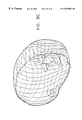
- FIGS. 8A, 8 B, 8 C and 8 D are pictorial illustrations showing the progressive shrinking of an imaging balloon about an image of the head of a fetus
- FIGS. 9A and 9B together are a flowchart illustrating a three-dimensional filtering operation performed in accordance with a preferred embodiment of the present invention on an original volume image
- FIG. 10 is an illustration useful in understanding the filtering operation illustrated in FIGS. 9A and 9B;
- FIG. 11 is a flow chart illustrating 3-D image segmentation step of the operation of FIG. 3A in accordance with a preferred embodiment of the present invention.
- FIG. 12 is a flow chart illustrating a region of interest defining step of the operation of FIG. 11 in accordance with a preferred embodiment of the present invention
- FIGS. 13A and 13B together are a flowchart illustrating a two-dimensional filtering operation performed in accordance with a preferred embodiment of the present invention on an original volume image
- FIGS. 14A and 14B together are a flow chart illustrating one part of an optimal boundary defining step of the operation of FIG. 11 in accordance with a preferred embodiment of the present invention.
- FIG. 15 is a flow chart illustrating another part of the optimal boundary defining step of the operation of FIG. 11 in accordance with a preferred embodiment of the present invention.
- FIG. 16 is an illustration useful in understanding the flowchart of FIG. 12;
- FIG. 17 is an illustration useful in understanding the flowchart of FIGS. 13A and 13B;
- FIGS. 18A and 18B are illustrations useful in understanding the flowchart of FIG. 14.
- FIG. 19 is an illustration useful in understanding the flowchart of FIG. 15 .
- FIG. 1 is a simplified block diagram illustration of a fetal weight determination system constructed and operative in accordance with a preferred embodiment of the present invention.
- the fetal weight determination system of an embodiment of the present invention preferably comprises a 2-D or a volume imager 110 .
- Imager 110 may be of any suitable type and may employ any suitable technology, such as, for example, ultrasound imaging. It is also possible that magnetic resonance imaging (MRI) could be employed.
- ultrasound volume imagers and imaging software include:
- Imaging software available from A1 Alpha Space, Inc, of Websites, Calif., U.S.A. and from Echotech 3-D of Hallbergmoos, Germany;
- HDI1500 commercially available from ATL—Advanced Technology Laboratories, Bothell, Wash., U.S.A.;
- Echo-Scan, Echo-View and Compact3-D commercially available from TomTec Imaging Systems GmbH of Unterschleissheim, Germany;
- NetralVUS commercially available from ScImage, Inc. of Los Altos, Calif. 94022, U.S.A.;
- VoxarLib commercially available from Voxar Ltd. of Edinburgh, UK;
- volume imagers operate on a slice-by-slice basis. It is anticipated, however, that volume imagers which do not operate on a slice-by-slice basis will become available in the future and will also be useful in the present invention.
- image data from imager 110 is supplied to an image processing based computerized segmenter, preferably an edge detection based segmenter 112 preferably embodied in a workstation including a display and a suitable user input device (not shown).
- segmenter 112 receives the output of imager 110 and enables a workstation operator, using that output, to readily locate and isolate a fetal image.
- Segmenter 112 is operative in a computer-assisted manner, preferably under the control of the operator, to differentiate between various body parts and tissues and to distinguish the fetus from its environment, such as for example, from the amniotic fluid in which it resides and the surrounding placenta and uterus.
- modified or annotated image data from segmenter 112 is employed by a measurement tool 114 to provide information relating to overall fetal volume, volumes of body parts of the fetus, areas of various cross sections of the fetus, sizes of various bones and body parts of the fetus.
- This information is supplied to a fetal weight calculator 116 , which may also receive inputs from an archive 118 .
- Archive 118 may include information relating to at least one of measurement data derived from measurements of a multiplicity of other fetuses, correlations between said measurement data and birth weights, and data from earlier measurements of said same fetus and combinations of the foregoing.
- the fetal weight calculator 116 is operative to employ inputs received from measurement tool 114 and archive 118 in one or more operational modes to produce an output indication of estimated fetal weight.
- the output indication is supplied to an output device 120 , such as a computerized medical archive, local or remote display, printer, annunciator, recorder or a combination of the foregoing with any other functionality.
- measurement tool 114 may be entirely computer controlled and operated.
- edge detection based segmenter 112 may be integrated in the same computer platform which serves to control the operation of imager 110 .
- FIG. 2 is a simplified flow chart illustrating operation of the system of FIG. 1 in accordance with a preferred embodiment of the present invention.
- the fetal weight determination methodology of an embodiment of the present invention preferably employs a 2-D or volume imager, preferably imager 110 (FIG. 1 ), to acquire an image of all or part of the fetus.
- a 2-D or volume imager preferably imager 110 (FIG. 1 )
- the acquired image data is segmented by an edge detection based segmenter, preferably segmenter 112 (FIG. 1 ).
- the segmentation functionality is operative in a computer-assisted manner, preferably under the control of the operator, to differentiate between various body parts and tissues and to distinguish the fetus from its environment, such as for example, from the amniotic fluid in which it resides and the surrounding placenta and uterus.
- the output of the segmenter is employed by a measurement tool, preferably measurement tool 114 (FIG. 1) to provide information relating to overall fetal volume and preferably also to provide information relating to volumes of body parts of the fetus, areas of various cross sections of the fetus, sizes of various bones and body parts of the fetus.
- a measurement tool preferably measurement tool 114 (FIG. 1) to provide information relating to overall fetal volume and preferably also to provide information relating to volumes of body parts of the fetus, areas of various cross sections of the fetus, sizes of various bones and body parts of the fetus.
- a fetal weight calculator preferably fetal weight calculator 116 (FIG. 1) provides an estimate of fetal weight and employs for this purpose the measurements carried out by the measurement tool as well as preferably also archived inputs, such as, for example, information relating to at least one of measurement data derived from measurements of a multiplicity of other fetuses, correlations between said measurement data and birth weights, and data from earlier measurements of said same fetus.
- FIGS. 3A & 3B are flow charts each illustrating an alternative embodiment of an initial part of the operation shown in FIG. 2 including image acquisition and segmentation.
- a volume image of a fetus may be obtained either as a volume image directly from a volume imager or by construction from a multiplicity of slices produced by a 2-D imager.
- the volume image may be segmented either by 3-D segmentation or by slice-by-slice segmentation. In both cases segmented volume image data is provided.
- FIG. 3B illustrates an alternative wherein 2-D images are acquired and 2-D segmentation is performed thereon, producing segmented 2-D image data. If desired, the segmented 2-D image data may be used to construct segmented volume image data.
- FIG. 4 is a pictorial illustration showing some of the features of the measurement tool 114 (FIG. 1 ).
- the measurement tool 114 is operative to measure features of the fetus along selected planes, such as plane 124 .
- plane 124 is aligned with a femur 126 of the fetus, the length of which it is sought to measure.
- FIGS. 5A & 5B are flow charts each illustrating an alternative embodiment of a final part of the operation shown in FIG. 2, including the fetal weight calculation.
- the fetal weight calculation may be carried out based on measurements of the entire fetal body or only parts thereof. Where only parts of the fetal body are measured, such as only the torso and the head, suitable extrapolations may be carried out in order to enable a full body weight determination to be made. In such a case either a whole body density or densities of the measured parts of the fetal body may be used.
- fetal weight determined as aforesaid.
- known correlations between fetal weight and one or more of femur length, crown-rump length, abdominal circumference and biparietal diameter may be employed to normalize or modify the fetal weight determined from the measurements.
- FIG. 5B it is seen that whereas in the functionality of FIG. 5A, the entire fetal body or body parts are treated as units having uniform density for the purposes of weight determination, in FIG. 5B, measurements of various components of the fetal body which have substantially different densities, such as tissue, bone and fluid, are utilized to provide separate weight determinations which are added to arrive at a total fetal body weight.
- measurements of various components of the fetal body which have substantially different densities such as tissue, bone and fluid, are utilized to provide separate weight determinations which are added to arrive at a total fetal body weight.
- statistically derived or other archived information may be used to normalize or otherwise modify the fetal weight determined as aforesaid.
- FIG. 6 is a flow chart illustrating the 3-D segmentation step of the operation of FIG. 3A in accordance with a preferred embodiment of the present invention.
- a 3-D image which may have associated therewith initial markings distinguishing between portions of the image which are of interest and portions of the image which it is desired to discard, is subjected to surface edge detection based segmentation 160 which preferably initially performs surface edge enhancement on the received 3-D image.
- a balloon which is centered on a region of the image which is of interest.
- the balloon may be defined with the assistance of operator generated markings on the 3-D image, but does not require such markings.
- the balloon may be subsequently automatically expanded or shrunk until its boundaries lie on or near enhanced edges of the 3-D image or on operator input markings, which may be supplied in the course of 3-D segmentation and not only prior thereto.
- the final balloon configuration defines one or more surface boundary.
- An example of progressive shrinkage of the balloon about a fetal head is illustrated in FIGS. 8A, 8 B, 8 C and 8 D. Shrinkage of the balloon is known from the following prior art publications, the disclosures of which are hereby incorporated by reference:
- the resultant one or more surface boundary is superimposed on the 3-D image.
- An operator may carry out a visual confirmation check to satisfy himself that the indicated boundaries are indeed correct. If so, a closed surface boundary superimposed on the 3-D image is output.
- FIG. 7 is a flow chart illustrating a surface edge enhancement step of the operation of FIG. 6 in accordance with a preferred embodiment of the present invention.
- the volume image is preferably blurred using a 3-D filter, such as a 3-D Gaussian filter. Thereafter, a 3-D median filter is preferably applied to the blurred volume image.
- a 3-D filter such as a 3-D Gaussian filter.
- a plane enhancement filter is applied to the pre-processed image, thus producing a surface edge enhanced volume image output.
- FIGS. 9A and 9B are a flowchart illustrating a three-dimensional filtering operation performed in accordance with a preferred embodiment of the present invention on an original volume image.
- a filtering operation is preferably employed as part of the step of performing surface edge enhancement of a 3-D image forming part of edge detection based segmentation 160 , as shown in FIG. 6 and corresponds to the step in FIG. 7 identified as “APPLY PLANE ENHANCEMENT FILTER”.
- FIG. 10 is an illustration useful in understanding the filtering operation illustrated in FIGS. 9A and 9B;
- FIGS. 9A and 9B taken together with FIG. 10, describe steps of a filtering operation which is performed on the volume image received from imager 110 (FIG. 1) in accordance with a preferred embodiment of the present invention.
- the detailed flowchart of FIGS. 9A and 9B describes a plane enhancement operator.
- the plane enhancement operator is an extension to three dimensions of edge or ridge enhancement operators in 2 dimensions described hereinbelow with reference to FIGS. 13A & 13B as well as FIG. 17 .
- the plane enhancement operator operates upon a volumetric image and provides a grey-level volumetric image output in which the edges or ridges appear as enhanced surfaces in 3 dimensions. Stated more generally, the plane enhancement operator provides a volumetric image representation of the intensity of the surface edge property at each image voxel.
- FIG. 10 is an illustration of the plane enhancement operator whose functionality is detailed in FIGS. 9A & 9B. For the sake of conciseness, in view of the detailed nature of the steps of the operation indicated in FIGS. 9A and 9B with reference to FIG. 10, a further textual explanation of these steps is believed to be unnecessary and thus is not provided.
- FIG. 11 is a flow chart illustrating a slice-by-slice image segmentation step of the operation of FIG. 3A in accordance with a preferred embodiment of the present invention.
- a 2-D image which may be sliced from a volume image, is selected by the system or by an operator and is initially operated on by the segmenter using an operator input which applies initial markings, such as boundary markings, to various portions of the 2-D image to distinguish between portions of the image which are of interest and portions of the image which it is desired to discard.
- 2-D segmentation is carried out using edge detection techniques in accordance with an algorithm which is described hereinbelow.
- the segmenter provides an output which may be stored while additional 2-D image slices are segmented as described hereinabove.
- the output and/or other characteristics of at least one preceding 2-D image are used as initial markings or in any other suitable manner for determining or partially determining the boundary. It is appreciated that the image may include more than one boundary.
- the segmentation output defines a closed boundary or boundaries distinguishing portions of the image which are of interest and portions of the image which it is desired to discard.
- the 2-D segmentation step shown in FIG. 11 preferably incorporates the following steps:
- Initial markings or the preceding boundary are superimposed on the image and a visual check of the boundary may then be carried out. If the boundary appears to need correction and a manual correction is called for, a manual correction is carried out. If, however the boundary does not appear to need correction, it is preferably stored. If the slice being segmented is the last 2-D image slice to be segment in the 3-D image, the volume having the output boundary or boundaries superimposed thereover is output. If the slice being segmented is not the last 2-D slice to be segmented in the 3-D image, a further 2-D slice is selected. The previous boundary is preferably defined as an initial boundary for the further slice.
- a manual correction module applies a manual correction to the boundary or boundaries superimposed on the image. If manual correction is not called for, computerized correction is typically effected by edge detection based segmentation circuitry 190 .
- edge detection based segmentation circuitry 190 may be summarized as follows: The boundary or boundaries initially superimposed on the image are supplied to circuitry 190 separately from the image and are broadened in order to define a strip-shaped region or regions of interest (ROI). Edge enhancement is performed on the image, preferably, but not necessarily, within the ROI. As seen in FIGS. 18A & 18B, referred to hereinbelow, a multiple vertex geometrical construction is provided within the region of interest and includes a multiplicity of vertices interconnected by line segments, wherein each line segment is assigned a weight. As described in greater detail hereinbelow, an optimal boundary is constructed from the line segments. The optimal boundary is then superimposed onto the image.
- ROI strip-shaped region or regions of interest
- FIG. 12 is a flow chart illustrating a strip shaped region of interest defining step of the operation of FIG. 11 in accordance with a preferred embodiment of the present invention and to FIG. 16 which shows such a region of interest.
- the initial marking or boundary is received and any closed loops along the initial marking or boundary are deleted.
- a strip-shaped region of interest is defined about each initial marking or boundary, for example by employing a convolution having filled circles of constant pixel value as a convolution kernel. The circles need not all have the same diameter.
- a thresholding function is then applied to discard pixels located exteriorly to the region of interest. The thus-corrected initial marking or boundary is then output together with the strip-shaped region of interest.
- FIGS. 13A and 13B are a flowchart illustrating a two-dimensional edge enhancement filtering operation performed in accordance with a preferred embodiment of the present invention on a slice of the original volume image and to FIG. 17, which is an illustration useful in understanding the flowchart of FIGS. 13A and 13B. It is appreciated that the operation of FIGS. 13A and 13B provides a grey level edge enhanced image. Stated more generally, the operation provides an image representation of the intensity of the edge property at each image pixel.
- FIGS. 13A, 13 B and 17 The operation illustrated in FIGS. 13A, 13 B and 17 is carried out at each pixel location in each slice of the volume image and searches for a candidate edge segment at every such pixel location, preferably by searching for the direction of a candidate edge segment.
- a further textual explanation of these steps is believed to be unnecessary and thus is not provided.
- FIGS. 14A and 14B are a flow chart illustrating one part of an optimal boundary defining step of the operation of FIG. 11 in accordance with a preferred embodiment of the present invention which includes providing a multiple vertex geometrical construction within the region of interest having a multiplicity of vertices interconnected by line segments, wherein each line segment is assigned a weight.
- FIGS. 18A and 18B are useful in the understanding of the flow chart of FIGS. 14A & 14B.
- the functionality of FIGS. 14A & 14B provides information for use in defining a closed boundary within the region of interest.
- the closed boundary is determined at each point therealong inter alia based on the following characteristics: proximity to an initial marking or a boundary already determined for an adjacent or other slice, the degree of similarity in direction to the initial marking or previously determined boundary and the degree of overlap with the initial marking or previously determined boundary.
- proximity to an initial marking or a boundary already determined for an adjacent or other slice the degree of similarity in direction to the initial marking or previously determined boundary and the degree of overlap with the initial marking or previously determined boundary.
- the degree of similarity in direction to the initial marking or previously determined boundary may be employed in subsequently determining the boundary for the current slice.
- FIG. 15 is a flow chart illustrating a further part of the optimal boundary defining step of the operation of FIG. 11 in accordance with a preferred embodiment of the present invention which provides an optimal boundary by employing dynamic programming based on the operations described hereinabove with reference to FIGS. 14A, 14 B, 18 A and 18 B.
- FIG. 19 is an illustration useful in understanding the flowchart of FIG. 15 .
Abstract
Description
Claims (30)
Priority Applications (4)
| Application Number | Priority Date | Filing Date | Title |
|---|---|---|---|
| US09/351,252 US6575907B1 (en) | 1999-07-12 | 1999-07-12 | Determination of fetal weight in utero |
| PCT/IL2000/000411 WO2001004598A2 (en) | 1999-07-12 | 2000-07-12 | Determination of fetal weight in utero |
| CA002343331A CA2343331A1 (en) | 1999-07-12 | 2000-07-12 | Determination of fetal weight in utero |
| AU58427/00A AU5842700A (en) | 1999-07-12 | 2000-07-12 | Determination of fetal weight in utero |
Applications Claiming Priority (1)
| Application Number | Priority Date | Filing Date | Title |
|---|---|---|---|
| US09/351,252 US6575907B1 (en) | 1999-07-12 | 1999-07-12 | Determination of fetal weight in utero |
Publications (1)
| Publication Number | Publication Date |
|---|---|
| US6575907B1 true US6575907B1 (en) | 2003-06-10 |
Family
ID=23380214
Family Applications (1)
| Application Number | Title | Priority Date | Filing Date |
|---|---|---|---|
| US09/351,252 Expired - Lifetime US6575907B1 (en) | 1999-07-12 | 1999-07-12 | Determination of fetal weight in utero |
Country Status (4)
| Country | Link |
|---|---|
| US (1) | US6575907B1 (en) |
| AU (1) | AU5842700A (en) |
| CA (1) | CA2343331A1 (en) |
| WO (1) | WO2001004598A2 (en) |
Cited By (23)
| Publication number | Priority date | Publication date | Assignee | Title |
|---|---|---|---|---|
| US20050240104A1 (en) * | 2004-04-01 | 2005-10-27 | Medison Co., Ltd. | Apparatus and method for forming 3D ultrasound image |
| WO2006031526A2 (en) * | 2004-09-09 | 2006-03-23 | Diagnostic Ultrasound Corporation | Systems and methods for ultrasound imaging using an inertial reference unit |
| US20060235301A1 (en) * | 2002-06-07 | 2006-10-19 | Vikram Chalana | 3D ultrasound-based instrument for non-invasive measurement of amniotic fluid volume |
| EP1743581A1 (en) * | 2005-07-11 | 2007-01-17 | Esaote S.p.A. | Method and system for foetal weight evaluation |
| US20080114243A1 (en) * | 2006-11-10 | 2008-05-15 | Kabushiki Kaisha Toshiba | Ultrasonic diagnostic apparatus, ultrasonic diagnostic method, and image processing program for ultrasonic diagnostic apparatus |
| US7378846B1 (en) * | 2004-06-29 | 2008-05-27 | Fonar Corporation | Magnetic resonance imaging method and apparatus for scanning a child |
| US20080141380A1 (en) * | 2006-12-12 | 2008-06-12 | Kabushiki Kaisha Toshiba | Software component, software component management method, and software component management system |
| US7399278B1 (en) * | 2003-05-05 | 2008-07-15 | Los Angeles Biomedical Research Institute At Harbor-Ucla Medical Center | Method and system for measuring amniotic fluid volume and/or assessing fetal weight |
| US20100082147A1 (en) * | 2007-04-19 | 2010-04-01 | Susanne Damvig | Method for the manufacturing of a reproduction of an encapsulated head of a foetus and objects obtained by the method |
| US20100198075A1 (en) * | 2002-08-09 | 2010-08-05 | Verathon Inc. | Instantaneous ultrasonic echo measurement of bladder volume with a limited number of ultrasound beams |
| US7819806B2 (en) | 2002-06-07 | 2010-10-26 | Verathon Inc. | System and method to identify and measure organ wall boundaries |
| US20110125016A1 (en) * | 2009-11-25 | 2011-05-26 | Siemens Medical Solutions Usa, Inc. | Fetal rendering in medical diagnostic ultrasound |
| US8133181B2 (en) | 2007-05-16 | 2012-03-13 | Verathon Inc. | Device, system and method to measure abdominal aortic aneurysm diameter |
| US8167803B2 (en) | 2007-05-16 | 2012-05-01 | Verathon Inc. | System and method for bladder detection using harmonic imaging |
| US8221322B2 (en) | 2002-06-07 | 2012-07-17 | Verathon Inc. | Systems and methods to improve clarity in ultrasound images |
| US8221321B2 (en) | 2002-06-07 | 2012-07-17 | Verathon Inc. | Systems and methods for quantification and classification of fluids in human cavities in ultrasound images |
| US20120232394A1 (en) * | 2010-09-30 | 2012-09-13 | Bunpei Toji | Ultrasound diagnostic apparatus |
| US20140270395A1 (en) * | 2013-03-15 | 2014-09-18 | Propel lP | Methods and apparatus for determining information about objects from object images |
| EP2807977A1 (en) * | 2013-05-31 | 2014-12-03 | Samsung Medison Co., Ltd. | Ultrasound diagnosis method and aparatus using three-dimensional volume data |
| US20160058422A1 (en) * | 2014-09-01 | 2016-03-03 | Samsung Medison Co., Ltd. | Ultrasound diagnosis apparatus, ultrasound diagnosis method performed by the ultrasound diagnosis apparatus, and computer-readable storage medium having the ultrasound diagnosis method recorded thereon |
| EP3593728A1 (en) * | 2018-07-10 | 2020-01-15 | Koninklijke Philips N.V. | Methods and systems for performing fetal weight estimations |
| CN110974302A (en) * | 2019-10-21 | 2020-04-10 | 李胜利 | Automatic detection method and system for fetal head volume in ultrasonic image |
| EP4223227A1 (en) * | 2022-02-03 | 2023-08-09 | Koninklijke Philips N.V. | A method and system for performing fetal weight estimations |
Families Citing this family (1)
| Publication number | Priority date | Publication date | Assignee | Title |
|---|---|---|---|---|
| CZ302930B6 (en) * | 2003-12-08 | 2012-01-18 | Continuous weighing method of moving vehicle units and/or optimization of their further drive |
Citations (7)
| Publication number | Priority date | Publication date | Assignee | Title |
|---|---|---|---|---|
| US4341120A (en) * | 1979-11-09 | 1982-07-27 | Diasonics Cardio/Imaging, Inc. | Ultrasonic volume measuring system |
| US5239591A (en) | 1991-07-03 | 1993-08-24 | U.S. Philips Corp. | Contour extraction in multi-phase, multi-slice cardiac mri studies by propagation of seed contours between images |
| US5588435A (en) | 1995-11-22 | 1996-12-31 | Siemens Medical Systems, Inc. | System and method for automatic measurement of body structures |
| US5605155A (en) | 1996-03-29 | 1997-02-25 | University Of Washington | Ultrasound system for automatically measuring fetal head size |
| US5608849A (en) * | 1991-08-27 | 1997-03-04 | King, Jr.; Donald | Method of visual guidance for positioning images or data in three-dimensional space |
| US5655535A (en) | 1996-03-29 | 1997-08-12 | Siemens Medical Systems, Inc. | 3-Dimensional compound ultrasound field of view |
| US5795296A (en) | 1996-03-29 | 1998-08-18 | University Of Washington | Pipeline process for automatically measuring object boundary from ultrasound image samples |
-
1999
- 1999-07-12 US US09/351,252 patent/US6575907B1/en not_active Expired - Lifetime
-
2000
- 2000-07-12 AU AU58427/00A patent/AU5842700A/en not_active Abandoned
- 2000-07-12 WO PCT/IL2000/000411 patent/WO2001004598A2/en active Application Filing
- 2000-07-12 CA CA002343331A patent/CA2343331A1/en not_active Abandoned
Patent Citations (7)
| Publication number | Priority date | Publication date | Assignee | Title |
|---|---|---|---|---|
| US4341120A (en) * | 1979-11-09 | 1982-07-27 | Diasonics Cardio/Imaging, Inc. | Ultrasonic volume measuring system |
| US5239591A (en) | 1991-07-03 | 1993-08-24 | U.S. Philips Corp. | Contour extraction in multi-phase, multi-slice cardiac mri studies by propagation of seed contours between images |
| US5608849A (en) * | 1991-08-27 | 1997-03-04 | King, Jr.; Donald | Method of visual guidance for positioning images or data in three-dimensional space |
| US5588435A (en) | 1995-11-22 | 1996-12-31 | Siemens Medical Systems, Inc. | System and method for automatic measurement of body structures |
| US5605155A (en) | 1996-03-29 | 1997-02-25 | University Of Washington | Ultrasound system for automatically measuring fetal head size |
| US5655535A (en) | 1996-03-29 | 1997-08-12 | Siemens Medical Systems, Inc. | 3-Dimensional compound ultrasound field of view |
| US5795296A (en) | 1996-03-29 | 1998-08-18 | University Of Washington | Pipeline process for automatically measuring object boundary from ultrasound image samples |
Non-Patent Citations (33)
| Title |
|---|
| "Finite-Element Methods for Active Contour Models and Balloons for 2-D and 3-D Images", L.D. Cohen and I. Cohen, IEEE Transactions on Pattern Analysis and Machine Intelligence, vol. 5 15, No. 11 (1993). |
| "On Active Contour Models and Balloons", L.D. Cohen, CVGIP: Image Understanding, vol. 53, No. 2, pp. 211-218 (1991). |
| "Snakes, Active Contours, and Deformable Models", http://www.wpi.edu/~dima/ummed/presentation/index.html. |
| "USCD Radiologists are Working on a New Ultrasound Technology that's Guaranteed to Produce Much Clearer Images in Three Dimensions", K. Deely; USCD Perspectives, Spring 1999. |
| "Snakes, Active Contours, and Deformable Models", http://www.wpi.edu/˜dima/ummed/presentation/index.html. |
| Dudley et al., "A new method for fetal weight estimation using real-time ultrasound", British Journal of Obstetrics and Gynaecology, vol. 94, pp. 11-114. Feb. 1987.* * |
| Liang et al., "Predicting birth weight by fetal upper-arm volume with use of three-dimensional ultrasonography", Am. J. Obstet Gynecol, vol. 177:632-8. Sep. 1997.* * |
| Product details-3-D Ultrasound-Acquisition Methods Details, Life Imaging Systems Inc., London, Ontario, Canada. |
| Product details—3-D Ultrasound—Acquisition Methods Details, Life Imaging Systems Inc., London, Ontario, Canada. |
| Product details-3-Scape, commercially available from Siemens AG; Erlangen, Germany. |
| Product details—3-Scape, commercially available from Siemens AG; Erlangen, Germany. |
| Product details-EchoScan, Echo-View and Compact 3-D commercially avaiable from TomTec Imaging Systems; GmbH, Unterschleissheim, Germany. |
| Product details—EchoScan, Echo-View and Compact 3-D commercially avaiable from TomTec Imaging Systems; GmbH, Unterschleissheim, Germany. |
| Product details-HDI1500, commercially available from Advanced Technology Laboratories; Bothell, WA, USA. |
| Product details—HDI1500, commercially available from Advanced Technology Laboratories; Bothell, WA, USA. |
| Product details-Imaging software available from A1 Alpha Space Inc; Laguna Hills, CA, USA. |
| Product details—Imaging software available from A1 Alpha Space Inc; Laguna Hills, CA, USA. |
| Product details-InViVo-ScanNT; Fraunhofer Institut fuer Graphische Datenverarbeitung IGD; Darmstadt, Germany. |
| Product details—InViVo-ScanNT; Fraunhofer Institut fuer Graphische Datenverarbeitung IGD; Darmstadt, Germany. |
| Product details-L3-Di, commercially available from Life Imaging Systems; London, Ontario, Canada. |
| Product details—L3-Di, commercially available from Life Imaging Systems; London, Ontario, Canada. |
| Product details-Logic 700 MR, commerically available from GE Ultrasound. |
| Product details—Logic 700 MR, commerically available from GE Ultrasound. |
| Product details-NetralVUS, commercially available from ScImage Inc.; Los Altos, CA 94022, USA. |
| Product details—NetralVUS, commercially available from ScImage Inc.; Los Altos, CA 94022, USA. |
| Product details-Vitrea, commercially available from Vital Images Inc.; Minneapolis, MN, USA. |
| Product details—Vitrea, commercially available from Vital Images Inc.; Minneapolis, MN, USA. |
| Product details-Voluson 530D, commercially available from Medison America; Pleasanton, CA, USA. |
| Product details—Voluson 530D, commercially available from Medison America; Pleasanton, CA, USA. |
| Product details-VoxarLib, commercially available from Voxar, Ldt.; Edinburgh, UK. |
| Product details—VoxarLib, commercially available from Voxar, Ldt.; Edinburgh, UK. |
| Shinozuka et al., "Fetal weight estimation by ultrasound measurement", Am. J. Obstet Gynecol, vol. 157:11405, 1987. * |
| Thompson et al., "Estimation of Volume and Weight of the Perinate: Relationship to Morphometric Measurement by Ultrasonography", J Ultrasound Med 2:113-116. Mar. 1983.* * |
Cited By (42)
| Publication number | Priority date | Publication date | Assignee | Title |
|---|---|---|---|---|
| US7744534B2 (en) * | 2002-06-07 | 2010-06-29 | Verathon Inc. | 3D ultrasound-based instrument for non-invasive measurement of amniotic fluid volume |
| US20060235301A1 (en) * | 2002-06-07 | 2006-10-19 | Vikram Chalana | 3D ultrasound-based instrument for non-invasive measurement of amniotic fluid volume |
| US8221321B2 (en) | 2002-06-07 | 2012-07-17 | Verathon Inc. | Systems and methods for quantification and classification of fluids in human cavities in ultrasound images |
| US8221322B2 (en) | 2002-06-07 | 2012-07-17 | Verathon Inc. | Systems and methods to improve clarity in ultrasound images |
| US7819806B2 (en) | 2002-06-07 | 2010-10-26 | Verathon Inc. | System and method to identify and measure organ wall boundaries |
| US9993225B2 (en) | 2002-08-09 | 2018-06-12 | Verathon Inc. | Instantaneous ultrasonic echo measurement of bladder volume with a limited number of ultrasound beams |
| US8308644B2 (en) | 2002-08-09 | 2012-11-13 | Verathon Inc. | Instantaneous ultrasonic measurement of bladder volume |
| US20100198075A1 (en) * | 2002-08-09 | 2010-08-05 | Verathon Inc. | Instantaneous ultrasonic echo measurement of bladder volume with a limited number of ultrasound beams |
| US7399278B1 (en) * | 2003-05-05 | 2008-07-15 | Los Angeles Biomedical Research Institute At Harbor-Ucla Medical Center | Method and system for measuring amniotic fluid volume and/or assessing fetal weight |
| US20050240104A1 (en) * | 2004-04-01 | 2005-10-27 | Medison Co., Ltd. | Apparatus and method for forming 3D ultrasound image |
| US7507204B2 (en) * | 2004-04-01 | 2009-03-24 | Medison Co., Ltd. | Apparatus and method for forming 3D ultrasound image |
| US7378846B1 (en) * | 2004-06-29 | 2008-05-27 | Fonar Corporation | Magnetic resonance imaging method and apparatus for scanning a child |
| WO2006031526A2 (en) * | 2004-09-09 | 2006-03-23 | Diagnostic Ultrasound Corporation | Systems and methods for ultrasound imaging using an inertial reference unit |
| WO2006031526A3 (en) * | 2004-09-09 | 2007-03-15 | Diagnostic Ultrasound Corp | Systems and methods for ultrasound imaging using an inertial reference unit |
| US20070038093A1 (en) * | 2005-07-11 | 2007-02-15 | Felice Petraglia | Method and system for fetal weight evaluation |
| US8012091B2 (en) | 2005-07-11 | 2011-09-06 | Esoate S.P.A. | Method and system for fetal weight estimation |
| EP1743581A1 (en) * | 2005-07-11 | 2007-01-17 | Esaote S.p.A. | Method and system for foetal weight evaluation |
| US20080114243A1 (en) * | 2006-11-10 | 2008-05-15 | Kabushiki Kaisha Toshiba | Ultrasonic diagnostic apparatus, ultrasonic diagnostic method, and image processing program for ultrasonic diagnostic apparatus |
| JP2008136860A (en) * | 2006-11-10 | 2008-06-19 | Toshiba Corp | Ultrasonic diagnostic apparatus and image processing program for it |
| US20080141380A1 (en) * | 2006-12-12 | 2008-06-12 | Kabushiki Kaisha Toshiba | Software component, software component management method, and software component management system |
| US8566949B2 (en) | 2006-12-12 | 2013-10-22 | Kabushiki Kaisha Toshiba | Software component, software component management method, and software component management system |
| US20100082147A1 (en) * | 2007-04-19 | 2010-04-01 | Susanne Damvig | Method for the manufacturing of a reproduction of an encapsulated head of a foetus and objects obtained by the method |
| US8352059B2 (en) * | 2007-04-19 | 2013-01-08 | Damvig Develop Future Aps | Method for the manufacturing of a reproduction of an encapsulated head of a foetus and objects obtained by the method |
| US8133181B2 (en) | 2007-05-16 | 2012-03-13 | Verathon Inc. | Device, system and method to measure abdominal aortic aneurysm diameter |
| US8167803B2 (en) | 2007-05-16 | 2012-05-01 | Verathon Inc. | System and method for bladder detection using harmonic imaging |
| US20110125016A1 (en) * | 2009-11-25 | 2011-05-26 | Siemens Medical Solutions Usa, Inc. | Fetal rendering in medical diagnostic ultrasound |
| EP2623033A1 (en) * | 2010-09-30 | 2013-08-07 | Panasonic Corporation | Ultrasound diagnostic equipment |
| EP2623033A4 (en) * | 2010-09-30 | 2014-07-30 | Panasonic Corp | Ultrasound diagnostic equipment |
| US20120232394A1 (en) * | 2010-09-30 | 2012-09-13 | Bunpei Toji | Ultrasound diagnostic apparatus |
| US20140270395A1 (en) * | 2013-03-15 | 2014-09-18 | Propel lP | Methods and apparatus for determining information about objects from object images |
| EP2807977A1 (en) * | 2013-05-31 | 2014-12-03 | Samsung Medison Co., Ltd. | Ultrasound diagnosis method and aparatus using three-dimensional volume data |
| KR20140141384A (en) * | 2013-05-31 | 2014-12-10 | 삼성메디슨 주식회사 | Method and apparatus for ultrasound diagnosis using 3d volume data |
| KR102150959B1 (en) | 2013-05-31 | 2020-09-02 | 삼성메디슨 주식회사 | Method and apparatus for ultrasound diagnosis using 3d volume data |
| US10470744B2 (en) * | 2014-09-01 | 2019-11-12 | Samsung Medison Co., Ltd. | Ultrasound diagnosis apparatus, ultrasound diagnosis method performed by the ultrasound diagnosis apparatus, and computer-readable storage medium having the ultrasound diagnosis method recorded thereon |
| US20160058422A1 (en) * | 2014-09-01 | 2016-03-03 | Samsung Medison Co., Ltd. | Ultrasound diagnosis apparatus, ultrasound diagnosis method performed by the ultrasound diagnosis apparatus, and computer-readable storage medium having the ultrasound diagnosis method recorded thereon |
| EP3593728A1 (en) * | 2018-07-10 | 2020-01-15 | Koninklijke Philips N.V. | Methods and systems for performing fetal weight estimations |
| WO2020011569A1 (en) | 2018-07-10 | 2020-01-16 | Koninklijke Philips N.V. | Methods and systems for performing fetal weight estimations |
| CN112672695A (en) * | 2018-07-10 | 2021-04-16 | 皇家飞利浦有限公司 | Method and system for performing fetal weight estimation |
| US20210298717A1 (en) * | 2018-07-10 | 2021-09-30 | Koninklijke Philips N.V. | Methods and systems for performing fetal weight estimations |
| CN110974302A (en) * | 2019-10-21 | 2020-04-10 | 李胜利 | Automatic detection method and system for fetal head volume in ultrasonic image |
| EP4223227A1 (en) * | 2022-02-03 | 2023-08-09 | Koninklijke Philips N.V. | A method and system for performing fetal weight estimations |
| WO2023148160A1 (en) | 2022-02-03 | 2023-08-10 | Koninklijke Philips N.V. | Method and system for performing fetal weight estimations |
Also Published As
| Publication number | Publication date |
|---|---|
| AU5842700A (en) | 2001-01-30 |
| WO2001004598A2 (en) | 2001-01-18 |
| CA2343331A1 (en) | 2001-01-18 |
| WO2001004598A3 (en) | 2001-07-12 |
Similar Documents
| Publication | Publication Date | Title |
|---|---|---|
| US6575907B1 (en) | Determination of fetal weight in utero | |
| US6375616B1 (en) | Automatic fetal weight determination | |
| US6251072B1 (en) | Semi-automated segmentation method for 3-dimensional ultrasound | |
| US7356367B2 (en) | Computer aided treatment planning and visualization with image registration and fusion | |
| US7744534B2 (en) | 3D ultrasound-based instrument for non-invasive measurement of amniotic fluid volume | |
| US7520857B2 (en) | 3D ultrasound-based instrument for non-invasive measurement of amniotic fluid volume | |
| EP1538986B1 (en) | 3d ultrasound-based instrument for non-invasive measurement of fluid-filled and non fluid-filled structures | |
| CN110325119B (en) | Ovarian follicle count and size determination | |
| US7041059B2 (en) | 3D ultrasound-based instrument for non-invasive measurement of amniotic fluid volume | |
| EP1319217B1 (en) | Technique for manipulating medical images | |
| US7611466B2 (en) | Ultrasound system and method for measuring bladder wall thickness and mass | |
| De Odorico et al. | Normal splenic volumes estimated using three‐dimensional ultrasonography. | |
| Zheng et al. | Reduction of breast biopsies with a modified self-organizing map | |
| US11696740B2 (en) | Method and system for defining cut lines to generate a 3D fetal representation | |
| US6434260B1 (en) | Facial imaging in utero | |
| Lee | 3D fetal ultrasonography | |
| Treece | Volume measurement and surface visualisation in sequential freehand 3D ultrasound | |
| JP2895414B2 (en) | Ultrasonic volume calculator | |
| Gill et al. | Development and evaluation of a semiautomatic 3D segmentation technique of the carotid arteries from 3D ultrasound images | |
| Beksaç et al. | An intelligent diagnostic system for the assessment of gestational age based on ultrasonic fetal head measurements | |
| Hughes et al. | The accuracy of a new system for estimating organ volume using ultrasound | |
| Lu | Hough transforms for shape identification and applications in medical image processing | |
| Olstad et al. | 3d transvaginal ultrasound imaging for identification of endometrial abnormality | |
| Wu et al. | A novel algorithm for computer-assisted measurement of cervical length from transvaginal ultrasound images | |
| Gomes | Advanced computational methodologies for fetus face |
Legal Events
| Date | Code | Title | Description |
|---|---|---|---|
| AS | Assignment |
Owner name: BIOMEDICOM, CREATIVE BIOMEDICAL COMPUTING LTD., IS Free format text: ASSIGNMENT OF ASSIGNORS INTEREST;ASSIGNORS:SOFERMAN, ZIV;BERMAN, MICHAEL;REEL/FRAME:010109/0800 Effective date: 19990708 |
|
| STCF | Information on status: patent grant |
Free format text: PATENTED CASE |
|
| FEPP | Fee payment procedure |
Free format text: PAYOR NUMBER ASSIGNED (ORIGINAL EVENT CODE: ASPN); ENTITY STATUS OF PATENT OWNER: LARGE ENTITY |
|
| REMI | Maintenance fee reminder mailed | ||
| FPAY | Fee payment |
Year of fee payment: 4 |
|
| SULP | Surcharge for late payment | ||
| REMI | Maintenance fee reminder mailed | ||
| FPAY | Fee payment |
Year of fee payment: 8 |
|
| SULP | Surcharge for late payment |
Year of fee payment: 7 |
|
| AS | Assignment |
Owner name: GLUZMAN, YIGAL, MR., ISRAEL Free format text: ASSIGNMENT OF ASSIGNORS INTEREST;ASSIGNOR:BIOMEDICOM CREATIVE BIO-MEDICAL COMPUTING LTD. (ALSO KNOWN AS BIOMEDICOM LTD.);REEL/FRAME:026643/0163 Effective date: 20110724 Owner name: DAVIDSON, LIMOR, MRS., ISRAEL Free format text: ASSIGNMENT OF ASSIGNORS INTEREST;ASSIGNOR:BIOMEDICOM CREATIVE BIO-MEDICAL COMPUTING LTD. (ALSO KNOWN AS BIOMEDICOM LTD.);REEL/FRAME:026643/0163 Effective date: 20110724 |
|
| AS | Assignment |
Owner name: SAMSUNG ELECTRONICS CO., LTD., KOREA, REPUBLIC OF Free format text: ASSIGNMENT OF ASSIGNORS INTEREST;ASSIGNORS:GLUZMAN, YIGAL;DAVIDSON, LIMOR;REEL/FRAME:026770/0243 Effective date: 20110818 |
|
| FEPP | Fee payment procedure |
Free format text: PAT HOLDER NO LONGER CLAIMS SMALL ENTITY STATUS, ENTITY STATUS SET TO UNDISCOUNTED (ORIGINAL EVENT CODE: STOL); ENTITY STATUS OF PATENT OWNER: LARGE ENTITY |
|
| FPAY | Fee payment |
Year of fee payment: 12 |