US6669716B1 - Delivery catheter - Google Patents
Delivery catheter Download PDFInfo
- Publication number
- US6669716B1 US6669716B1 US09/672,014 US67201400A US6669716B1 US 6669716 B1 US6669716 B1 US 6669716B1 US 67201400 A US67201400 A US 67201400A US 6669716 B1 US6669716 B1 US 6669716B1
- Authority
- US
- United States
- Prior art keywords
- stent
- sheath
- guidewire
- delivery catheter
- catheter
- Prior art date
- Legal status (The legal status is an assumption and is not a legal conclusion. Google has not performed a legal analysis and makes no representation as to the accuracy of the status listed.)
- Expired - Lifetime, expires
Links
Images


Classifications
-
- A—HUMAN NECESSITIES
- A61—MEDICAL OR VETERINARY SCIENCE; HYGIENE
- A61F—FILTERS IMPLANTABLE INTO BLOOD VESSELS; PROSTHESES; DEVICES PROVIDING PATENCY TO, OR PREVENTING COLLAPSING OF, TUBULAR STRUCTURES OF THE BODY, e.g. STENTS; ORTHOPAEDIC, NURSING OR CONTRACEPTIVE DEVICES; FOMENTATION; TREATMENT OR PROTECTION OF EYES OR EARS; BANDAGES, DRESSINGS OR ABSORBENT PADS; FIRST-AID KITS
- A61F2/00—Filters implantable into blood vessels; Prostheses, i.e. artificial substitutes or replacements for parts of the body; Appliances for connecting them with the body; Devices providing patency to, or preventing collapsing of, tubular structures of the body, e.g. stents
- A61F2/95—Instruments specially adapted for placement or removal of stents or stent-grafts
- A61F2/9517—Instruments specially adapted for placement or removal of stents or stent-grafts handle assemblies therefor
Definitions
- the invention relates to a delivery system for delivery and deployment of a stent, to a desired vascular location.
- vascular intervention is today undertaken to treat a large number of diseases that had heretofore been treated by surgery.
- Stents are used widely in a number of applications to provide structural support to vessels that are being treated.
- a vascular intervention procedure is required to restore the flow of blood through an artery that has been constricted by a build up of atherosclerotic material.
- Medical practice has shown that implanting stents at the site of disease is effective.
- Various types of stents have been devised and the therapy is well known and widely practised.
- Stent designs are broadly divided into two categories, balloon expandable stents and self-expanding stents.
- the invention relates particularly to the delivery and positioning of self-expanding stents.
- self-expanding refers to the inherent material properties of the stent which cause the expansion of the stent once an external constraint has been removed. The effect is most commonly achieved by using a shape memory metallic alloy such as nitinol.
- stents are delivered to the desired location by means of a catheter, specifically referred to as a delivery catheter. Delivery catheters are threaded through a guiding catheter to the site of the disease and once the correct position has been established by means of fluoroscopic or other imaging method, the stent is deployed.
- a stent delivery catheter for delivery and deployment of a stent comprising:
- stent deployment means comprising means for moving the sheath relative to the catheter body to release the stent
- the sheath having guidewire accommodating means for accommodating the guidewire so that the guidewire entrance is not obstructed during movement of the sheath relative to the catheter body.
- the guidewire accommodating means is an opening in the sheath which is arranged to align with the guidewire entrance to prevent obstruction of the entrance on deployment of the stent.
- the guidewire accommodating means is configured to correspond with the operation of the stent deployment means.
- the sheath opening has a length which is greater than or equal to the length of the stent to be deployed.
- the sheath opening comprises an elongate slot.
- the stent deployment means is a linear actuating means.
- the actuating means includes converter means for converting rotational movement of an actuator into linear motion to move the sheath linearly.
- the converter means comprises a shuttle which is linearly movable within a shuttle guide, on rotation of the actuator.
- the thread has at least two starts.
- the thread is a four start thread.
- the shuttle has at least two wings and the guide includes corresponding slots to substantially prevent rotation of the wings on rotation of the actuator.
- the oppositely directed wings have the effect of stabilising the shuttle in the guide slots.
- a shuttle shaft preferably is connected to and extends forwardly of the shuttle.
- the shuttle shaft thereby provides an extension of the shuttle.
- the sheath is attached to the shuttle shaft.
- the actuating means may comprise a threaded shaft and an associated thumbwheel which is rotated to move the shaft linearly.
- An anti-rotation means to control rotation of the threaded shaft is preferably provided.
- the thread on the shaft may be discontinuous. Ideally the thread is a multistart thread, preferably a four start thread.
- the restraining sheath is slit helically at one or more circumferential location such that a combined linear and rotational motion of the sheath will maintain the opening for the guidewire to pass freely.
- the stent deployment means is attached to the sheath.
- the actuating means includes a pull wire attached directly or indirectly to the sheath.
- the invention also provides a constriction sheath for use with a delivery catheter of the invention.
- the constriction sheath has an opening which may be arranged to align with the guidewire lumen entrance to prevent obstruction of the entrance on movement of the constriction sheath.
- the opening is an elongate slot having a length which is greater than or equal to the length of a stent to be deployed.
- the invention further provides a catheter for deploying a stent, the catheter having a pathway extending longitudinally and in parallel with a coaxial guidewire to permit free movement of the guidewire and providing a path for a stent release means.
- the invention provides a means for rapidly deploying a self-expanding stent by way of a pull or push motion of the sheath without interference with any guidewire path.
- the invention also provides a restraining sheath that is slit longitudinally at one or more circumferential location such that linear motion of the sheath will maintain the opening for the guidewire to pass freely.
- the invention further provides a restraining sheath that is slit helically at one or more circurmfrential location such that a combined linear and rotational motion of the sheath will maintain the opening for the guidewire to pass freely.
- the invention further provides a rapid exchange stent delivery catheter having a pathway extending longitudinally and in parallel with a coaxial guidewire to permit movement of the guidewire and providing a path for a pull wire or suture used to release a stent restraining sheath.
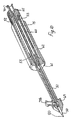
- FIG. 1 is a perspective, partially cut-away view of part of a rapid exchange stent delivery catheter according to the invention
- FIG. 2 is an exploded view of the delivery catheter of FIG. 1;
- FIG. 3 is a perspective, partially cut-away view of the delivery catheter
- FIG. 4 is a cross sectional view on the line IV—IV in FIG. 3;
- FIG. 5 is a cross sectional view on the line V—V in FIG. 3 .
- FIG. 6 is a side cross sectional view of part of the catheter of FIGS. 1 to 5 ;
- FIGS. 7 ( a ) to 7 ( d ) are diagrammatic views illustrating the delivery catheter of FIGS. 1 to 6 , in use;
- FIGS. 8 ( a ) to 8 ( d ) are views similar to FIGS. 7 ( a ) to 7 ( d ) with one stent deployment actuating mechanism;
- FIGS. 9 ( a ) to 9 ( d ) are views similar to FIGS. 7 ( a ) to 7 ( d ) with another stent deployment actuating mechanism;
- FIG. 10 is a perspective, partially cut-away cross sectional view of the stent deployment actuating mechanism of FIG. 8;
- FIG. 11 is a plan cross sectional view of the actuating mechanism of FIG. 10;
- FIG. 12 is a side elevational view of the actuating mechanism of FIG. 10;
- FIGS. 13 and 14 are side cross sectional views of the actuating mechanism of FIG. 10 in different positions of use;
- FIG. 15 is an exploded side view of a stent deployment system incorporating the actuating mechanism of FIG. 10;
- FIG. 16 is a plan view of a shuttle forming part of the actuating mechanism of FIG. 10;
- FIG. 17 is a side elevational view of the shuttle of FIG. 16;
- FIG. 18 is an end view of the shuttle FIGS. 16 and 17;
- FIG. 19 is a side elevational view of a shuttle nut forming part of the actuating mechanism of FIG. 10;
- FIG. 20 is a cross sectional view on the line XX—XX in FIG. 19;
- FIG. 21 is a plan view of a guide forming part of the actuating mechanism of FIG. 10;
- FIG. 22 is a diagrammatic exploded perspective view of one part of another actuating mechanism.
- FIG. 23 is a diagrammatic exploded perspective view of another part of the actuating mechanism of FIG. 22 .
- a rapid exchange stent delivery catheter 1 having a catheter shaft 2 defining a bore and a guidewire lumen 4 defined by a passageway having an entrance 5 and an exit 6 .
- a guidewire 7 extends through the lumen 4 .
- a stepped recess 10 is provided for receiving a stent 11 .
- the stent 11 is of a shape memory metallic alloy such as nitinol and is constrained in a pre-use constrained position by a sheath 20 .
- the sheath 20 prevents the stent 11 from-expanding until a desired location has been reached.
- the sheath 20 is then moved linearly by means of a stent deployment means to remove the constraint on the stent 11 and thereby allow it to be deployed by expanding into contact with a vessel wall 15 as illustrated in FIGS. 7 to 9 .
- the sheath 20 is movable to deploy the stent 11 without obstructing the guidewire lumen entrance 5 .
- An opening, in this case in the form of an elongate slot 25 is provided in the sheath 20 to align with the guidewire lumen entrance 5 so that the guidewire 7 is not obstructed during movement of the sheath 20 to deploy the stent 11 .
- the slot 25 has a length which is greater than or equal to the length of the stent 11 to be deployed and a width which is at least the same size as, and preferably larger than, the guidewire 7 so that, on linear movement of the sheath 20 , the guidewire entrance 5 is not interfered with.
- Actuating means for moving the sheath 20 to deploy the stent 11 is preferably a linear actuating means.
- the mechanism is used to move a rod or pull wire 50 which is attached directly or indirectly to the sheath 20 by any suitable jointing means.
- the sheath 20 may have its diameter reduced by way of a constraining shrink tube which may be shrunk onto either the rod 50 or alternatively onto an adhesive layer on the rod 50 .
- a ring bonded to sheath 20 may be attached to the rod 50 by welding, brazing or adhesive.
- the rod 50 is fixed to and extends from a shuttle shaft 51 which is movable on rotation of an operator handle defined by a knurled portion 52 of a shuttle nut 53 . On rotation of the nut 53 the rod 50 is drawn inwardly from the extended position illustrated in FIGS. 10 to 13 to the retracted position illustrated in FIG. 14 .
- the shuttle shaft 51 is bonded to a shuttle 55 having a screw threaded portion 56 which screw threadingly engages a corresponding screw threaded portion 57 on the inner surface of the shuttle nut 53 .
- the screw threaded portion 56 of the shuttle 55 is provided on two radially extending wings 58 which are located, on assembly, in corresponding opposed elongated slots 59 defined by elongate arms of a guide 60 .
- the guide 60 has an end-cap forming end 61 which engages, on assembly in an outer body tube 62 of the mechanism. An opposite end of the assembly is closed by an end cap 65 which is a force fit in the barrel of the shuttle nut 53 .
- Female luer connectors 70 a , 70 b are provided in the end cap 65 and in an elongated head portion 69 of the shuttle shaft 51 respectively.
- the rod 50 has an inner core 80 which extends back through the actuating mechanism.
- the rod 50 which moves the sheath 20 is independently movable of the inner core 80 .
- the rod 50 terminates in the head portion 69 of the shuttle shaft 51 .
- the inner core 80 however continues back through the shuttle shaft 51 , the inside of the shuttle 55 , an inner tube 75 and is mounted to the rear end cap 65 .
- the end cap 65 has a bore 81 in fluid ccmmunication with the luer connector 70 a for flushing the inner core 80 .
- the inner core 80 itself has two lumens and the second luer connector 70 b provides a fluid connection for flushing.
- An O-ring 82 seals the annulus between the inner core 80 and the inner tube 75 .
- the outer body of the rod 50 is isolated from the inner core 80 .
- a multi-start thread is desirable to allow linear actuation in a ratio suitable for the actuation 4 handle in the clinical setting.
- the ratio of the number of turns to linear travel should be such that a stent of say 10 mm in length should not require excessive rotation.
- Using a single start thread would require a helix angle that could cause the rotator to bind up.
- the device is therefore preferably actuated by way of a two start thread as illustrated particularly in FIGS. 17 and 20. Even more desirably the device is actuated by way of a four start thread as illustrated in FIGS. 22 and 23.
- a thread with a number of starts is preferred as additional points of contact are provided for load sharing.
- the linear actuating. means comprises a threaded rod 40 rotatably engaged by a thumbwheel 41 .
- the arrangement is such that on rotation of the thumbwheel 41 , the rod 40 is moved linearly.
- An anti rotation pin 47 may be provided to prevent the rotation of the threaded rod during pull back of the sheath to release the stent 11 .
- the rod 40 may be joined to a pull wire 45 , for example, by brazing.
- the pull wire 45 may in turn be joined to the sheath 20 by any suitable jointing means.
- the sheath 20 may have it's diameter reduced by way of a constraining shrink tube. This ma y be shrunk onto either the pull wire 45 or alternately onto an adhesive layer on the wire 45 .
- a ring bonded to the sheath 20 may be attached to the pull wire 45 by welding, brazing or adhesive jointing.
- the linear actuation mechanism may be attached to the sheath 20 at any point along its length.
- the attachment may be distal to the guidewire entrance lumen, at or near the lumen or at or close to the proximal end.
- constriction means may be in the form of a curved wrap-around body, for example in the form of a helix or part thereof.
- the stent may be of any suitable size or shape and may be of any desired material of construction.
Abstract
A rapid exchange stent delivery catheter for delivery and deployment of a stent has a catheter shaft having a guidewire lumen defined by a passageway with an entrance and an exit. The stent is of a shape memory metallic alloy and is constrained by a sheath. The sheath has an elongate slot aligned with the guidewire lumen entrance so that a guidewire is not obstructed during movement of the sheath to deploy the stent. The sheath is pulled back linearly by a thumbscrew mechanism to deploy the stent.
Description
This is a continuation of PCT Application No. PCT/IE99/00018, filed Mar. 31, 1999.
The invention relates to a delivery system for delivery and deployment of a stent, to a desired vascular location.
Vascular intervention is today undertaken to treat a large number of diseases that had heretofore been treated by surgery. Stents are used widely in a number of applications to provide structural support to vessels that are being treated. Typically, a vascular intervention procedure is required to restore the flow of blood through an artery that has been constricted by a build up of atherosclerotic material. Medical practice has shown that implanting stents at the site of disease is effective. Various types of stents have been devised and the therapy is well known and widely practised.
Stent designs are broadly divided into two categories, balloon expandable stents and self-expanding stents. The invention relates particularly to the delivery and positioning of self-expanding stents. The term self-expanding refers to the inherent material properties of the stent which cause the expansion of the stent once an external constraint has been removed. The effect is most commonly achieved by using a shape memory metallic alloy such as nitinol.
Generally, stents are delivered to the desired location by means of a catheter, specifically referred to as a delivery catheter. Delivery catheters are threaded through a guiding catheter to the site of the disease and once the correct position has been established by means of fluoroscopic or other imaging method, the stent is deployed.
There is however a problem with conventional stent delivery systems in that it is difficult and time consuming to deploy stents. A full length over the wire catheter is used in combination with an exchange length guidewire over which the delivery catheter is manipulated. Such systems are cumbersome to handle and a second operator is generally required to assist the lead clinician in controlling the procedure. When the guidewire is positioned at the commencement of the procedure, it is desirable that it's position is stable during the remainder of the procedure as it provides access to the treatment site for the therapeutic or diagnostic devices used in treatment. If it is desirous to insert or exchange a catheter, it is necessary to thread the catheter over the guidewire while retaining control of the guidewire. This is achievable only if the length of available guidewire outside the body is greater than the length of the catheter being loaded. Intravascular catheters typically measure 1.3 metres or more. It is impossible for one clinician to maintain position and control of a guidewire and simultaneously thread on a catheter more than a metre away.
There is therefore a need for a delivery catheter system which will overcome at least some of these difficulties.
According to the invention there is provided a stent delivery catheter for delivery and deployment of a stent comprising:
an elongate catheter body;
a self-expanding stent overlying said catheter body at a distal end thereof;
a sheath overlying said stent to constrict the stent during delivery;
the catheter body having a guidewire lumen with a guidewire exit at a distal end of the catheter body and a guidewire entrance proximal of the stent;
a guidewire extending through the lumen between the guidewire entrance and the guidewire exit; and
stent deployment means comprising means for moving the sheath relative to the catheter body to release the stent;
the sheath having guidewire accommodating means for accommodating the guidewire so that the guidewire entrance is not obstructed during movement of the sheath relative to the catheter body.
Most preferably the guidewire accommodating means is an opening in the sheath which is arranged to align with the guidewire entrance to prevent obstruction of the entrance on deployment of the stent.
Preferably the guidewire accommodating means is configured to correspond with the operation of the stent deployment means.
In a preferred arrangement the sheath opening has a length which is greater than or equal to the length of the stent to be deployed.
Ideally the sheath opening comprises an elongate slot.
Preferably the stent deployment means is a linear actuating means. In a preferred arrangement the actuating means includes converter means for converting rotational movement of an actuator into linear motion to move the sheath linearly.
Preferably the converter means comprises a shuttle which is linearly movable within a shuttle guide, on rotation of the actuator.
Ideally the shuttle screw threadingly engages the actuator. Preferably the thread has at least two starts. Ideally, the thread is a four start thread.
In one embodiment of the invention the actuator is a shuttle nut. Preferably the shuttle nut includes an operator handle. The operator handle may be a knurled portion of the shuttle nut.
In a particularly preferred arrangement the shuttle has at least two wings and the guide includes corresponding slots to substantially prevent rotation of the wings on rotation of the actuator. The oppositely directed wings have the effect of stabilising the shuttle in the guide slots.
A shuttle shaft preferably is connected to and extends forwardly of the shuttle. The shuttle shaft thereby provides an extension of the shuttle. Preferably the sheath is attached to the shuttle shaft.
The actuating means may comprise a threaded shaft and an associated thumbwheel which is rotated to move the shaft linearly. An anti-rotation means to control rotation of the threaded shaft is preferably provided. The thread on the shaft may be discontinuous. Ideally the thread is a multistart thread, preferably a four start thread.
In another arrangement the restraining sheath is slit helically at one or more circumferential location such that a combined linear and rotational motion of the sheath will maintain the opening for the guidewire to pass freely.
Preferably the stent deployment means is attached to the sheath. Typically, the actuating means includes a pull wire attached directly or indirectly to the sheath.
The invention also provides a constriction sheath for use with a delivery catheter of the invention. The constriction sheath has an opening which may be arranged to align with the guidewire lumen entrance to prevent obstruction of the entrance on movement of the constriction sheath.
In a particularly preferred arrangement the opening is an elongate slot having a length which is greater than or equal to the length of a stent to be deployed.
The invention further provides a catheter for deploying a stent, the catheter having a pathway extending longitudinally and in parallel with a coaxial guidewire to permit free movement of the guidewire and providing a path for a stent release means.
Thus, the invention provides a means for rapidly deploying a self-expanding stent by way of a pull or push motion of the sheath without interference with any guidewire path.
The invention also provides a restraining sheath that is slit longitudinally at one or more circumferential location such that linear motion of the sheath will maintain the opening for the guidewire to pass freely.
The invention further provides a restraining sheath that is slit helically at one or more circurmfrential location such that a combined linear and rotational motion of the sheath will maintain the opening for the guidewire to pass freely.
The invention further provides a rapid exchange stent delivery catheter having a pathway extending longitudinally and in parallel with a coaxial guidewire to permit movement of the guidewire and providing a path for a pull wire or suture used to release a stent restraining sheath.
The invention will be more clearly understood from the following description thereof given by way of example only in which:
FIG. 1 is a perspective, partially cut-away view of part of a rapid exchange stent delivery catheter according to the invention;
FIG. 2 is an exploded view of the delivery catheter of FIG. 1;
FIG. 3 is a perspective, partially cut-away view of the delivery catheter;
FIG. 4 is a cross sectional view on the line IV—IV in FIG. 3;
FIG. 5 is a cross sectional view on the line V—V in FIG. 3.
FIG. 6 is a side cross sectional view of part of the catheter of FIGS. 1 to 5;
FIGS. 7(a) to 7(d) are diagrammatic views illustrating the delivery catheter of FIGS. 1 to 6, in use;
FIGS. 8(a) to 8(d) are views similar to FIGS. 7(a) to 7(d) with one stent deployment actuating mechanism;
FIGS. 9(a) to 9(d) are views similar to FIGS. 7(a) to 7(d) with another stent deployment actuating mechanism;
FIG. 10 is a perspective, partially cut-away cross sectional view of the stent deployment actuating mechanism of FIG. 8;
FIG. 11 is a plan cross sectional view of the actuating mechanism of FIG. 10;
FIG. 12 is a side elevational view of the actuating mechanism of FIG. 10;
FIGS. 13 and 14 are side cross sectional views of the actuating mechanism of FIG. 10 in different positions of use;
FIG. 15 is an exploded side view of a stent deployment system incorporating the actuating mechanism of FIG. 10;
FIG. 16 is a plan view of a shuttle forming part of the actuating mechanism of FIG. 10;
FIG. 17 is a side elevational view of the shuttle of FIG. 16;
FIG. 18 is an end view of the shuttle FIGS. 16 and 17;
FIG. 19 is a side elevational view of a shuttle nut forming part of the actuating mechanism of FIG. 10;
FIG. 20 is a cross sectional view on the line XX—XX in FIG. 19;
FIG. 21 is a plan view of a guide forming part of the actuating mechanism of FIG. 10;
FIG. 22 is a diagrammatic exploded perspective view of one part of another actuating mechanism; and
FIG. 23 is a diagrammatic exploded perspective view of another part of the actuating mechanism of FIG. 22.
Referring to the drawings there is illustrated a rapid exchange stent delivery catheter 1 having a catheter shaft 2 defining a bore and a guidewire lumen 4 defined by a passageway having an entrance 5 and an exit 6. A guidewire 7 extends through the lumen 4. Around the lumen 4 a stepped recess 10 is provided for receiving a stent 11. The stent 11 is of a shape memory metallic alloy such as nitinol and is constrained in a pre-use constrained position by a sheath 20. The sheath 20 prevents the stent 11 from-expanding until a desired location has been reached. By loading the distal end of the lumen over a guidewire 7 it is possible to advance the catheter to any desired position. The sheath 20 is then moved linearly by means of a stent deployment means to remove the constraint on the stent 11 and thereby allow it to be deployed by expanding into contact with a vessel wall 15 as illustrated in FIGS. 7 to 9.
The sheath 20 is movable to deploy the stent 11 without obstructing the guidewire lumen entrance 5. An opening, in this case in the form of an elongate slot 25 is provided in the sheath 20 to align with the guidewire lumen entrance 5 so that the guidewire 7 is not obstructed during movement of the sheath 20 to deploy the stent 11. The slot 25 has a length which is greater than or equal to the length of the stent 11 to be deployed and a width which is at least the same size as, and preferably larger than, the guidewire 7 so that, on linear movement of the sheath 20, the guidewire entrance 5 is not interfered with.
Actuating means for moving the sheath 20 to deploy the stent 11 is preferably a linear actuating means. Referring to FIGS. 10 to 14 there is illustrated one such stent deployment/actuating mechanism. The mechanism is used to move a rod or pull wire 50 which is attached directly or indirectly to the sheath 20 by any suitable jointing means. For example, the sheath 20 may have its diameter reduced by way of a constraining shrink tube which may be shrunk onto either the rod 50 or alternatively onto an adhesive layer on the rod 50. Alternatively, a ring bonded to sheath 20 may be attached to the rod 50 by welding, brazing or adhesive.
The rod 50 is fixed to and extends from a shuttle shaft 51 which is movable on rotation of an operator handle defined by a knurled portion 52 of a shuttle nut 53. On rotation of the nut 53 the rod 50 is drawn inwardly from the extended position illustrated in FIGS. 10 to 13 to the retracted position illustrated in FIG. 14.
The shuttle shaft 51 is bonded to a shuttle 55 having a screw threaded portion 56 which screw threadingly engages a corresponding screw threaded portion 57 on the inner surface of the shuttle nut 53. The screw threaded portion 56 of the shuttle 55 is provided on two radially extending wings 58 which are located, on assembly, in corresponding opposed elongated slots 59 defined by elongate arms of a guide 60. The guide 60 has an end-cap forming end 61 which engages, on assembly in an outer body tube 62 of the mechanism. An opposite end of the assembly is closed by an end cap 65 which is a force fit in the barrel of the shuttle nut 53. Female luer connectors 70 a, 70 b are provided in the end cap 65 and in an elongated head portion 69 of the shuttle shaft 51 respectively.
The rod 50 has an inner core 80 which extends back through the actuating mechanism. The rod 50 which moves the sheath 20 is independently movable of the inner core 80. The rod 50 terminates in the head portion 69 of the shuttle shaft 51. The inner core 80 however continues back through the shuttle shaft 51, the inside of the shuttle 55, an inner tube 75 and is mounted to the rear end cap 65. The end cap 65 has a bore 81 in fluid ccmmunication with the luer connector 70 a for flushing the inner core 80. The inner core 80 itself has two lumens and the second luer connector 70 b provides a fluid connection for flushing. An O-ring 82 seals the annulus between the inner core 80 and the inner tube 75. Thus, the outer body of the rod 50 is isolated from the inner core 80.
In use, the side wings 58 of the shuttle 55 are trapped in the guide slots 59 of the guide 60 to prevent rotation of the shuttle 55 as the threads 56, 59 engage on rotation of the shuttle nut 53. Thus, the rotational motion of the shuttle nut 53 is converted in to a linear movement of the shuttle 55 which in turn moves the shuttle shaft 51 and the rod 50, to which it is attached, linearly. This is most clearly illustrated in relation to the embodiment of FIGS. 22 and 23
The threading engagement between the threaded wings 58 of the shuttle 55 and the thread 57 inside the shuttle nut 53 provides ease of operation. A multi-start thread is desirable to allow linear actuation in a ratio suitable for the actuation 4 handle in the clinical setting. The ratio of the number of turns to linear travel should be such that a stent of say 10 mm in length should not require excessive rotation. Using a single start thread would require a helix angle that could cause the rotator to bind up. The device is therefore preferably actuated by way of a two start thread as illustrated particularly in FIGS. 17 and 20. Even more desirably the device is actuated by way of a four start thread as illustrated in FIGS. 22 and 23. A thread with a number of starts is preferred as additional points of contact are provided for load sharing.
Referring particularly to FIGS. 9(a) to 9(d) in this example the linear actuating. means comprises a threaded rod 40 rotatably engaged by a thumbwheel 41. The arrangement is such that on rotation of the thumbwheel 41, the rod 40 is moved linearly. An anti rotation pin 47 may be provided to prevent the rotation of the threaded rod during pull back of the sheath to release the stent 11. The rod 40 may be joined to a pull wire 45, for example, by brazing. The pull wire 45 may in turn be joined to the sheath 20 by any suitable jointing means. For example, the sheath 20 may have it's diameter reduced by way of a constraining shrink tube. This ma y be shrunk onto either the pull wire 45 or alternately onto an adhesive layer on the wire 45. Alternatively, a ring bonded to the sheath 20 may be attached to the pull wire 45 by welding, brazing or adhesive jointing.
It will be appreciated that the linear actuation mechanism may be attached to the sheath 20 at any point along its length. For example, the attachment may be distal to the guidewire entrance lumen, at or near the lumen or at or close to the proximal end.
It will also be appreciated that while a slot is shown as a preferred embodiment, any configuration of sheath that is not continuous in it's circumference could be used to achieve the end objective of having a method of attachment to the stent covering sheath. For example, the constriction means may be in the form of a curved wrap-around body, for example in the form of a helix or part thereof.
It will further be appreciated that the stent may be of any suitable size or shape and may be of any desired material of construction.
The invention is not limited to the embodiments hereinbefore described which may be varied in construction and detail.
Claims (11)
1. A rapid exchange stent delivery catheter for delivery and deployment of a stent comprising:
an elongate catheter body;
a self-expanding stent overlying said catheter body at a distal end thereof;
a sheath overlying said stent to constrict the stent during delivery;
the catheter body having a guidewire lumen with a guidewire exit at a distal end of the catheter body and a guidewire entrance proximal of the stent;
a guidewire extending through the lumen between the guidewire entrance and the guidewire exit; and
a stent deployment assembly that moves the sheath relative to the catheter body to release the stent, the stent deployment assembly comprises a threaded shaft having a discontinuous thread, and a thumbwheel which is rotated to move the shaft linearly;
the sheath comprises a sheath opening arranged to align with the guidewire entrance and accomodate the guidewire so that the guidewire entrance is not obstructed during movement of the sheath relative to the catheter body on deployment of the stent.
2. A delivery catheter as claimed in claim 1 wherein the sheath opening is configured to correspond with the operation of the stent deployment assembly.
3. A delivery catheter as claimed in claim 1 wherein the sheath opening has a length which is greater than or equal to the length of the stent to be deployed.
4. A delivery catheter as claimed in claim 3 wherein the sheath opening comprises an elongate slot.
5. A delivery catheter as claimed in claim 1 further comprising an anti-rotation device to control rotation of the threaded shaft.
6. A delivery catheter as claimed in claim 1 wherein the thread is a multistart thread.
7. A delivery catheter as claimed in claim 6 , wherein the thread is a four start thread.
8. A delivery catheter as claimed in claim 1 wherein the sheath opening is a helical slot such that a combined linear and rotational motion of the sheath maintains the opening for the guidewire.
9. A delivery catheter as claimed in claim 1 wherein the stent deployment assembly is attached to the sheath.
10. A delivery catheter as claimed in claim 9 wherein the stent deployment assembly comprises a pull wire attached directly or indirectly to the sheath.
11. A delivery catheter as claimed in claim 1 wherein the sheath opening is an elongate slot.
Applications Claiming Priority (3)
| Application Number | Priority Date | Filing Date | Title |
|---|---|---|---|
| IE980235 | 1998-03-31 | ||
| IE980235 | 1998-03-31 | ||
| PCT/IE1999/000018 WO1999049808A1 (en) | 1998-03-31 | 1999-03-31 | A delivery catheter |
Related Parent Applications (1)
| Application Number | Title | Priority Date | Filing Date |
|---|---|---|---|
| PCT/IE1999/000018 Continuation WO1999049808A1 (en) | 1998-03-31 | 1999-03-31 | A delivery catheter |
Publications (1)
| Publication Number | Publication Date |
|---|---|
| US6669716B1 true US6669716B1 (en) | 2003-12-30 |
Family
ID=11041750
Family Applications (1)
| Application Number | Title | Priority Date | Filing Date |
|---|---|---|---|
| US09/672,014 Expired - Lifetime US6669716B1 (en) | 1998-03-31 | 2000-09-29 | Delivery catheter |
Country Status (4)
| Country | Link |
|---|---|
| US (1) | US6669716B1 (en) |
| EP (1) | EP1067882A1 (en) |
| AU (1) | AU3342399A (en) |
| WO (1) | WO1999049808A1 (en) |
Cited By (115)
| Publication number | Priority date | Publication date | Assignee | Title |
|---|---|---|---|---|
| US20030188052A1 (en) * | 2002-03-07 | 2003-10-02 | Hamilton Tony G. | Scalable logic |
| US20040093056A1 (en) * | 2002-10-26 | 2004-05-13 | Johnson Lianw M. | Medical appliance delivery apparatus and method of use |
| US20050010138A1 (en) * | 2003-07-11 | 2005-01-13 | Mangiardi Eric K. | Lumen-measuring devices and method |
| US20050033403A1 (en) * | 2003-08-01 | 2005-02-10 | Vance Products, Inc. D/B/A Cook Urological Incorporated | Implant delivery device |
| US20050060016A1 (en) * | 2003-09-12 | 2005-03-17 | Wu Patrick P. | Delivery system for medical devices |
| US20050065591A1 (en) * | 2004-10-08 | 2005-03-24 | Scimed Life Systems, Inc. | Endoprosthesis delivery system |
| US20050154439A1 (en) * | 2004-01-08 | 2005-07-14 | Gunderson Richard C. | Medical device delivery systems |
| US20060217759A1 (en) * | 2003-08-07 | 2006-09-28 | Jason Reynolds | Therapeutic medical appliance delivery and method of use |
| US20060229657A1 (en) * | 2005-03-30 | 2006-10-12 | Wasicek Lawrence D | Single operator exchange embolic protection filter |
| WO2007070788A2 (en) * | 2005-12-13 | 2007-06-21 | Cordis Development Corporation | Rotational detachment mechanism |
| US20070156224A1 (en) * | 2006-01-04 | 2007-07-05 | Iulian Cioanta | Handle system for deploying a prosthetic implant |
| US20070233222A1 (en) * | 2006-02-21 | 2007-10-04 | Med Institute, Inc. | Split sheath deployment system |
| US20070244439A1 (en) * | 2006-04-03 | 2007-10-18 | Ams Research Corporation | Linear Motion Delivery System for Female Sterilization Device |
| US20070255390A1 (en) * | 2006-04-27 | 2007-11-01 | William A. Cook Australia Pty. Ltd. | Rotary handle for controlled sequential deployment device |
| US20070270937A1 (en) * | 2006-05-19 | 2007-11-22 | Boston Scientific Scimed, Inc. | Apparatus and method for loading and delivering a stent |
| US20070270931A1 (en) * | 2006-05-19 | 2007-11-22 | Boston Scientific Scimed, Inc. | Apparatus and method for loading and delivering a stent using a suture retaining mechanism |
| US20070293934A1 (en) * | 2006-06-19 | 2007-12-20 | Med Institute, Inc. | Prosthesis Delivery and Deployment Device |
| EP1887977A2 (en) * | 2005-06-08 | 2008-02-20 | Xtent, Inc. | Devices and methods for operating and controlling interventional apparatus |
| US20080091229A1 (en) * | 2002-01-17 | 2008-04-17 | Boston Scientific Scimed, Inc. | Delivery and retrieval manifold for a distal protection filter |
| US20080183184A1 (en) * | 2007-01-29 | 2008-07-31 | U.S. Endoscopy Group, Inc. | Endoscopic device |
| US20080294230A1 (en) * | 2007-05-24 | 2008-11-27 | Cook Incorporated | Apparatus and methods for deploying self-expanding stents |
| US20080294231A1 (en) * | 2007-05-16 | 2008-11-27 | Boston Scientific Scimed, Inc. | Stent Delivery Catheter |
| US20090024137A1 (en) * | 2007-07-16 | 2009-01-22 | Cook Incorporated | Prosthesis Delivery and Deployment Device |
| US20090088790A1 (en) * | 2007-09-28 | 2009-04-02 | Parodi Juan C | Retrieval catheter |
| US20090099638A1 (en) * | 2007-10-11 | 2009-04-16 | Med Institute, Inc. | Motorized deployment system |
| US20090157048A1 (en) * | 2007-12-18 | 2009-06-18 | Boston Scientific Scimed, Inc. | Spiral cut hypotube |
| US20090177185A1 (en) * | 2008-01-03 | 2009-07-09 | Boston Scientific Scimed, Inc. | Cut tubular members for a medical device and methods for making and using the same |
| US20090210046A1 (en) * | 2008-02-20 | 2009-08-20 | Abbott Laboratories | Handle assembly for a delivery system |
| US20100036472A1 (en) * | 2008-08-08 | 2010-02-11 | Abbott Cardiovascular Systems Inc. | Delivery system with variable delivery rate for deploying a medical device |
| US20100204774A1 (en) * | 2006-03-06 | 2010-08-12 | Boston Scientific Scimed, Inc. | Stent delivery catheter |
| US7785360B2 (en) | 2001-09-28 | 2010-08-31 | Merit Medical Systems, Inc. | Instrument for implanting vascular prostheses |
| US7794473B2 (en) * | 2004-11-12 | 2010-09-14 | C.R. Bard, Inc. | Filter delivery system |
| US20110288558A1 (en) * | 2009-10-07 | 2011-11-24 | Cook Incorporated | Deployment handle for an introducer |
| US8216295B2 (en) | 2008-07-01 | 2012-07-10 | Endologix, Inc. | Catheter system and methods of using same |
| US20120226341A1 (en) * | 2011-03-01 | 2012-09-06 | Endologix, Inc. | Catheter system and methods of using same |
| US8292827B2 (en) | 2005-12-12 | 2012-10-23 | Boston Scientific Scimed, Inc. | Micromachined medical devices |
| US8298277B2 (en) | 2003-03-31 | 2012-10-30 | Merit Medical Systems, Inc. | Medical appliance optical delivery and deployment apparatus and method |
| US20120289972A1 (en) * | 2011-05-10 | 2012-11-15 | Biotronik Ag | Handheld device for stent implantation |
| US8353946B2 (en) | 2003-05-01 | 2013-01-15 | Merit Medical Systems, Inc. | Bifurcated medical appliance delivery apparatus and method |
| US8523933B2 (en) | 2011-05-11 | 2013-09-03 | Cook Medical Technologies Llc | Rotation operated delivery device |
| US20130231736A1 (en) * | 2010-09-10 | 2013-09-05 | Symetis Sa | Catheter Delivery System For Stent Valve |
| US8709060B2 (en) | 2005-12-23 | 2014-04-29 | Cook Medical Technologies Llc | Prosthesis deployment system |
| US8784468B2 (en) | 2010-11-17 | 2014-07-22 | Boston Scientific Scimed, Inc. | Stent delivery systems and locking members for use with stent delivery systems |
| US9084692B2 (en) | 2010-11-17 | 2015-07-21 | Boston Scientific Scimed, Inc. | Stent delivery system |
| US9101507B2 (en) | 2011-05-18 | 2015-08-11 | Ralph F. Caselnova | Apparatus and method for proximal-to-distal endoluminal stent deployment |
| CN105050549A (en) * | 2012-08-10 | 2015-11-11 | 阿尔图拉医疗公司 | Stent delivery systems and associated methods |
| US9204888B2 (en) | 2007-06-08 | 2015-12-08 | United States Endoscopy Group, Inc. | Retrieval device |
| US9220619B2 (en) | 2010-11-17 | 2015-12-29 | Boston Scientific Scimed, Inc. | Stent delivery system |
| US9286673B2 (en) | 2012-10-05 | 2016-03-15 | Volcano Corporation | Systems for correcting distortions in a medical image and methods of use thereof |
| US9292918B2 (en) | 2012-10-05 | 2016-03-22 | Volcano Corporation | Methods and systems for transforming luminal images |
| US9301687B2 (en) | 2013-03-13 | 2016-04-05 | Volcano Corporation | System and method for OCT depth calibration |
| US9307926B2 (en) | 2012-10-05 | 2016-04-12 | Volcano Corporation | Automatic stent detection |
| US9324141B2 (en) | 2012-10-05 | 2016-04-26 | Volcano Corporation | Removal of A-scan streaking artifact |
| US9339632B2 (en) | 2006-09-27 | 2016-05-17 | Boston Scientific Scimed, Inc. | Catheter shaft designs |
| US9360630B2 (en) | 2011-08-31 | 2016-06-07 | Volcano Corporation | Optical-electrical rotary joint and methods of use |
| US9367965B2 (en) | 2012-10-05 | 2016-06-14 | Volcano Corporation | Systems and methods for generating images of tissue |
| US9383263B2 (en) | 2012-12-21 | 2016-07-05 | Volcano Corporation | Systems and methods for narrowing a wavelength emission of light |
| US20160206456A1 (en) * | 2015-01-16 | 2016-07-21 | Boston Scientific Scimed, Inc. | Medical device delivery system with force reduction member |
| US9478940B2 (en) | 2012-10-05 | 2016-10-25 | Volcano Corporation | Systems and methods for amplifying light |
| US9486143B2 (en) | 2012-12-21 | 2016-11-08 | Volcano Corporation | Intravascular forward imaging device |
| US9486188B2 (en) | 2001-05-18 | 2016-11-08 | United States Endoscopy Group, Inc. | Retrieval device |
| US9572591B2 (en) | 2013-09-03 | 2017-02-21 | United States Endoscopy Group, Inc. | Endoscopic snare device |
| US9572652B2 (en) | 2009-12-01 | 2017-02-21 | Altura Medical, Inc. | Modular endograft devices and associated systems and methods |
| US9596993B2 (en) | 2007-07-12 | 2017-03-21 | Volcano Corporation | Automatic calibration systems and methods of use |
| US9612105B2 (en) | 2012-12-21 | 2017-04-04 | Volcano Corporation | Polarization sensitive optical coherence tomography system |
| US9622706B2 (en) | 2007-07-12 | 2017-04-18 | Volcano Corporation | Catheter for in vivo imaging |
| US9709379B2 (en) | 2012-12-20 | 2017-07-18 | Volcano Corporation | Optical coherence tomography system that is reconfigurable between different imaging modes |
| US9717614B2 (en) | 2014-02-16 | 2017-08-01 | Cook Medical Technologies Llc | Deployment handle for a prosthesis delivery device |
| US9730613B2 (en) | 2012-12-20 | 2017-08-15 | Volcano Corporation | Locating intravascular images |
| US9737426B2 (en) | 2013-03-15 | 2017-08-22 | Altura Medical, Inc. | Endograft device delivery systems and associated methods |
| US9770172B2 (en) | 2013-03-07 | 2017-09-26 | Volcano Corporation | Multimodal segmentation in intravascular images |
| US9858668B2 (en) | 2012-10-05 | 2018-01-02 | Volcano Corporation | Guidewire artifact removal in images |
| US9867530B2 (en) | 2006-08-14 | 2018-01-16 | Volcano Corporation | Telescopic side port catheter device with imaging system and method for accessing side branch occlusions |
| US9872700B2 (en) | 2013-09-03 | 2018-01-23 | United States Endoscopy Group, Inc. | Endoscopic snare device |
| US10016292B2 (en) | 2014-04-18 | 2018-07-10 | Covidien Lp | Stent delivery system |
| US10058443B2 (en) | 2011-11-02 | 2018-08-28 | Boston Scientific Scimed, Inc. | Stent delivery systems and methods for use |
| US10058284B2 (en) | 2012-12-21 | 2018-08-28 | Volcano Corporation | Simultaneous imaging, monitoring, and therapy |
| US10070827B2 (en) | 2012-10-05 | 2018-09-11 | Volcano Corporation | Automatic image playback |
| US20180333042A1 (en) * | 2017-05-18 | 2018-11-22 | Loubert S. Suddaby | Self-anchoring endoscopy sheath |
| US10166003B2 (en) | 2012-12-21 | 2019-01-01 | Volcano Corporation | Ultrasound imaging with variable line density |
| US10191220B2 (en) | 2012-12-21 | 2019-01-29 | Volcano Corporation | Power-efficient optical circuit |
| US10219887B2 (en) | 2013-03-14 | 2019-03-05 | Volcano Corporation | Filters with echogenic characteristics |
| US10219780B2 (en) | 2007-07-12 | 2019-03-05 | Volcano Corporation | OCT-IVUS catheter for concurrent luminal imaging |
| US10226597B2 (en) | 2013-03-07 | 2019-03-12 | Volcano Corporation | Guidewire with centering mechanism |
| US10238367B2 (en) | 2012-12-13 | 2019-03-26 | Volcano Corporation | Devices, systems, and methods for targeted cannulation |
| US10292677B2 (en) | 2013-03-14 | 2019-05-21 | Volcano Corporation | Endoluminal filter having enhanced echogenic properties |
| US10332228B2 (en) | 2012-12-21 | 2019-06-25 | Volcano Corporation | System and method for graphical processing of medical data |
| US10413317B2 (en) | 2012-12-21 | 2019-09-17 | Volcano Corporation | System and method for catheter steering and operation |
| US10420530B2 (en) | 2012-12-21 | 2019-09-24 | Volcano Corporation | System and method for multipath processing of image signals |
| US10426590B2 (en) | 2013-03-14 | 2019-10-01 | Volcano Corporation | Filters with echogenic characteristics |
| US10441449B1 (en) | 2018-05-30 | 2019-10-15 | Vesper Medical, Inc. | Rotary handle stent delivery system and method |
| US10449073B1 (en) | 2018-09-18 | 2019-10-22 | Vesper Medical, Inc. | Rotary handle stent delivery system and method |
| US10568586B2 (en) | 2012-10-05 | 2020-02-25 | Volcano Corporation | Systems for indicating parameters in an imaging data set and methods of use |
| US10595820B2 (en) | 2012-12-20 | 2020-03-24 | Philips Image Guided Therapy Corporation | Smooth transition catheters |
| US10638939B2 (en) | 2013-03-12 | 2020-05-05 | Philips Image Guided Therapy Corporation | Systems and methods for diagnosing coronary microvascular disease |
| US10667838B2 (en) | 2017-01-09 | 2020-06-02 | United States Endoscopy Group, Inc. | Endoscopic snare device |
| US10724082B2 (en) | 2012-10-22 | 2020-07-28 | Bio-Rad Laboratories, Inc. | Methods for analyzing DNA |
| US10758207B2 (en) | 2013-03-13 | 2020-09-01 | Philips Image Guided Therapy Corporation | Systems and methods for producing an image from a rotational intravascular ultrasound device |
| US10939826B2 (en) | 2012-12-20 | 2021-03-09 | Philips Image Guided Therapy Corporation | Aspirating and removing biological material |
| US10942022B2 (en) | 2012-12-20 | 2021-03-09 | Philips Image Guided Therapy Corporation | Manual calibration of imaging system |
| US10993694B2 (en) | 2012-12-21 | 2021-05-04 | Philips Image Guided Therapy Corporation | Rotational ultrasound imaging catheter with extended catheter body telescope |
| US11013627B2 (en) | 2018-01-10 | 2021-05-25 | Boston Scientific Scimed, Inc. | Stent delivery system with displaceable deployment mechanism |
| US11026591B2 (en) | 2013-03-13 | 2021-06-08 | Philips Image Guided Therapy Corporation | Intravascular pressure sensor calibration |
| US11040140B2 (en) | 2010-12-31 | 2021-06-22 | Philips Image Guided Therapy Corporation | Deep vein thrombosis therapeutic methods |
| US20210186695A1 (en) * | 2019-12-20 | 2021-06-24 | Tendyne Holdings, Inc. | Distally Loaded Sheath and Loading Funnel |
| US11065137B2 (en) | 2016-02-26 | 2021-07-20 | Boston Scientific Scimed, Inc. | Stent delivery systems with a reduced profile |
| US11129737B2 (en) | 2015-06-30 | 2021-09-28 | Endologix Llc | Locking assembly for coupling guidewire to delivery system |
| US11141063B2 (en) | 2010-12-23 | 2021-10-12 | Philips Image Guided Therapy Corporation | Integrated system architectures and methods of use |
| US11154313B2 (en) | 2013-03-12 | 2021-10-26 | The Volcano Corporation | Vibrating guidewire torquer and methods of use |
| US11219541B2 (en) | 2020-05-21 | 2022-01-11 | Vesper Medical, Inc. | Wheel lock for thumbwheel actuated device |
| US11234816B2 (en) * | 2015-11-11 | 2022-02-01 | Edwards Lifesciences Corporation | Prosthetic valve delivery apparatus having clutch mechanism |
| US11272845B2 (en) | 2012-10-05 | 2022-03-15 | Philips Image Guided Therapy Corporation | System and method for instant and automatic border detection |
| US11351048B2 (en) | 2015-11-16 | 2022-06-07 | Boston Scientific Scimed, Inc. | Stent delivery systems with a reinforced deployment sheath |
| US11406498B2 (en) | 2012-12-20 | 2022-08-09 | Philips Image Guided Therapy Corporation | Implant delivery system and implants |
| US11602447B2 (en) | 2019-02-13 | 2023-03-14 | Boston Scientific Scimed Inc. | Stent delivery systems |
Families Citing this family (15)
| Publication number | Priority date | Publication date | Assignee | Title |
|---|---|---|---|---|
| US6527779B1 (en) | 2000-07-10 | 2003-03-04 | Endotex Interventional Systems, Inc. | Stent delivery device |
| US6786918B1 (en) | 2000-10-17 | 2004-09-07 | Medtronic Vascular, Inc. | Stent delivery system |
| US6592549B2 (en) | 2001-03-14 | 2003-07-15 | Scimed Life Systems, Inc. | Rapid exchange stent delivery system and associated components |
| US7780693B2 (en) | 2001-06-27 | 2010-08-24 | Salviac Limited | Catheter |
| US7789860B2 (en) | 2001-06-27 | 2010-09-07 | Salviac Limited | Catheter for delivery and/or retrieval of a medical device |
| US20040006380A1 (en) * | 2002-07-05 | 2004-01-08 | Buck Jerrick C. | Stent delivery system |
| US7887574B2 (en) | 2003-12-23 | 2011-02-15 | Scimed Life Systems, Inc. | Stent delivery catheter |
| US7468070B2 (en) | 2004-01-23 | 2008-12-23 | Boston Scientific Scimed, Inc. | Stent delivery catheter |
| CA2608160C (en) | 2005-05-09 | 2013-12-03 | Jurgen Dorn | Implant delivery device |
| CA2676787A1 (en) | 2007-02-05 | 2008-08-14 | Boston Scientific Limited | System with catheter system and an adaptor comprising a friction reducing sleeve, and methods of use |
| US7815601B2 (en) | 2007-02-05 | 2010-10-19 | Boston Scientific Scimed, Inc. | Rapid exchange enteral stent delivery system |
| US8758421B2 (en) | 2008-01-30 | 2014-06-24 | Boston Scientific Scimed, Inc. | Medical systems and related methods |
| IN2012DN02041A (en) | 2009-08-28 | 2015-08-21 | 3F Therapeutics Inc | |
| US8771335B2 (en) | 2009-09-21 | 2014-07-08 | Boston Scientific Scimed, Inc. | Rapid exchange stent delivery system |
| WO2013003450A1 (en) | 2011-06-27 | 2013-01-03 | Boston Scientific Scimed, Inc. | Stent delivery systems and methods for making and using stent delivery systems |
Citations (5)
| Publication number | Priority date | Publication date | Assignee | Title |
|---|---|---|---|---|
| EP0536610A1 (en) | 1991-10-11 | 1993-04-14 | Angiomed Ag | Stenosis dilatation device |
| US5534007A (en) * | 1995-05-18 | 1996-07-09 | Scimed Life Systems, Inc. | Stent deployment catheter with collapsible sheath |
| EP0819411A2 (en) | 1996-07-15 | 1998-01-21 | Advanced Cardiovascular Systems, Inc. | Self-expanding stent delivery system |
| US5827322A (en) * | 1994-11-16 | 1998-10-27 | Advanced Cardiovascular Systems, Inc. | Shape memory locking mechanism for intravascular stents |
| US5906619A (en) * | 1997-07-24 | 1999-05-25 | Medtronic, Inc. | Disposable delivery device for endoluminal prostheses |
-
1999
- 1999-03-31 AU AU33423/99A patent/AU3342399A/en not_active Abandoned
- 1999-03-31 EP EP99914727A patent/EP1067882A1/en not_active Withdrawn
- 1999-03-31 WO PCT/IE1999/000018 patent/WO1999049808A1/en not_active Application Discontinuation
-
2000
- 2000-09-29 US US09/672,014 patent/US6669716B1/en not_active Expired - Lifetime
Patent Citations (7)
| Publication number | Priority date | Publication date | Assignee | Title |
|---|---|---|---|---|
| EP0536610A1 (en) | 1991-10-11 | 1993-04-14 | Angiomed Ag | Stenosis dilatation device |
| US5433723A (en) | 1991-10-11 | 1995-07-18 | Angiomed Ag | Apparatus for widening a stenosis |
| US5827322A (en) * | 1994-11-16 | 1998-10-27 | Advanced Cardiovascular Systems, Inc. | Shape memory locking mechanism for intravascular stents |
| US5534007A (en) * | 1995-05-18 | 1996-07-09 | Scimed Life Systems, Inc. | Stent deployment catheter with collapsible sheath |
| EP0819411A2 (en) | 1996-07-15 | 1998-01-21 | Advanced Cardiovascular Systems, Inc. | Self-expanding stent delivery system |
| US6077295A (en) * | 1996-07-15 | 2000-06-20 | Advanced Cardiovascular Systems, Inc. | Self-expanding stent delivery system |
| US5906619A (en) * | 1997-07-24 | 1999-05-25 | Medtronic, Inc. | Disposable delivery device for endoluminal prostheses |
Cited By (196)
| Publication number | Priority date | Publication date | Assignee | Title |
|---|---|---|---|---|
| US9730716B2 (en) | 2001-05-18 | 2017-08-15 | United States Endoscopy Group, Inc. | Retrieval device |
| US9486188B2 (en) | 2001-05-18 | 2016-11-08 | United States Endoscopy Group, Inc. | Retrieval device |
| US10772648B2 (en) | 2001-05-18 | 2020-09-15 | United States Endoscopy Group, Inc. | Retrieval device |
| US7785360B2 (en) | 2001-09-28 | 2010-08-31 | Merit Medical Systems, Inc. | Instrument for implanting vascular prostheses |
| US7722638B2 (en) | 2002-01-17 | 2010-05-25 | Boston Scientific Scimed, Inc. | Delivery and retrieval manifold for a distal protection filter |
| US20080091229A1 (en) * | 2002-01-17 | 2008-04-17 | Boston Scientific Scimed, Inc. | Delivery and retrieval manifold for a distal protection filter |
| US20030188052A1 (en) * | 2002-03-07 | 2003-10-02 | Hamilton Tony G. | Scalable logic |
| US20040093056A1 (en) * | 2002-10-26 | 2004-05-13 | Johnson Lianw M. | Medical appliance delivery apparatus and method of use |
| US8267987B2 (en) | 2002-10-26 | 2012-09-18 | Merit Medical Systems, Inc. | Medical appliance delivery apparatus and method of use |
| US8298277B2 (en) | 2003-03-31 | 2012-10-30 | Merit Medical Systems, Inc. | Medical appliance optical delivery and deployment apparatus and method |
| US8353946B2 (en) | 2003-05-01 | 2013-01-15 | Merit Medical Systems, Inc. | Bifurcated medical appliance delivery apparatus and method |
| US8083692B2 (en) | 2003-07-11 | 2011-12-27 | Merit Medical Systems, Inc. | Lumen-measuring devices and method |
| US20110082392A1 (en) * | 2003-07-11 | 2011-04-07 | Merit Medical Systems, Inc. | Lumen-measuring devices and method |
| US20050010138A1 (en) * | 2003-07-11 | 2005-01-13 | Mangiardi Eric K. | Lumen-measuring devices and method |
| US20050033403A1 (en) * | 2003-08-01 | 2005-02-10 | Vance Products, Inc. D/B/A Cook Urological Incorporated | Implant delivery device |
| US20060217759A1 (en) * | 2003-08-07 | 2006-09-28 | Jason Reynolds | Therapeutic medical appliance delivery and method of use |
| US7757691B2 (en) | 2003-08-07 | 2010-07-20 | Merit Medical Systems, Inc. | Therapeutic medical appliance delivery and method of use |
| US8511310B2 (en) | 2003-08-07 | 2013-08-20 | Merit Medical Systems, Inc. | Therapeutic medical appliance delivery and method of use |
| US20050060016A1 (en) * | 2003-09-12 | 2005-03-17 | Wu Patrick P. | Delivery system for medical devices |
| US7758625B2 (en) * | 2003-09-12 | 2010-07-20 | Abbott Vascular Solutions Inc. | Delivery system for medical devices |
| US20050154439A1 (en) * | 2004-01-08 | 2005-07-14 | Gunderson Richard C. | Medical device delivery systems |
| US8152818B2 (en) | 2004-01-08 | 2012-04-10 | Boston Scientific Scimed, Inc. | Medical device delivery systems |
| US9039751B2 (en) | 2004-10-08 | 2015-05-26 | Boston Scientific Scimed, Inc. | Endoprosthesis delivery system |
| US7658757B2 (en) * | 2004-10-08 | 2010-02-09 | Boston Scientific Scimed, Inc. | Endoprosthesis delivery system |
| US20100121427A1 (en) * | 2004-10-08 | 2010-05-13 | Boston Scientific Scimed, Inc. | Endoprosthesis delivery system |
| US20050065591A1 (en) * | 2004-10-08 | 2005-03-24 | Scimed Life Systems, Inc. | Endoprosthesis delivery system |
| US10512531B2 (en) | 2004-11-12 | 2019-12-24 | C. R. Bard, Inc. | Filter delivery system |
| US8992562B2 (en) | 2004-11-12 | 2015-03-31 | C.R. Bard, Inc. | Filter delivery system |
| US20110034952A1 (en) * | 2004-11-12 | 2011-02-10 | C.R. Bard, Inc. | Filter delivery system |
| US7794473B2 (en) * | 2004-11-12 | 2010-09-14 | C.R. Bard, Inc. | Filter delivery system |
| US20060229657A1 (en) * | 2005-03-30 | 2006-10-12 | Wasicek Lawrence D | Single operator exchange embolic protection filter |
| EP1887977A2 (en) * | 2005-06-08 | 2008-02-20 | Xtent, Inc. | Devices and methods for operating and controlling interventional apparatus |
| EP1887977A4 (en) * | 2005-06-08 | 2010-01-27 | Xtent Inc | Devices and methods for operating and controlling interventional apparatus |
| US8292827B2 (en) | 2005-12-12 | 2012-10-23 | Boston Scientific Scimed, Inc. | Micromachined medical devices |
| WO2007070788A3 (en) * | 2005-12-13 | 2007-12-06 | Cordis Dev Corp | Rotational detachment mechanism |
| WO2007070788A2 (en) * | 2005-12-13 | 2007-06-21 | Cordis Development Corporation | Rotational detachment mechanism |
| US8709060B2 (en) | 2005-12-23 | 2014-04-29 | Cook Medical Technologies Llc | Prosthesis deployment system |
| EP1806114A3 (en) * | 2006-01-04 | 2008-05-14 | Cordis Corporation | Handle system for deploying a prosthetic implant |
| US20070156224A1 (en) * | 2006-01-04 | 2007-07-05 | Iulian Cioanta | Handle system for deploying a prosthetic implant |
| US9592140B2 (en) | 2006-02-21 | 2017-03-14 | Cook Medical Technologies Llc | Split sheath deployment system |
| US20070233222A1 (en) * | 2006-02-21 | 2007-10-04 | Med Institute, Inc. | Split sheath deployment system |
| US8518098B2 (en) | 2006-02-21 | 2013-08-27 | Cook Medical Technologies Llc | Split sheath deployment system |
| US20100204774A1 (en) * | 2006-03-06 | 2010-08-12 | Boston Scientific Scimed, Inc. | Stent delivery catheter |
| US20070244439A1 (en) * | 2006-04-03 | 2007-10-18 | Ams Research Corporation | Linear Motion Delivery System for Female Sterilization Device |
| US8562628B2 (en) * | 2006-04-03 | 2013-10-22 | Conceptus, Inc. | Linear motion delivery system for female sterilization device |
| US7780717B2 (en) * | 2006-04-27 | 2010-08-24 | Med Institute, Inc. | Rotary handle for controlled sequential deployment device |
| US20070255390A1 (en) * | 2006-04-27 | 2007-11-01 | William A. Cook Australia Pty. Ltd. | Rotary handle for controlled sequential deployment device |
| US8834550B2 (en) * | 2006-05-19 | 2014-09-16 | Boston Scientific Scimed, Inc. | Apparatus and method for loading and delivering a stent using a suture retaining mechanism |
| US9913742B2 (en) * | 2006-05-19 | 2018-03-13 | Boston Scientific Scimed, Inc. | Apparatus and method for loading and delivering a stent using a suture retaining mechanism |
| US8753384B2 (en) * | 2006-05-19 | 2014-06-17 | Boston Scientific Scimed, Inc. | Apparatus and method for loading and delivering a stent |
| US20070270937A1 (en) * | 2006-05-19 | 2007-11-22 | Boston Scientific Scimed, Inc. | Apparatus and method for loading and delivering a stent |
| US20140296959A1 (en) * | 2006-05-19 | 2014-10-02 | Boston Scientific Scimed, Inc. | Apparatus and method for loading and delivering a stent using a suture retaining mechanism |
| US20070270931A1 (en) * | 2006-05-19 | 2007-11-22 | Boston Scientific Scimed, Inc. | Apparatus and method for loading and delivering a stent using a suture retaining mechanism |
| US8118853B2 (en) | 2006-06-19 | 2012-02-21 | Cook Medical Technologies Llc | Prosthesis delivery and deployment device |
| US20070293934A1 (en) * | 2006-06-19 | 2007-12-20 | Med Institute, Inc. | Prosthesis Delivery and Deployment Device |
| US9867530B2 (en) | 2006-08-14 | 2018-01-16 | Volcano Corporation | Telescopic side port catheter device with imaging system and method for accessing side branch occlusions |
| US9339632B2 (en) | 2006-09-27 | 2016-05-17 | Boston Scientific Scimed, Inc. | Catheter shaft designs |
| US10315018B2 (en) | 2006-09-27 | 2019-06-11 | Boston Scientific Scimed Inc. | Catheter shaft designs |
| US8343168B2 (en) * | 2007-01-29 | 2013-01-01 | Us Endoscopy Group, Inc. | Endoscopic device |
| US20080183184A1 (en) * | 2007-01-29 | 2008-07-31 | U.S. Endoscopy Group, Inc. | Endoscopic device |
| EP2109392A4 (en) * | 2007-01-29 | 2016-02-24 | U S Endoscopy Group Inc | Endoscopic device |
| US7981148B2 (en) | 2007-05-16 | 2011-07-19 | Boston Scientific Scimed, Inc. | Stent delivery catheter |
| US20080294231A1 (en) * | 2007-05-16 | 2008-11-27 | Boston Scientific Scimed, Inc. | Stent Delivery Catheter |
| US20080294230A1 (en) * | 2007-05-24 | 2008-11-27 | Cook Incorporated | Apparatus and methods for deploying self-expanding stents |
| US9204888B2 (en) | 2007-06-08 | 2015-12-08 | United States Endoscopy Group, Inc. | Retrieval device |
| US11166735B2 (en) | 2007-06-08 | 2021-11-09 | United States Endoscopy Group, Inc. | Retrieval device |
| US9826997B2 (en) | 2007-06-08 | 2017-11-28 | U.S. Endoscopy Group, Inc. | Retrieval device |
| US10219780B2 (en) | 2007-07-12 | 2019-03-05 | Volcano Corporation | OCT-IVUS catheter for concurrent luminal imaging |
| US9596993B2 (en) | 2007-07-12 | 2017-03-21 | Volcano Corporation | Automatic calibration systems and methods of use |
| US11350906B2 (en) | 2007-07-12 | 2022-06-07 | Philips Image Guided Therapy Corporation | OCT-IVUS catheter for concurrent luminal imaging |
| US9622706B2 (en) | 2007-07-12 | 2017-04-18 | Volcano Corporation | Catheter for in vivo imaging |
| US20090024137A1 (en) * | 2007-07-16 | 2009-01-22 | Cook Incorporated | Prosthesis Delivery and Deployment Device |
| US9119742B2 (en) | 2007-07-16 | 2015-09-01 | Cook Medical Technologies Llc | Prosthesis delivery and deployment device |
| US20090088790A1 (en) * | 2007-09-28 | 2009-04-02 | Parodi Juan C | Retrieval catheter |
| US10449029B2 (en) | 2007-09-28 | 2019-10-22 | W. L. Gore & Associates, Inc. | Retrieval catheter |
| US9597172B2 (en) * | 2007-09-28 | 2017-03-21 | W. L. Gore & Associates, Inc. | Retrieval catheter |
| US11607302B2 (en) | 2007-09-28 | 2023-03-21 | W. L. Gore & Associates, Inc. | Retrieval catheter |
| US20090099638A1 (en) * | 2007-10-11 | 2009-04-16 | Med Institute, Inc. | Motorized deployment system |
| US20090157048A1 (en) * | 2007-12-18 | 2009-06-18 | Boston Scientific Scimed, Inc. | Spiral cut hypotube |
| US8460213B2 (en) | 2008-01-03 | 2013-06-11 | Boston Scientific Scimed, Inc. | Cut tubular members for a medical device and methods for making and using the same |
| US9227037B2 (en) | 2008-01-03 | 2016-01-05 | Boston Scientific Scimed, Inc. | Cut tubular members for a medical device and methods for making and using the same |
| US20090177185A1 (en) * | 2008-01-03 | 2009-07-09 | Boston Scientific Scimed, Inc. | Cut tubular members for a medical device and methods for making and using the same |
| US20090210046A1 (en) * | 2008-02-20 | 2009-08-20 | Abbott Laboratories | Handle assembly for a delivery system |
| US8216295B2 (en) | 2008-07-01 | 2012-07-10 | Endologix, Inc. | Catheter system and methods of using same |
| US10512758B2 (en) | 2008-07-01 | 2019-12-24 | Endologix, Inc. | Catheter system and methods of using same |
| US9700701B2 (en) | 2008-07-01 | 2017-07-11 | Endologix, Inc. | Catheter system and methods of using same |
| US7976574B2 (en) | 2008-08-08 | 2011-07-12 | Advanced Cardiovascular Systems, Inc. | Delivery system with variable delivery rate for deploying a medical device |
| US20100036472A1 (en) * | 2008-08-08 | 2010-02-11 | Abbott Cardiovascular Systems Inc. | Delivery system with variable delivery rate for deploying a medical device |
| US10278846B2 (en) * | 2009-10-07 | 2019-05-07 | Cook Medical Technologies Llc | Deployment handle for an introducer |
| US20150142095A1 (en) * | 2009-10-07 | 2015-05-21 | Cook Medical Technologies Llc | Deployment handle for an introducer |
| US11096811B2 (en) | 2009-10-07 | 2021-08-24 | Cook Medical Technologies Llc | Deployment handle for an introducer |
| US20110288558A1 (en) * | 2009-10-07 | 2011-11-24 | Cook Incorporated | Deployment handle for an introducer |
| US8968380B2 (en) * | 2009-10-07 | 2015-03-03 | Cook Medical Technologies Llc | Deployment handle for an introducer |
| US9572652B2 (en) | 2009-12-01 | 2017-02-21 | Altura Medical, Inc. | Modular endograft devices and associated systems and methods |
| US11779461B2 (en) | 2010-09-10 | 2023-10-10 | Symetis Sa | Catheter delivery system for stent valve |
| US20130231736A1 (en) * | 2010-09-10 | 2013-09-05 | Symetis Sa | Catheter Delivery System For Stent Valve |
| US9675485B2 (en) * | 2010-09-10 | 2017-06-13 | Symetis Sa | Catheter delivery system for stent valve |
| US9084692B2 (en) | 2010-11-17 | 2015-07-21 | Boston Scientific Scimed, Inc. | Stent delivery system |
| US9220619B2 (en) | 2010-11-17 | 2015-12-29 | Boston Scientific Scimed, Inc. | Stent delivery system |
| US9974679B2 (en) | 2010-11-17 | 2018-05-22 | Boston Scientific Scimed, Inc. | Stent delivery system |
| US8784468B2 (en) | 2010-11-17 | 2014-07-22 | Boston Scientific Scimed, Inc. | Stent delivery systems and locking members for use with stent delivery systems |
| US11141063B2 (en) | 2010-12-23 | 2021-10-12 | Philips Image Guided Therapy Corporation | Integrated system architectures and methods of use |
| US11040140B2 (en) | 2010-12-31 | 2021-06-22 | Philips Image Guided Therapy Corporation | Deep vein thrombosis therapeutic methods |
| US8808350B2 (en) * | 2011-03-01 | 2014-08-19 | Endologix, Inc. | Catheter system and methods of using same |
| US9687374B2 (en) | 2011-03-01 | 2017-06-27 | Endologix, Inc. | Catheter system and methods of using same |
| US20120226341A1 (en) * | 2011-03-01 | 2012-09-06 | Endologix, Inc. | Catheter system and methods of using same |
| US10660775B2 (en) | 2011-03-01 | 2020-05-26 | Endologix, Inc. | Catheter system and methods of using same |
| US9549835B2 (en) | 2011-03-01 | 2017-01-24 | Endologix, Inc. | Catheter system and methods of using same |
| US20170304098A1 (en) * | 2011-03-01 | 2017-10-26 | Endologix, Inc. | Catheter system and methods of using same |
| US20120289972A1 (en) * | 2011-05-10 | 2012-11-15 | Biotronik Ag | Handheld device for stent implantation |
| US8523933B2 (en) | 2011-05-11 | 2013-09-03 | Cook Medical Technologies Llc | Rotation operated delivery device |
| US9101507B2 (en) | 2011-05-18 | 2015-08-11 | Ralph F. Caselnova | Apparatus and method for proximal-to-distal endoluminal stent deployment |
| US9360630B2 (en) | 2011-08-31 | 2016-06-07 | Volcano Corporation | Optical-electrical rotary joint and methods of use |
| US10058443B2 (en) | 2011-11-02 | 2018-08-28 | Boston Scientific Scimed, Inc. | Stent delivery systems and methods for use |
| CN105050549A (en) * | 2012-08-10 | 2015-11-11 | 阿尔图拉医疗公司 | Stent delivery systems and associated methods |
| US10285833B2 (en) | 2012-08-10 | 2019-05-14 | Lombard Medical Limited | Stent delivery systems and associated methods |
| CN105050549B (en) * | 2012-08-10 | 2017-07-21 | 阿尔图拉医疗公司 | Stent delivery system and associated method |
| US10070827B2 (en) | 2012-10-05 | 2018-09-11 | Volcano Corporation | Automatic image playback |
| US11864870B2 (en) | 2012-10-05 | 2024-01-09 | Philips Image Guided Therapy Corporation | System and method for instant and automatic border detection |
| US9286673B2 (en) | 2012-10-05 | 2016-03-15 | Volcano Corporation | Systems for correcting distortions in a medical image and methods of use thereof |
| US9307926B2 (en) | 2012-10-05 | 2016-04-12 | Volcano Corporation | Automatic stent detection |
| US9324141B2 (en) | 2012-10-05 | 2016-04-26 | Volcano Corporation | Removal of A-scan streaking artifact |
| US9858668B2 (en) | 2012-10-05 | 2018-01-02 | Volcano Corporation | Guidewire artifact removal in images |
| US11510632B2 (en) | 2012-10-05 | 2022-11-29 | Philips Image Guided Therapy Corporation | Systems for indicating parameters in an imaging data set and methods of use |
| US10568586B2 (en) | 2012-10-05 | 2020-02-25 | Volcano Corporation | Systems for indicating parameters in an imaging data set and methods of use |
| US9292918B2 (en) | 2012-10-05 | 2016-03-22 | Volcano Corporation | Methods and systems for transforming luminal images |
| US9478940B2 (en) | 2012-10-05 | 2016-10-25 | Volcano Corporation | Systems and methods for amplifying light |
| US11272845B2 (en) | 2012-10-05 | 2022-03-15 | Philips Image Guided Therapy Corporation | System and method for instant and automatic border detection |
| US9367965B2 (en) | 2012-10-05 | 2016-06-14 | Volcano Corporation | Systems and methods for generating images of tissue |
| US11890117B2 (en) | 2012-10-05 | 2024-02-06 | Philips Image Guided Therapy Corporation | Systems for indicating parameters in an imaging data set and methods of use |
| US10724082B2 (en) | 2012-10-22 | 2020-07-28 | Bio-Rad Laboratories, Inc. | Methods for analyzing DNA |
| US10238367B2 (en) | 2012-12-13 | 2019-03-26 | Volcano Corporation | Devices, systems, and methods for targeted cannulation |
| US11141131B2 (en) | 2012-12-20 | 2021-10-12 | Philips Image Guided Therapy Corporation | Smooth transition catheters |
| US11892289B2 (en) | 2012-12-20 | 2024-02-06 | Philips Image Guided Therapy Corporation | Manual calibration of imaging system |
| US9730613B2 (en) | 2012-12-20 | 2017-08-15 | Volcano Corporation | Locating intravascular images |
| US10942022B2 (en) | 2012-12-20 | 2021-03-09 | Philips Image Guided Therapy Corporation | Manual calibration of imaging system |
| US10939826B2 (en) | 2012-12-20 | 2021-03-09 | Philips Image Guided Therapy Corporation | Aspirating and removing biological material |
| US9709379B2 (en) | 2012-12-20 | 2017-07-18 | Volcano Corporation | Optical coherence tomography system that is reconfigurable between different imaging modes |
| US11406498B2 (en) | 2012-12-20 | 2022-08-09 | Philips Image Guided Therapy Corporation | Implant delivery system and implants |
| US10595820B2 (en) | 2012-12-20 | 2020-03-24 | Philips Image Guided Therapy Corporation | Smooth transition catheters |
| US11253225B2 (en) | 2012-12-21 | 2022-02-22 | Philips Image Guided Therapy Corporation | System and method for multipath processing of image signals |
| US10413317B2 (en) | 2012-12-21 | 2019-09-17 | Volcano Corporation | System and method for catheter steering and operation |
| US9383263B2 (en) | 2012-12-21 | 2016-07-05 | Volcano Corporation | Systems and methods for narrowing a wavelength emission of light |
| US10191220B2 (en) | 2012-12-21 | 2019-01-29 | Volcano Corporation | Power-efficient optical circuit |
| US10166003B2 (en) | 2012-12-21 | 2019-01-01 | Volcano Corporation | Ultrasound imaging with variable line density |
| US11786213B2 (en) | 2012-12-21 | 2023-10-17 | Philips Image Guided Therapy Corporation | System and method for multipath processing of image signals |
| US10993694B2 (en) | 2012-12-21 | 2021-05-04 | Philips Image Guided Therapy Corporation | Rotational ultrasound imaging catheter with extended catheter body telescope |
| US10332228B2 (en) | 2012-12-21 | 2019-06-25 | Volcano Corporation | System and method for graphical processing of medical data |
| US9486143B2 (en) | 2012-12-21 | 2016-11-08 | Volcano Corporation | Intravascular forward imaging device |
| US10420530B2 (en) | 2012-12-21 | 2019-09-24 | Volcano Corporation | System and method for multipath processing of image signals |
| US9612105B2 (en) | 2012-12-21 | 2017-04-04 | Volcano Corporation | Polarization sensitive optical coherence tomography system |
| US10058284B2 (en) | 2012-12-21 | 2018-08-28 | Volcano Corporation | Simultaneous imaging, monitoring, and therapy |
| US10226597B2 (en) | 2013-03-07 | 2019-03-12 | Volcano Corporation | Guidewire with centering mechanism |
| US9770172B2 (en) | 2013-03-07 | 2017-09-26 | Volcano Corporation | Multimodal segmentation in intravascular images |
| US11154313B2 (en) | 2013-03-12 | 2021-10-26 | The Volcano Corporation | Vibrating guidewire torquer and methods of use |
| US10638939B2 (en) | 2013-03-12 | 2020-05-05 | Philips Image Guided Therapy Corporation | Systems and methods for diagnosing coronary microvascular disease |
| US10758207B2 (en) | 2013-03-13 | 2020-09-01 | Philips Image Guided Therapy Corporation | Systems and methods for producing an image from a rotational intravascular ultrasound device |
| US9301687B2 (en) | 2013-03-13 | 2016-04-05 | Volcano Corporation | System and method for OCT depth calibration |
| US11026591B2 (en) | 2013-03-13 | 2021-06-08 | Philips Image Guided Therapy Corporation | Intravascular pressure sensor calibration |
| US10426590B2 (en) | 2013-03-14 | 2019-10-01 | Volcano Corporation | Filters with echogenic characteristics |
| US10292677B2 (en) | 2013-03-14 | 2019-05-21 | Volcano Corporation | Endoluminal filter having enhanced echogenic properties |
| US10219887B2 (en) | 2013-03-14 | 2019-03-05 | Volcano Corporation | Filters with echogenic characteristics |
| US9737426B2 (en) | 2013-03-15 | 2017-08-22 | Altura Medical, Inc. | Endograft device delivery systems and associated methods |
| US9872700B2 (en) | 2013-09-03 | 2018-01-23 | United States Endoscopy Group, Inc. | Endoscopic snare device |
| US10675053B2 (en) | 2013-09-03 | 2020-06-09 | United States Endoscopy Group, Inc. | Endoscopic snare device |
| US11648027B2 (en) | 2013-09-03 | 2023-05-16 | United States Endoscopy Group, Inc. | Endoscopic snare device |
| US9572591B2 (en) | 2013-09-03 | 2017-02-21 | United States Endoscopy Group, Inc. | Endoscopic snare device |
| US9717614B2 (en) | 2014-02-16 | 2017-08-01 | Cook Medical Technologies Llc | Deployment handle for a prosthesis delivery device |
| US10456284B2 (en) | 2014-02-16 | 2019-10-29 | Cook Medical Technologies Llc | Deployment handle for a prosthesis delivery device |
| US11399969B2 (en) | 2014-04-18 | 2022-08-02 | Covidien Lp | Stent delivery system |
| US10016292B2 (en) | 2014-04-18 | 2018-07-10 | Covidien Lp | Stent delivery system |
| US10159587B2 (en) * | 2015-01-16 | 2018-12-25 | Boston Scientific Scimed, Inc. | Medical device delivery system with force reduction member |
| US20160206456A1 (en) * | 2015-01-16 | 2016-07-21 | Boston Scientific Scimed, Inc. | Medical device delivery system with force reduction member |
| US11129737B2 (en) | 2015-06-30 | 2021-09-28 | Endologix Llc | Locking assembly for coupling guidewire to delivery system |
| US11234816B2 (en) * | 2015-11-11 | 2022-02-01 | Edwards Lifesciences Corporation | Prosthetic valve delivery apparatus having clutch mechanism |
| US11351048B2 (en) | 2015-11-16 | 2022-06-07 | Boston Scientific Scimed, Inc. | Stent delivery systems with a reinforced deployment sheath |
| US11065137B2 (en) | 2016-02-26 | 2021-07-20 | Boston Scientific Scimed, Inc. | Stent delivery systems with a reduced profile |
| US10667838B2 (en) | 2017-01-09 | 2020-06-02 | United States Endoscopy Group, Inc. | Endoscopic snare device |
| US10786277B2 (en) | 2017-01-09 | 2020-09-29 | United State Endoscopy Group, Inc. | Retrieval device |
| US11871957B2 (en) | 2017-01-09 | 2024-01-16 | United States Endoscopy Group, Inc. | Retrieval device |
| US11596434B2 (en) | 2017-01-09 | 2023-03-07 | United States Endoscopy Group, Inc. | Endoscopic snare device |
| US20180333042A1 (en) * | 2017-05-18 | 2018-11-22 | Loubert S. Suddaby | Self-anchoring endoscopy sheath |
| US11013627B2 (en) | 2018-01-10 | 2021-05-25 | Boston Scientific Scimed, Inc. | Stent delivery system with displaceable deployment mechanism |
| US10441449B1 (en) | 2018-05-30 | 2019-10-15 | Vesper Medical, Inc. | Rotary handle stent delivery system and method |
| US11234848B2 (en) | 2018-05-30 | 2022-02-01 | Vesper Medical, Inc. | Rotary handle stent delivery system and method |
| US10987239B2 (en) | 2018-05-30 | 2021-04-27 | Vesper Medical, Inc. | Rotary handle stent delivery system and method |
| US11160676B2 (en) | 2018-09-18 | 2021-11-02 | Vesper Medical, Inc. | Rotary handle stent delivery system and method |
| US10993825B2 (en) | 2018-09-18 | 2021-05-04 | Vesper Medical, Inc. | Rotary handle stent delivery system and method |
| US10736762B2 (en) | 2018-09-18 | 2020-08-11 | Vesper Medical, Inc. | Rotary handle stent delivery system and method |
| US10449073B1 (en) | 2018-09-18 | 2019-10-22 | Vesper Medical, Inc. | Rotary handle stent delivery system and method |
| US11419744B2 (en) | 2018-09-18 | 2022-08-23 | Vesper Medical, Inc. | Rotary sheath withdrawal system and method |
| US11602447B2 (en) | 2019-02-13 | 2023-03-14 | Boston Scientific Scimed Inc. | Stent delivery systems |
| US11648114B2 (en) * | 2019-12-20 | 2023-05-16 | Tendyne Holdings, Inc. | Distally loaded sheath and loading funnel |
| US20210186695A1 (en) * | 2019-12-20 | 2021-06-24 | Tendyne Holdings, Inc. | Distally Loaded Sheath and Loading Funnel |
| US11491037B2 (en) | 2020-05-21 | 2022-11-08 | Vesper Medical, Inc. | Wheel lock for thumbwheel actuated device |
| US11219541B2 (en) | 2020-05-21 | 2022-01-11 | Vesper Medical, Inc. | Wheel lock for thumbwheel actuated device |
Also Published As
| Publication number | Publication date |
|---|---|
| WO1999049808A1 (en) | 1999-10-07 |
| EP1067882A1 (en) | 2001-01-17 |
| AU3342399A (en) | 1999-10-18 |
Similar Documents
| Publication | Publication Date | Title |
|---|---|---|
| US6669716B1 (en) | Delivery catheter | |
| US11096811B2 (en) | Deployment handle for an introducer | |
| US6113557A (en) | Variable stiffness angioplasty guide wire | |
| EP0994742B1 (en) | Variable stiffness angioplasty guidewire | |
| US5628755A (en) | Balloon catheter and stent delivery system | |
| US6602280B2 (en) | Delivery system and method for expandable intracorporeal device | |
| US7033368B2 (en) | Stent delivery device | |
| JP4441692B2 (en) | Implant delivery assembly with expandable connection / disconnection mechanism | |
| JP3054112B2 (en) | Ball lock joint and introducer for vaso-occlusive members | |
| US7074236B2 (en) | Stent delivery system | |
| US20080195140A1 (en) | Delivery system for an embolic protection device | |
| US20080132906A1 (en) | Pusher sheath and deployment device | |
| US20070255390A1 (en) | Rotary handle for controlled sequential deployment device | |
| US20080039863A1 (en) | Catheter | |
| JP2007535364A (en) | Delivery system for vascular prosthesis and method of use | |
| CA2449981A1 (en) | A catheter | |
| WO2000013738A2 (en) | Methods and apparatus for treating vascular occlusions | |
| US20100234938A1 (en) | Grasper System For Placement Of Intraluminal Device | |
| WO2003015638A2 (en) | Interventional and diagnostic catheter and method for use | |
| IE990252A1 (en) | A Delivery Catheter | |
| CN113274066A (en) | System for assisting in the delivery of a mechanical endovascular therapy device | |
| AU2002345312A1 (en) | A catheter |
Legal Events
| Date | Code | Title | Description |
|---|---|---|---|
| AS | Assignment |
Owner name: SALVIAC LIMITED, IRELAND Free format text: ASSIGNMENT OF ASSIGNORS INTEREST;ASSIGNORS:GILSON, PAUL;ROUBIN, GARY S.;REEL/FRAME:011443/0929;SIGNING DATES FROM 20000911 TO 20000925 |
|
| STCF | Information on status: patent grant |
Free format text: PATENTED CASE |
|
| FPAY | Fee payment |
Year of fee payment: 4 |
|
| FPAY | Fee payment |
Year of fee payment: 8 |
|
| FPAY | Fee payment |
Year of fee payment: 12 |