US7023658B1 - Submicron track-width pole-tips for electromagnetic transducers - Google Patents
Submicron track-width pole-tips for electromagnetic transducers Download PDFInfo
- Publication number
- US7023658B1 US7023658B1 US09/500,380 US50038000A US7023658B1 US 7023658 B1 US7023658 B1 US 7023658B1 US 50038000 A US50038000 A US 50038000A US 7023658 B1 US7023658 B1 US 7023658B1
- Authority
- US
- United States
- Prior art keywords
- layer
- trailing
- magnetically soft
- transducer
- pole
- Prior art date
- Legal status (The legal status is an assumption and is not a legal conclusion. Google has not performed a legal analysis and makes no representation as to the accuracy of the status listed.)
- Expired - Fee Related
Links
Images


Classifications
-
- G—PHYSICS
- G11—INFORMATION STORAGE
- G11B—INFORMATION STORAGE BASED ON RELATIVE MOVEMENT BETWEEN RECORD CARRIER AND TRANSDUCER
- G11B5/00—Recording by magnetisation or demagnetisation of a record carrier; Reproducing by magnetic means; Record carriers therefor
- G11B5/127—Structure or manufacture of heads, e.g. inductive
- G11B5/31—Structure or manufacture of heads, e.g. inductive using thin films
- G11B5/3109—Details
- G11B5/3116—Shaping of layers, poles or gaps for improving the form of the electrical signal transduced, e.g. for shielding, contour effect, equalizing, side flux fringing, cross talk reduction between heads or between heads and information tracks
-
- G—PHYSICS
- G11—INFORMATION STORAGE
- G11B—INFORMATION STORAGE BASED ON RELATIVE MOVEMENT BETWEEN RECORD CARRIER AND TRANSDUCER
- G11B5/00—Recording by magnetisation or demagnetisation of a record carrier; Reproducing by magnetic means; Record carriers therefor
- G11B5/127—Structure or manufacture of heads, e.g. inductive
- G11B5/31—Structure or manufacture of heads, e.g. inductive using thin films
- G11B5/3109—Details
- G11B5/313—Disposition of layers
- G11B5/3133—Disposition of layers including layers not usually being a part of the electromagnetic transducer structure and providing additional features, e.g. for improving heat radiation, reduction of power dissipation, adaptations for measurement or indication of gap depth or other properties of the structure
- G11B5/3136—Disposition of layers including layers not usually being a part of the electromagnetic transducer structure and providing additional features, e.g. for improving heat radiation, reduction of power dissipation, adaptations for measurement or indication of gap depth or other properties of the structure for reducing the pole-tip-protrusion at the head transducing surface, e.g. caused by thermal expansion of dissimilar materials
-
- G—PHYSICS
- G11—INFORMATION STORAGE
- G11B—INFORMATION STORAGE BASED ON RELATIVE MOVEMENT BETWEEN RECORD CARRIER AND TRANSDUCER
- G11B5/00—Recording by magnetisation or demagnetisation of a record carrier; Reproducing by magnetic means; Record carriers therefor
- G11B5/127—Structure or manufacture of heads, e.g. inductive
- G11B5/31—Structure or manufacture of heads, e.g. inductive using thin films
- G11B5/3163—Fabrication methods or processes specially adapted for a particular head structure, e.g. using base layers for electroplating, using functional layers for masking, using energy or particle beams for shaping the structure or modifying the properties of the basic layers
-
- G—PHYSICS
- G11—INFORMATION STORAGE
- G11B—INFORMATION STORAGE BASED ON RELATIVE MOVEMENT BETWEEN RECORD CARRIER AND TRANSDUCER
- G11B5/00—Recording by magnetisation or demagnetisation of a record carrier; Reproducing by magnetic means; Record carriers therefor
- G11B5/127—Structure or manufacture of heads, e.g. inductive
- G11B5/33—Structure or manufacture of flux-sensitive heads, i.e. for reproduction only; Combination of such heads with means for recording or erasing only
- G11B5/39—Structure or manufacture of flux-sensitive heads, i.e. for reproduction only; Combination of such heads with means for recording or erasing only using magneto-resistive devices or effects
- G11B5/3903—Structure or manufacture of flux-sensitive heads, i.e. for reproduction only; Combination of such heads with means for recording or erasing only using magneto-resistive devices or effects using magnetic thin film layers or their effects, the films being part of integrated structures
- G11B5/3967—Composite structural arrangements of transducers, e.g. inductive write and magnetoresistive read
Definitions
- a key measure of the performance of an electromagnetic information storage system is the areal density.
- the areal density is the number of data bits that can be stored and retrieved in a given area. Areal density can be computed as the product of linear density (the number of magnetic flux reversals or bits per unit distance along a data track) multiplied by the track density (the number of data tracks per unit distance).
- linear density the number of magnetic flux reversals or bits per unit distance along a data track
- track density the number of data tracks per unit distance
- MR magnetoresistive
- sensors may be used along with inductive writing elements, or may be separately employed as sensors.
- MR sensors may offer greater sensitivity than inductive transducers but may be more prone to damage from high-speed contact with a hard disk surface, and may also suffer from corrosion, so that conventional MR sensors are protected by a hard overcoat.
- FIG. 1 depicts a portion of a conventional thin film head 50 as seen from a media on which the head writes and reads.
- the head contains a transducer formed in a series of layers on a substrate 51 , the transducer including a MR sensor 52 sandwiched between a pair of magnetically permeable shield layers 54 and 55 .
- Layer 55 also serves as a first pole-tip of a magnetically permeable yoke that encircles a conductive coil, not shown, the first pole-tip 55 being separated from a second pole-tip 58 by a recording gap 60 .
- reading of signals is performed by the MR sensor 52 , while writing of patterns on the media is performed by magnetic flux spreading out from the gap 60 while travelling between the pole-tips 55 and 58 .
- a width W 0 of the trailing pole-tip 58 thus sets a minimum width of a data track recorded on the medium.
- Conventional pole-tips 55 and 58 are formed by sputtering a seed layer followed by patterning a photoresist mask for electroplating, to form a layer that may be a few microns thick for carrying sufficient magnetic flux to provide adequate recording strength to the media. After electroplating through the thick mask, the mask is chemically removed and the seed layer is removed by ion beam milling, which can also be used to thin the pole-tip.
- a trailing pole-tip for an electromagnetic transducer is formed as a layer oriented substantially perpendicular to most if not all other layers of the transducer, allowing the pole-tip to be made much thinner than conventional pole-tips.
- the novel pole-tip may be formed on an edge or sidewall of a base layer instead of being formed on top of an existing layer.
- An advantage of such sidewall formation is that errors in pole-tip thickness can be much less than standard error tolerances for conventional pole-tip thickness.
- Another advantage is that such a pole-tip can be formed to a narrow width while the transducer is being mass produced along with perhaps thousands of other transducers on a wafer, instead of being formed individually on a media-facing surface after separation from other transducers.
- FIG. 1 is a cutaway view of a media-facing side of a head focusing on a conventional transducer.
- FIG. 2 is a cutaway view of a media-facing side of a head in accordance with the present invention focusing on a transducer having a narrow pole-tip.
- FIG. 3 is a cutaway cross-sectional view of the head of FIG. 2 , focusing on the transducer portion of the head.
- FIG. 4 depicts some steps in the formation of the narrow trailing pole-tip that was shown in FIG. 2 and FIG. 3 , viewed along a cross-section located close to what will become the media-facing surface.
- FIG. 5 depicts some steps in the formation of a laminated narrow trailing pole-tip that was shown in FIG. 2 and FIG. 3 , viewed along a cross-section located close to what will become the media-facing surface.
- FIG. 6 is a cutaway cross-sectional view of a step in the formation of the head of FIG. 2 and FIG. 3 , depicting anisotropic removal of a layer that was deposited in FIG. 4 .
- FIG. 7 is a cutaway cross-sectional view of a later step in the formation of the head of FIG. 2 and FIG. 3 , depicting selective removal of a base layer to leave a naked magnetic layer.
- FIG. 8 is a cutaway cross-sectional view of an alternative embodiment of a later step in the formation of the head of FIG. 2 and FIG. 3 , in which base layer has been formed of a material that remains intact adjacent the magnetic layer.
- FIG. 9 is a cutaway cross-sectional view of a later step in the formation of the head of FIG. 2 and FIG. 3 , depicting encasing the magnetic layer in an amagnetic layer, and planarizing those layers.
- FIG. 10 is a cutaway cross-sectional view of another embodiment of a head in which a narrow trailing pole-tip is formed subsequent to formation of a coil layer but prior to formation of a second yoke layer.
- FIG. 11 is a cutaway perspective view of a deposition step in creating the trailing pole-tip of FIG. 10 .
- FIG. 12 is a cutaway view of a media-facing side of the head of FIG. 10 , focusing on the transducer.
- FIG. 13 is a cutaway cross-sectional view of an embodiment of a head like that of FIG. 10 but having a trailing pole-tip formed subsequent to formation of a second yoke layer.
- FIG. 14 is a cutaway cross-sectional view of an embodiment of a head like that of FIG. 13 but having a narrow trailing pole-tip that is formed prior to formation of a coil layer.
- FIG. 15 is a cutaway perspective view of a base that serves as a template for creating the narrow, magnetically permeable trailing pole-tip.
- FIG. 16 is a cutaway perspective view of the base of FIG. 15 after an anisotropic removal process that leaves substantially vertical magnetic layers.
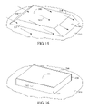
- FIG. 17 is a schematic view of the transducer of FIG. 14 from the trailing end, showing the coils and the second yoke, which tapers to adjoin the narrow trailing pole-tip.
- FIG. 18 is a cutaway cross-sectional view of an embodiment of a head like that of FIG. 14 but having a sloping side of a second yoke adjoining the pole-tip.
- FIG. 19 is a cutaway cross-sectional view of an embodiment of a head like that of FIG. 18 but having a level side of a second yoke adjoining the pole-tip distal to a write gap.
- FIG. 20 is a cutaway cross-sectional view of an embodiment of a head like that of FIG. 19 but having a flat second yoke adjoining the pole-tip distal to a write gap.
- FIG. 21 is a cutaway cross-sectional view of an embodiment of a head like that of FIG. 20 but having a relieved media-facing surface with pole-tips that project slightly compared to the yokes and MR sensor.
- FIG. 22 is a cutaway cross-sectional view of the head of FIG. 20 interacting with a media such as a rigid magnetic disk.
- FIG. 2 is a cutaway view of a media-facing side of a head 100 in accordance with the present invention focusing on a transducer 102 having a narrow trailing pole-tip 105 .
- the pole-tip may have a width (W 1 ) that is 0.3 ⁇ m or less and a length (L 1 ) that is about 1 ⁇ m–2 ⁇ m, although either the width or length of the pole-tip can be varied by a factor of two or more.
- a length-to-width (L 1 /W 1 ) aspect ratio for pole-tip 105 may exceed six and may approach infinity.
- pole-tip 105 For near-term products, length-to-width aspect ratios for pole-tip 105 may be in a range between about six and one-hundred. As described in detail below, the pole-tip 105 has been deposited as a layer on a substantially vertical sidewall, and so the width W 1 of the pole-tip is essentially the thickness of the layer. Such a pole-tip layer 105 can be made as thin as a few atoms in thickness, so that W 1 is less than 20 ⁇ , although such an extremely narrow pole-tip is not currently necessary.
- the pole-tip may be made of high magnetic saturation (high B s ) materials, including iron films or laminates, primarily iron NiFe (e.g., Ni 45 Fe 55 ), Sendust (AlSiFe), or other known high B s compounds.
- Cobalt-based alloys such as CoZrNb, CoZrNb and CoZrRe, nitrogen doped iron films, such as compounds containing FeNX, where X can be Rh, Ta or Al, or compounds containing FeCo also may be used to form a high B s pole-tip.
- pole-tip 105 of high B s materials can avoid magnetic saturation despite the pole-tip having a much smaller cross-sectional area than most of the remainder of the magnetic yoke, not shown in this figure.
- the pole-tip 105 can also be laminated to provide for extremely high frequency operation without deleterious eddy currents.
- the transducer 102 is formed in a series of layers on a substrate 107 , beginning with a first magnetically permeable shield layer 110 .
- the shield may have a thickness of about 2 ⁇ m and a width that is several times larger than its thickness.
- a first amagnetic (non-ferromagnetic), electrically insulating read gap layer is formed on the first shield 110 to separate the first shield from a MR sensor 112 .
- a second amagnetic, electrically insulating read gap layer is formed on the MR sensor 112 to separate the MR sensor from a second shield 115 .
- the read gap layers may have a thickness in a range between about 50 ⁇ and 400 ⁇ , and may be formed of a variety of materials including Alumina, DLC, SiC and SiO 2 .
- Second shield 115 also serves as a first pole-tip of a magnetically permeable yoke that encircles a conductive coil, not shown in this figure, the first pole-tip 115 being separated from the trailing pole-tip 105 by an amagnetic, electrically insulating recording gap 118 , which may have a thickness on the order of 200 nm.
- the trailing pole-tip 105 is encased with an amagnetic, electrically insulating layer defining a trailing end 138 of head 100 .
- reading of signals is performed by the MR sensor 112
- writing of patterns on the media is performed by magnetic flux spreading out from the gap 118 while travelling between the pole-tips 105 and 115 .
- the width W 1 of the trailing pole-tip 105 corresponds to a width of a data track recorded on the medium, and may be more or less than the gap 118 between the pole-tips 105 and 115 .
- the MR sensor 112 may have a width that is less than W 1 , and a thickness that is even less.
- FIG. 3 is a cutaway cross-sectional view of the head 100 of FIG. 2 , focusing on the transducer 102 portion of the head.
- a protective overcoat 106 made of a form of diamond-like carbon (DLC), such as tetrahedral amorphous carbon (ta-C), or silicon carbide (SiC), or other known materials may be disposed on a media facing surface 108 of the head and evident in FIG. 3 , but is substantially transparent and so not shown in FIG. 2 .
- DLC diamond-like carbon
- ta-C tetrahedral amorphous carbon
- SiC silicon carbide
- the head 100 is formed on a wafer substrate 107 , that may be made of alumina (Al 2 O 3 ), alumina titanium carbide (Al 2 O 3 -TiC), silicon (Si), silicon dioxide (SiO 2 ), silicon carbide (SiC) or other known materials, the head being mass-produced along with hundreds or thousands of other heads.
- a head may be formed on a magnetically permeable substrate, such as ferrite, which essentially becomes a first yoke layer.
- a leading and trailing pole-tip may be formed of high B s material, and may be formed prior to an optional sensor. It is also possible to form the head on a substrate that is later removed.
- the first magnetically permeable layer 110 is formed of a material such as Permalloy (Ni 80 Fe 20 ), which will function as a magnetic shield.
- the first shield layer 110 may be formed by first sputtering a seed layer of Permalloy, then masking an area to leave an aperture for the shield to be grown by electroplating, then removing the mask and finally removing the sputtered seed layer not covered by the electroplated layer, as is conventional.
- a first read gap layer of an amagnetic, electrically insulating material such as Alumina, SiO 2 or DLC is then formed, on top of which the magnetoresistive (MR) sensor 112 is formed.
- the MR sensor 112 may be an anisotropic magnetoresistive (AMR) sensor, spin valve (SV) sensor, giant magnetoresistive (GMR) sensor, or other known sensors, the details of which are known in the art and omitted here for conciseness.
- AMR anisotropic magnetoresistive
- SV spin valve
- GMR giant magnetoresistive
- the MR sensor may be composed of a strata of layers having thicknesses ranging between about 4 ⁇ and 100 ⁇ , so that the MR sensor formed by the strata has a thickness less than 500 ⁇ .
- the MR sensor 2 is depicted with a similar width as the width W 1 of the narrow trailing pole-tip, which may for example be 0.2 ⁇ m (2000 ⁇ ) or less, but the MR sensor may alternatively have a width that is less than or greater than that of the pole-tip 105 . Even for the case in which the MR sensor is trimmed to have a track width of 0.1 ⁇ m (1000 ⁇ ) or less, that width may still be substantially larger than the thickness of the MR sensor which, as mentioned above, may be less than 500 ⁇ thick.
- a back gap and a second read gap of electrically insulating, amagnetic materials such as alumina, silicon dioxide or diamond-like carbon are also formed, which combine with the first read gap to form a layer 114 of electrically insulating, amagnetic material encasing MR sensor 112 .
- the first yoke layer 115 of magnetically permeable material such as Permalloy is then formed for transducer 102 , layer 115 also serving as a shield for the MR sensor 112 in this embodiment of a merged head.
- transducers may employ a narrow pole-tip according to the present invention, including piggyback heads, planar heads, heads removed from a substrate, heads having an integrated slider and suspension, heads having an optical sensor, heads with an MR sensor formed after the trailing pole-tip, and inductive heads without an additional sensor.
- piggyback heads planar heads
- heads removed from a substrate heads having an integrated slider and suspension
- heads having an optical sensor heads having an optical sensor
- heads with an MR sensor formed after the trailing pole-tip and inductive heads without an additional sensor.
- the novel pole-tip 105 may be formed either before or after formation of an electrically conductive coil 120 for the transducer 102 .
- An advantage of the present invention is that a narrow pole-tip can be formed somewhat independently of a magnetically permeable yoke that substantially encircles an electrically conductive coil. Note also that describing a magnetically permeable yoke as substantially encircling an electrically conductive coil is meant to represent an inductive transducer, for which the coil may have a single turn or many and which may have a majority of its length not encircled by the yoke. For the case in which the pole-tip 105 is formed after formation of the coil, the pole-tip may be formed prior or subsequent to formation of a second yoke layer for the transducer.
- FIG. 3 for example shows an embodiment in which the pole-tip 105 was formed subsequent to the coil 120 but prior to a second yoke layer 130 of magnetically permeable material such as Permalloy.
- an amagnetic, electrically insulating layer 113 is first formed that will provide the write gap, and which may provide a surface on top of which the conductive coil 120 is created.
- the coil may be formed by electroplating copper (Cu), gold (Au) or other conductive materials on a conductive seed layer through a mask that is then removed, after which the seed layer is removed.
- the coil 120 may then be surrounded by amagnetic, electrically insulating material such as Alumina, which can then be polished to essentially form layer 117 shown in FIG. 3 .
- Layer 117 may then be masked and etched to define edges 122 and 123 , and the narrow pole-tip 105 can then be formed adjacent edge 122 .
- FIG. 4 depicts some steps in the formation of the narrow trailing pole-tip 105 that was shown in FIG. 2 and FIG. 3 , viewed at a cross-section located close to what will become the media-facing surface.
- a layer 119 of amagnetic, electrically insulating material which surrounds yoke layer 115 is apparent, with layers 115 and 119 polished to form a smooth surface for gap layer 113 .
- a base layer 140 is formed on the insulating layer 113 , the base layer having a substantially vertical sidewall 142 disposed adjacent the yoke layer 115 .
- the base layer 140 for example may be a photoresist layer that has been developed to create sidewall 142 .
- the base layer 140 may be a ceramic layer or other hard, amagnetic, electrically insulating layer, such as Alumina, SiO 2 or Si 3 N 4 , which has been etched, milled or ablated to create sidewall 142 .
- a layer 144 of magnetically permeable material which will form the narrow pole-tip is then grown on the base layer 140 , sidewall 142 and the exposed portion of insulating layer 113 .
- the magnetically permeable material layer 144 may be formed in an evacuated chamber from gas, plasma or beams of ions, for example by chemical vapor deposition (CVD), plasma enhanced chemical vapor deposition (PECVD) with or without a collimator, ion beam deposition (IBD) or sputtering (RF or DC), which allows the layer 144 to be as thin as a few nanometers or less in thickness.
- CVD chemical vapor deposition
- PECVD plasma enhanced chemical vapor deposition
- IBD ion beam deposition
- RF or DC sputtering
- Layer 144 may be formed in the presence of a magnetic field, either during deposition or in a post deposition anneal, that helps to provide an easy axis of magnetization to the magnetic material, for example along the width W 1 or length L 1 direction of pole-tip 105 , shown in FIG. 2 .
- Layer 144 may be formed may be formed of Permalloy or materials having a higher B s than Permalloy.
- Sputtering and other vacuum-deposition techniques may provide different material characteristics to the pole-tip than conventional formation by electroplating in a liquid solution.
- the sputtered layer 144 may be denser than a similar electroplated layer, and is free of residual impurities, such as chlorine, sulfur and carbon-based molecules that may otherwise be left from an electroplating solution. These impurities can promote corrosion of the head and may also degrade magnetic performance characteristics of conventional pole-tips, for example by reducing permeability and B s . Eddy currents can also be reduced with vacuum-deposited pole-tip materials, allowing higher frequency operation.
- Permalloy is easy to electroplate, some materials having a higher B s than Permalloy may be difficult to form by electroplating, limiting the magnetic performance of conventional pole-tips.
- compounds containing refractory metals such as elements found in columns IVB–VIB of the periodic table (e.g., Zr, Ta and Cr), may be difficult to electroplate but may be formed by sputtering in accordance with the present invention.
- Deposition of the magnetically permeable material may occur at an angle from normal to the wafer surface, as shown by arrows 146 , covering sidewall 142 .
- the deposition angle may range between zero and about eighty degrees, and may be static or rotating, depending in part whether upon whether the transducers laid out on the wafer surface have identical adjacent structures or mirror-image layouts.
- the sputtering source may be shut off during rotation of the wafer when neither sidewall is facing the sputtering source.
- the sputtered layer 144 has a growth morphology that results from growing outward from the base and self-shadowing from the angled deposition.
- This growth direction can be controlled with process parameters such as sputtering angle, and typically falls in a range between normal to the surface upon which the film is being grown and 70° to that normal.
- This sputtered structure of layer 144 can be observed with a transmission electron microscope (TEM) and differentiated from an electroplated layer having a similar chemical composition.
- TEM transmission electron microscope
- the growth morphology of the sputtered layer can also help to orient the easy axis of magnetization of layer 144 .
- FIG. 5 shows a plurality of magnetically permeable layers 146 and 148 formed on base 140 and separated by an amagnetic, electrically insulative layer 147 , which may be used for a pole-tip affording extremely high frequency operation without harm from eddy currents.
- the amagnetic, electrically insulative layer 147 may be formed of Alumina or SiO 2 , for example, and may be deposited at a similar or different angle than that of one or both of the magnetically permeable layers 146 and 148 .
- FIG. 6 shows that portions of layer 144 that lie atop the base 140 and insulating layer 113 have been removed, for example by ion beam milling or other anisotropic removal as indicated by arrows 150 , leaving the vertical portion of layer 144 adjoining sidewall 142 .
- the beam direction 150 should be within about ten degrees from normal to the wafer surface, and may be static or rotating.
- FIG. 7 depicts an embodiment in which base layer 140 can be selectively removed, such as when the base is formed of photoresist.
- chemical or other removal of the base layer can leave the narrow vertical portion of the magnetically permeable material layer 144 standing naked atop the insulating layer 113 .
- the insulating layer 113 is to become the amagnetic gap 118 of FIG. 3
- magnetically permeable layer 144 is to become the narrow pole-tip 105 of FIG. 3 , with the novel pole-tip layer oriented substantially perpendicular to the gap layer.
- FIG. 8 depicts an embodiment in which base layer 140 has been formed of a ceramic layer or other hard, amagnetic, electrically insulating layer, such as Alumina, and remains intact adjacent magnetic layer 144 .
- a similar hard, amagnetic, electrically insulating layer 148 such as Alumina may be formed on the other side of the perpendicular pole-tip layer 144 , encasing that layer 144 .
- the hard layers 144 and 148 are then polished, such as by a chemical-mechanical polish, to form a flat surface, trimming the magnetic layer 144 to form a pole-tip 105 , resulting in a structure similar to that shown in FIG. 9 .
- FIG. 9 shows that the perpendicular pole-tip layer 144 of FIG. 7 has been surrounded by hard, amagnetic, electrically insulating material that was then planarized, such as by mechanical or chemical-mechanical polishing (CMP), to form a flat surface for layer 152 and to define the length of pole-tip 225 .
- CMP chemical-mechanical polishing
- a second magnetically permeable yoke layer 130 is formed by sputtering and/or electroplating.
- the mask through which the yoke was formed has an edge 132 that overlaps the pole-tip but does not extend as close to the media-facing surface as the pole-tip.
- the yoke layer 130 extends as close to the media-facing surface as the pole-tip 105 , forming a T-shaped pole-tip when viewed from the media-facing surface.
- a layer 155 of hard, amagnetic, electrially insulating material such as Alumina or DLC is formed over and around the second yoke layer 130 , and after planarization of those layers a small portion of layer 155 is disposed between the yoke layer 130 and the overcoat 106 .
- Another layer 135 of hard, amagnetic, electrically insulating material such as Alumina or DLC is formed atop the planarized second yoke layer 130 and surrounding layer 155 , protecting the transducer 102 on a trailing end 138 of the head 100 . After dicing the wafer into rows each containing multiple transducers such as transducer 102 , the rows are rotated ninety degrees and a protective overcoat 106 is then deposited while forming the media-facing surface 108 .
- FIG. 10 shows another embodiment of a head 200 in which a trailing pole-tip 205 for a transducer 202 is formed subsequent to formation of a coil layer 220 but prior to formation of a second yoke layer 230 .
- the head 200 includes a substrate 207 , first shield layer 210 , MR sensor 212 encased in amagnetic, electrically insulating material 214 , and a second shield layer 215 that also serves as a first yoke.
- a first magnetically permeable pole-tip 216 Adjoining the first yoke layer 215 in this embodiment, however, a first magnetically permeable pole-tip 216 is formed, surrounded by amagnetic, electrically insulating material 217 .
- This leading pole-tip 216 may be formed by conventional techniques of electroplating through a mask and then ion milling to remove a seed layer and to optionally thin the pedestal.
- a closure pedestal 219 made of magnetically permeable material may be formed at the same time as the leading pole-tip 216 , although it is known that a magnetically permeable loop can be formed by the yokes and pole-tips despite small discontinuities in magnetically permeable material.
- Pole-tip 216 may help to focus magnetic flux transferred to and from the trailing pole-tip 205 .
- the leading pole-tip 205 may be wider than the trailing pole-tip.
- the leading pole-tip may be formed by overetching of the trailing pole-tip 205 that removes portions of the gap layer 213 and first yoke 215 not covered by trailing pole-tip 205 , aligning the pole-tips.
- a first protective coating may first be deposited on the trailing pole-tip before overetching, and a second protective coating deposited on the first yoke 215 after the overetching, to allow removal of possible redeposited magnetic material adjacent the gap, for example with an angular IBE.
- the leading pole-tip 216 may also be formed on a sidewall in a layer aligned with the trailing pole-tip, much as described above with regard to FIGS. 4–9 .
- the closure pedestal 219 may be formed before or after the leading pole-tip 216 for this embodiment.
- a conductive coil 220 is formed by sputtering, electroplating and ion milling on the surface of the insulating layer 217 , and then an amagnetic, electrically insulating layer 213 is formed, which will become the write gap 218 .
- FIG. 11 shows a cutaway perspective view of a deposition step in creating the trailing pole-tip 205 of FIG. 10 .
- a photoresist mask layer 240 blankets the amagnetic, electrically insulating layer 213 , except for an aperture having a substantially vertical sidewall 244 upon which the pole-tip 205 is to be formed. For clarity, only the layers immediately beneath the insulating layer 213 , consisting of the first pole-tip 216 and insulating layer 217 , are shown in this figure.
- a magnetically permeable, high B s material is sputtered at a static angle depicted by arrows 242 , coating wall 244 as well as a major surface 248 of resist layer 240 , but avoids a slightly shadowed wall 246 adjacent to coils 220 , not shown in this figure.
- An IBE directed substantially normal to the major surface then removes the magnetically permeable, high B s material from the photoresist surface and from the surface of layer 213 exposed through the mask, leaving a layer of high B s material adjoining wall 244 , much as shown in FIG. 6 .
- the mask is then removed, leaving an isolated layer of high B s material that is to form pole-tip 205 , similar to that shown in FIG, 7 .
- the isolated layer of high B s material is then encased in amagnetic, electrically insulating material 222 and then polished to expose the trailing pole-tip 205 for connection with a second yoke layer 230 .
- the second yoke layer 230 extends to meet the closure pedestal 219 or, in an alternative embodiment not shown in this figure, another closure pedestal may first be formed atop pedestal 219 .
- a protective coating 233 is then formed at a trailing end 235 of head 200 .
- this embodiment shows the second yoke layer 230 adjoining a protective overcoat that forms a media-facing surface 208 , the second yoke layer may instead overlap part of the pole-tip 205 and terminate prior to the overcoat 206 , similar to the second yoke shown in FIG. 10 .
- FIG. 12 is a cutaway view of a media-facing side of the head 200 of FIG. 10 focusing on the transducer 202 .
- the first yoke 215 and leading pole-tip 216 form a T-shaped structure, as do the second yoke 230 and trailing pole-tip 205 , separated by the write gap 218 .
- a leading end of the head is not shown in this figure for clarity but is located opposite the trailing end 235 , and generally encounters a portion of media passing adjacent the head immediately prior to the media portion passing by the remainder of the head, with the media portion last encountering the trailing end before moving away from the head.
- FIG. 13 shows an embodiment of a head 250 that is formed much as described regarding FIG. 10 prior to the formation of a conductive coil, and so is not renumbered for like elements.
- a trailing pole-tip 255 is formed subsequent to formation of a second yoke layer 268 .
- a coil 257 is formed on the surface of amagnetic, electrically insulating layer 217 that was described with regard to FIG. 10 .
- Another amagnetic, electrically insulating layer 260 such as photoresist is then formed on and around the coil 257 , and reflowed to create a sloping side 262 adjacent the pole-tip 255 .
- a second yoke 268 may then formed by sputtering a film of Permalloy, masking an area to leave an aperture for the yoke to be grown by electroplating, removing the mask and then removing the sputtered film not covered by the electroplated layer.
- the mask creates an edge 270 to the yoke adjacent to where the trailing pole-tip 255 is to be formed.
- the pole-tip is then created much as described above with respect to FIGS. 4–9 , and then encased in a protective layer 272 of amagnetic, electrically insulating material along a trailing end 275 of the head 250 .
- the base layer upon which the pole-tip is formed may be made of a resist that is spun so that it does not cover a plateau 274 of the second yoke 268 , and the high B s material that forms the pole-tip may be deposited at an angle that avoids shadowing by edge 270 .
- another protective overcoat 277 is formed on a media-facing surface 280 .
- FIG. 14 depicts a head 300 including a transducer having a narrow trailing pole-tip 305 that is formed prior to forming a coil layer 320 .
- head 300 includes a wafer substrate 307 , a first magnetically permeable shield layer 310 , a MR sensor 312 encased in an amagnetic, electrically insulating layer 314 and a second shield that also functions as a first yoke layer 315 .
- a leading pole-tip 316 and a closure pedestal 319 are formed of magnetically permeable material such as Permalloy, the pole-tip and pedestal separated by an amagnetic, electrically insulating layer 317 .
- an amagnetic, electrically insulating layer 313 of material such as alumina, silicon dioxide or diamond-like carbon is formed, creating a recording or write gap 318 between the pole-tips 305 and 316 .
- an amagnetic, electrically insulating layer 313 of material such as alumina, silicon dioxide or diamond-like carbon is formed, creating a recording or write gap 318 between the pole-tips 305 and 316 .
- the narrow, magnetically permeable trailing pole-tip 305 may be formed as described previously with regard to FIGS. 4–9 or FIG. 11 , or as shown in FIG. 15 and described below.
- FIG. 15 is a cutaway perspective view of a base 350 that serves as a template for creating the narrow, magnetically permeable trailing pole-tip, the base disposed atop amagnetic layer 313 .
- the base 350 in this embodiment is a raised plateau that may be formed for example of photoresist that has been developed to have a pair of substantially vertical sides 353 and 358 , and a pair of sloping sides 354 and 355 .
- the substantially vertical side 353 may be an edge upon which the trailing pole-tip is deposited, and for an embodiment in which transducers are formed on the wafer surface in mirror-image patterns, an oppositely disposed, substantially vertical side 358 may be an edge upon which another trailing pole-tip is deposited.
- the sloping sides 354 and 355 may be created with a developing mask that transmits a graded intensity of light during development, such as a mask having opaque bars that vary in spacing or width.
- a magnetically permeable, high B s material may be sputtered on the base 350 at an angle from normal to the wafer surface, as shown by arrows 357 , covering sides 353 and 354 .
- the deposition angle may range between zero and about eighty degrees, and may be static or rotating, depending in part whether upon whether the transducers laid out on the wafer surface have identical adjacent structures or mirror-image layouts.
- sides 355 and 358 are also covered with the magnetically permeable material.
- a subsequent anisotropic removal process such as a substantially vertical IBE, can remove the magnetically permeable material from sides 354 and 355 without significantly thinning layers 362 and 364 of the material deposited on sides 353 and 358 , respectively. Layers 362 and 364 may then become trailing pole-tips for adjacent transducers being formed on a wafer surface.
- the conductive coil layer 320 may be formed by electroplating through a mask atop a conductive seed layer, with the seed layer then removed from between the coils.
- An amagnetic, electrically insulating layer 322 is then formed surrounding the coils 320 , and may be reflowed to create a sloping side adjacent the pole-tip 305 .
- a second yoke layer 330 is then formed by depositing a seed layer, then electroplating through a mask and then removing the seed layer not covered by the electroplated yoke.
- a protective layer 333 is then formed on what will become a trailing end 335 for the head 300 . The wafer is then diced and a protective coating 306 may be formed on what will become a media-facing surface 308 for the head.
- FIG. 17 shows a view of the transducer 302 from the trailing end, which for clarity only shows the active components formed over the amagnetic layer 313 .
- the coils 320 wind around between the amagnetic layer 313 and the second yoke 330 , which tapers to adjoin the narrow trailing pole-tip 305 .
- FIG. 18 shows an embodiment of a head 370 that is formed like that described regarding FIG. 14 prior to surrounding a conductive coil 372 with an amagnetic, electrically insulating material 373 , and so is not renumbered for like elements.
- the amagnetic, electrically insulating layer 373 may be reflowed to cover most of the trailing pole-tip 305 , creating a sloping side 383 adjacent the pole-tip 305 while leaving that pole-tip partially exposed.
- a second yoke 388 is then electroplated that covers the exposed portion of the pole-tip, the yoke tapered and sloping to provide a maximum flux intensity adjacent the write gap 318 .
- FIG. 19 shows an embodiment of a head 400 that is formed like that described regarding FIG. 18 prior to surrounding the conductive coil 372 with an amagnetic, electrically insulating material 403 , and so is not renumbered for like elements.
- the pole-tip 305 is encased in an amagnetic, electrically insulating material, not shown in this cross-sectional view, leaving a surface of the pole-tip exposed distal to the gap 318 .
- An amagnetic, electrically insulating layer 403 such as photoresist is then formed, surrounding and covering the coil layer 372 and exposed surface of pole-tip 305 .
- the part of layer 403 covering the pole-tip 305 and closure pedestal 319 is then removed, and a second yoke 408 is then electroplated that covers the exposed portion of the pole-tip 305 and pedestal 319 .
- the second yoke 408 terminates further from the media-facing surface 308 than does the trailing pole-tip 305 .
- FIG. 20 shows an embodiment of a head 450 with a transducer 452 that is formed like that described regarding FIG. 20 up to forming the leading pedestal 316 and closure pedestal 319 .
- An amagnetic, electrically insulating layer 453 is then formed that is to provide a write gap 458 .
- a trailing pole-tip 455 is then formed as described with regard to FIGS. 4–9 , FIG. 11 or FIG. 15 .
- a conductive coil 457 is then formed, and then surrounded with an amagnetic, electrically insulating material 464 that also covers the trailing pole-tip 455 .
- the insulating material 464 is then planarized to expose the trailing pole-tip 455 and trimmed to expose closure pedestal 319 .
- a second magnetically permeable yoke 466 is then formed atop the insulating layer 464 , the pole-tip 455 and the pedestal 319 .
- the coil layer may be made thinner so that the second yoke layer 466 can be essentially coplanar with the pole-tip 455 , adjoining the pole-tip distal to a media-facing surface 488 rather than adjoining the pole-tip distal to the gap layer 453 .
- a protective coating 470 is then formed on a trailing end 474 of the head. After separating the head 450 from other heads of the wafer substrate 307 , another protective coating 480 may be formed on the media-facing surface 488 .
- FIG. 21 shows a head 500 like that of FIG. 20 , except that a media-facing surface 505 has been relieved so that pole-tips 316 and 455 protrude compared to yokes 315 and 466 , shield 310 and MR sensor 312 .
- This relative protrusion of the pole-tips 316 and 455 decreases fringe fields of the yokes 315 and 466 that may otherwise be felt by a media with which the head communicates.
- Recession of the MR sensor 312 relative to the pole-tips helps to avoid damage to the MR sensor and false signals from thermal asperities that may otherwise be caused by high-speed contact with the media.
- the protrusion of the pole-tips 316 and 455 relative to the yokes 315 and 466 and MR sensor 312 may range between about 40 ⁇ and 0.1 ⁇ m, and may be different amounts for the first yoke 315 , second yoke 466 and MR sensor 312 .
- Relieving of the media-facing surface 505 may occur after the head 500 has been diced into rows and rotated to form an air-bearing or media-contacting surface. After relieving the media-facing surface 505 a protective overcoat 510 may be applied to some or all of that surface. This approach may be used with any of the above-described heads, as well as other embodiments not listed above.
- FIG. 22 shows the head 500 of FIG. 21 interacting with a media 550 , such as a rigid or flexible magnetic disk or tape, or magneto-optical disk or tape for the case in which the head has an optical rather than an MR sensor.
- a media 550 such as a rigid or flexible magnetic disk or tape, or magneto-optical disk or tape for the case in which the head has an optical rather than an MR sensor.
- a wafer substrate 552 is shown that may be made of glass, SiC, aluminum, or any of a number of other materials known in the art.
- the substrate may or may not be roughened or patterned, as is known in the art, and is covered with an underlayer 555 that may provide adhesion and a desired structure for a media layer 560 formed on the underlayer.
- the media layer 560 may be a conventional cobalt (Co) based alloy, which may include elements such as chromium (Cr), platinum (Pt) and tantalum (Ta), for instance. Although a single media layer 560 is shown for conciseness, layer 560 may actually represent several layers as is known, and may be designed for longitudinal or perpendicular data storage.
- the underlayer 555 may include Cr, nickel aluminum (NiAl), magnesium oxide (MgO) or other materials known in the art, and may be formed of more than one layer.
- a thin layer 562 of DLC, ta-C, or SiC is formed, creating a dense, hard surface 565 for the disk 550 .
- the layer 562 may have a thickness in a range between about 8 ⁇ to 100 ⁇ , similar to that of head overcoat layer 510 .
- the disk 550 is moving relative to the head 500 in a direction shown by arrow 570 , while the head may be positioned over a single concentric data track of the disk or may be sweeping across the disk in a direction into or out of the paper of this cross-sectional drawing.
- the disk may be rotating at various speeds known in the art, so that the relative speed in the direction of arrow 570 may range between a few meters per second and well over ten meters per second.
- a layer of air or other ambient gas accompanies the rapidly spinning disk surface 565 and interacts with the media-facing surface 505 of the head 500 , causing the head in this embodiment to levitate slightly from the disk.
- the head may be designed to operate in occasional, frequent or continuous physical contact with the disk.
- the head surface 505 is separated from the disk surface 565 by a physical spacing that may range between several hundred angstroms and zero, with a preferred spacing of between about two hundred angstroms and about thirty angstroms.
- a lubricant including perfluorocarbon molecules or other known materials may be distributed on the disk surface 565 beneath the head.
Abstract
Description
Claims (43)
Priority Applications (1)
| Application Number | Priority Date | Filing Date | Title |
|---|---|---|---|
| US09/500,380 US7023658B1 (en) | 2000-02-08 | 2000-02-08 | Submicron track-width pole-tips for electromagnetic transducers |
Applications Claiming Priority (1)
| Application Number | Priority Date | Filing Date | Title |
|---|---|---|---|
| US09/500,380 US7023658B1 (en) | 2000-02-08 | 2000-02-08 | Submicron track-width pole-tips for electromagnetic transducers |
Publications (1)
| Publication Number | Publication Date |
|---|---|
| US7023658B1 true US7023658B1 (en) | 2006-04-04 |
Family
ID=36102018
Family Applications (1)
| Application Number | Title | Priority Date | Filing Date |
|---|---|---|---|
| US09/500,380 Expired - Fee Related US7023658B1 (en) | 2000-02-08 | 2000-02-08 | Submicron track-width pole-tips for electromagnetic transducers |
Country Status (1)
| Country | Link |
|---|---|
| US (1) | US7023658B1 (en) |
Cited By (148)
| Publication number | Priority date | Publication date | Assignee | Title |
|---|---|---|---|---|
| US20020057525A1 (en) * | 2000-05-11 | 2002-05-16 | Van Zon Joannes Baptist Adrianus Dionisius | Method of manufacturing a magnetic element |
| US20060152849A1 (en) * | 2003-07-29 | 2006-07-13 | Hsiao Wen-Chien D | Magnetic head having a write coil structure with a reduced electrical resistance for reducing thermal protrusion |
| US20060171071A1 (en) * | 2005-01-31 | 2006-08-03 | Alps Electric Co., Ltd. | Soft magnetic film and thin-film magnetic head using the same |
| US20060273066A1 (en) * | 2005-06-01 | 2006-12-07 | Hitachi Global Storage Technologies | Method for manufacturing a magnetic sensor having an ultra-narrow track width |
| US7289297B1 (en) * | 2004-06-07 | 2007-10-30 | Storage Technology Corporation | Multilayered ferromagnetic laminate having alternating cobalt alloy and iron-nitrogen alloy films for use with magnetic heads |
| US7508624B1 (en) * | 2003-08-01 | 2009-03-24 | Lauer Mark A | Transducers for perpendicular recording with write pole tip angled toward media |
| US20090154015A1 (en) * | 2007-12-16 | 2009-06-18 | Amanda Baer | Magnetic write pole fabrication |
| US20090237837A1 (en) * | 2008-03-19 | 2009-09-24 | Seagate Technology Llc | Magnetic recording head |
| US8136225B1 (en) | 2008-05-15 | 2012-03-20 | Western Digital (Fremont), Llc | Method and system for providing a perpendicular magnetic recording head |
| US8166632B1 (en) | 2008-03-28 | 2012-05-01 | Western Digital (Fremont), Llc | Method for providing a perpendicular magnetic recording (PMR) transducer |
| US8793866B1 (en) | 2007-12-19 | 2014-08-05 | Western Digital (Fremont), Llc | Method for providing a perpendicular magnetic recording head |
| US8830628B1 (en) | 2009-02-23 | 2014-09-09 | Western Digital (Fremont), Llc | Method and system for providing a perpendicular magnetic recording head |
| US8879207B1 (en) | 2011-12-20 | 2014-11-04 | Western Digital (Fremont), Llc | Method for providing a side shield for a magnetic recording transducer using an air bridge |
| US8883017B1 (en) | 2013-03-12 | 2014-11-11 | Western Digital (Fremont), Llc | Method and system for providing a read transducer having seamless interfaces |
| US8917581B1 (en) | 2013-12-18 | 2014-12-23 | Western Digital Technologies, Inc. | Self-anneal process for a near field transducer and chimney in a hard disk drive assembly |
| US8923102B1 (en) | 2013-07-16 | 2014-12-30 | Western Digital (Fremont), Llc | Optical grating coupling for interferometric waveguides in heat assisted magnetic recording heads |
| US8947985B1 (en) | 2013-07-16 | 2015-02-03 | Western Digital (Fremont), Llc | Heat assisted magnetic recording transducers having a recessed pole |
| US8953422B1 (en) | 2014-06-10 | 2015-02-10 | Western Digital (Fremont), Llc | Near field transducer using dielectric waveguide core with fine ridge feature |
| US8958272B1 (en) | 2014-06-10 | 2015-02-17 | Western Digital (Fremont), Llc | Interfering near field transducer for energy assisted magnetic recording |
| US8970988B1 (en) | 2013-12-31 | 2015-03-03 | Western Digital (Fremont), Llc | Electric gaps and method for making electric gaps for multiple sensor arrays |
| US8971160B1 (en) | 2013-12-19 | 2015-03-03 | Western Digital (Fremont), Llc | Near field transducer with high refractive index pin for heat assisted magnetic recording |
| US8976635B1 (en) | 2014-06-10 | 2015-03-10 | Western Digital (Fremont), Llc | Near field transducer driven by a transverse electric waveguide for energy assisted magnetic recording |
| US8982508B1 (en) | 2011-10-31 | 2015-03-17 | Western Digital (Fremont), Llc | Method for providing a side shield for a magnetic recording transducer |
| US8980109B1 (en) | 2012-12-11 | 2015-03-17 | Western Digital (Fremont), Llc | Method for providing a magnetic recording transducer using a combined main pole and side shield CMP for a wraparound shield scheme |
| US8988812B1 (en) | 2013-11-27 | 2015-03-24 | Western Digital (Fremont), Llc | Multi-sensor array configuration for a two-dimensional magnetic recording (TDMR) operation |
| US8988825B1 (en) | 2014-02-28 | 2015-03-24 | Western Digital (Fremont, LLC | Method for fabricating a magnetic writer having half-side shields |
| US8984740B1 (en) | 2012-11-30 | 2015-03-24 | Western Digital (Fremont), Llc | Process for providing a magnetic recording transducer having a smooth magnetic seed layer |
| US8995087B1 (en) | 2006-11-29 | 2015-03-31 | Western Digital (Fremont), Llc | Perpendicular magnetic recording write head having a wrap around shield |
| US8993217B1 (en) | 2013-04-04 | 2015-03-31 | Western Digital (Fremont), Llc | Double exposure technique for high resolution disk imaging |
| US9001467B1 (en) | 2014-03-05 | 2015-04-07 | Western Digital (Fremont), Llc | Method for fabricating side shields in a magnetic writer |
| US9001628B1 (en) | 2013-12-16 | 2015-04-07 | Western Digital (Fremont), Llc | Assistant waveguides for evaluating main waveguide coupling efficiency and diode laser alignment tolerances for hard disk |
| US8997832B1 (en) | 2010-11-23 | 2015-04-07 | Western Digital (Fremont), Llc | Method of fabricating micrometer scale components |
| US9007725B1 (en) | 2014-10-07 | 2015-04-14 | Western Digital (Fremont), Llc | Sensor with positive coupling between dual ferromagnetic free layer laminates |
| US9007879B1 (en) | 2014-06-10 | 2015-04-14 | Western Digital (Fremont), Llc | Interfering near field transducer having a wide metal bar feature for energy assisted magnetic recording |
| US9007719B1 (en) | 2013-10-23 | 2015-04-14 | Western Digital (Fremont), Llc | Systems and methods for using double mask techniques to achieve very small features |
| US9013836B1 (en) | 2013-04-02 | 2015-04-21 | Western Digital (Fremont), Llc | Method and system for providing an antiferromagnetically coupled return pole |
| US9042051B2 (en) | 2013-08-15 | 2015-05-26 | Western Digital (Fremont), Llc | Gradient write gap for perpendicular magnetic recording writer |
| US9042057B1 (en) | 2013-01-09 | 2015-05-26 | Western Digital (Fremont), Llc | Methods for providing magnetic storage elements with high magneto-resistance using Heusler alloys |
| US9042052B1 (en) | 2014-06-23 | 2015-05-26 | Western Digital (Fremont), Llc | Magnetic writer having a partially shunted coil |
| US9042058B1 (en) | 2013-10-17 | 2015-05-26 | Western Digital Technologies, Inc. | Shield designed for middle shields in a multiple sensor array |
| US9042208B1 (en) | 2013-03-11 | 2015-05-26 | Western Digital Technologies, Inc. | Disk drive measuring fly height by applying a bias voltage to an electrically insulated write component of a head |
| US9053735B1 (en) | 2014-06-20 | 2015-06-09 | Western Digital (Fremont), Llc | Method for fabricating a magnetic writer using a full-film metal planarization |
| US9065043B1 (en) | 2012-06-29 | 2015-06-23 | Western Digital (Fremont), Llc | Tunnel magnetoresistance read head with narrow shield-to-shield spacing |
| US9064528B1 (en) | 2013-05-17 | 2015-06-23 | Western Digital Technologies, Inc. | Interferometric waveguide usable in shingled heat assisted magnetic recording in the absence of a near-field transducer |
| US9064527B1 (en) | 2013-04-12 | 2015-06-23 | Western Digital (Fremont), Llc | High order tapered waveguide for use in a heat assisted magnetic recording head |
| US9064507B1 (en) | 2009-07-31 | 2015-06-23 | Western Digital (Fremont), Llc | Magnetic etch-stop layer for magnetoresistive read heads |
| US9070381B1 (en) | 2013-04-12 | 2015-06-30 | Western Digital (Fremont), Llc | Magnetic recording read transducer having a laminated free layer |
| US9082423B1 (en) | 2013-12-18 | 2015-07-14 | Western Digital (Fremont), Llc | Magnetic recording write transducer having an improved trailing surface profile |
| US20150199984A1 (en) * | 2012-08-31 | 2015-07-16 | International Business Machines Corporation | Magnetic recording head having protected reader sensors and near zero recessed write poles |
| US9087534B1 (en) | 2011-12-20 | 2015-07-21 | Western Digital (Fremont), Llc | Method and system for providing a read transducer having soft and hard magnetic bias structures |
| US9087527B1 (en) | 2014-10-28 | 2015-07-21 | Western Digital (Fremont), Llc | Apparatus and method for middle shield connection in magnetic recording transducers |
| US9093639B2 (en) | 2012-02-21 | 2015-07-28 | Western Digital (Fremont), Llc | Methods for manufacturing a magnetoresistive structure utilizing heating and cooling |
| US9104107B1 (en) | 2013-04-03 | 2015-08-11 | Western Digital (Fremont), Llc | DUV photoresist process |
| US9111564B1 (en) | 2013-04-02 | 2015-08-18 | Western Digital (Fremont), Llc | Magnetic recording writer having a main pole with multiple flare angles |
| US9111558B1 (en) | 2014-03-14 | 2015-08-18 | Western Digital (Fremont), Llc | System and method of diffractive focusing of light in a waveguide |
| US9111550B1 (en) | 2014-12-04 | 2015-08-18 | Western Digital (Fremont), Llc | Write transducer having a magnetic buffer layer spaced between a side shield and a write pole by non-magnetic layers |
| US20150235662A1 (en) * | 2012-08-31 | 2015-08-20 | International Business Machines Corporation | Magnetic recording head having protected reader sensors and near zero recession writer poles |
| US9123362B1 (en) | 2011-03-22 | 2015-09-01 | Western Digital (Fremont), Llc | Methods for assembling an electrically assisted magnetic recording (EAMR) head |
| US9123359B1 (en) | 2010-12-22 | 2015-09-01 | Western Digital (Fremont), Llc | Magnetic recording transducer with sputtered antiferromagnetic coupling trilayer between plated ferromagnetic shields and method of fabrication |
| US9123358B1 (en) | 2012-06-11 | 2015-09-01 | Western Digital (Fremont), Llc | Conformal high moment side shield seed layer for perpendicular magnetic recording writer |
| US9123374B1 (en) | 2015-02-12 | 2015-09-01 | Western Digital (Fremont), Llc | Heat assisted magnetic recording writer having an integrated polarization rotation plate |
| US9135937B1 (en) | 2014-05-09 | 2015-09-15 | Western Digital (Fremont), Llc | Current modulation on laser diode for energy assisted magnetic recording transducer |
| US9135930B1 (en) | 2014-03-06 | 2015-09-15 | Western Digital (Fremont), Llc | Method for fabricating a magnetic write pole using vacuum deposition |
| US9142233B1 (en) | 2014-02-28 | 2015-09-22 | Western Digital (Fremont), Llc | Heat assisted magnetic recording writer having a recessed pole |
| US9147404B1 (en) | 2015-03-31 | 2015-09-29 | Western Digital (Fremont), Llc | Method and system for providing a read transducer having a dual free layer |
| US9147408B1 (en) | 2013-12-19 | 2015-09-29 | Western Digital (Fremont), Llc | Heated AFM layer deposition and cooling process for TMR magnetic recording sensor with high pinning field |
| US9153255B1 (en) | 2014-03-05 | 2015-10-06 | Western Digital (Fremont), Llc | Method for fabricating a magnetic writer having an asymmetric gap and shields |
| US9183854B2 (en) | 2014-02-24 | 2015-11-10 | Western Digital (Fremont), Llc | Method to make interferometric taper waveguide for HAMR light delivery |
| US9190079B1 (en) | 2014-09-22 | 2015-11-17 | Western Digital (Fremont), Llc | Magnetic write pole having engineered radius of curvature and chisel angle profiles |
| US9190085B1 (en) | 2014-03-12 | 2015-11-17 | Western Digital (Fremont), Llc | Waveguide with reflective grating for localized energy intensity |
| US9194692B1 (en) | 2013-12-06 | 2015-11-24 | Western Digital (Fremont), Llc | Systems and methods for using white light interferometry to measure undercut of a bi-layer structure |
| US9202480B2 (en) | 2009-10-14 | 2015-12-01 | Western Digital (Fremont), LLC. | Double patterning hard mask for damascene perpendicular magnetic recording (PMR) writer |
| US9202493B1 (en) | 2014-02-28 | 2015-12-01 | Western Digital (Fremont), Llc | Method of making an ultra-sharp tip mode converter for a HAMR head |
| US9214169B1 (en) | 2014-06-20 | 2015-12-15 | Western Digital (Fremont), Llc | Magnetic recording read transducer having a laminated free layer |
| US9214172B2 (en) | 2013-10-23 | 2015-12-15 | Western Digital (Fremont), Llc | Method of manufacturing a magnetic read head |
| US9214165B1 (en) | 2014-12-18 | 2015-12-15 | Western Digital (Fremont), Llc | Magnetic writer having a gradient in saturation magnetization of the shields |
| US9213322B1 (en) | 2012-08-16 | 2015-12-15 | Western Digital (Fremont), Llc | Methods for providing run to run process control using a dynamic tuner |
| US9230565B1 (en) | 2014-06-24 | 2016-01-05 | Western Digital (Fremont), Llc | Magnetic shield for magnetic recording head |
| US9236560B1 (en) | 2014-12-08 | 2016-01-12 | Western Digital (Fremont), Llc | Spin transfer torque tunneling magnetoresistive device having a laminated free layer with perpendicular magnetic anisotropy |
| US9245562B1 (en) | 2015-03-30 | 2016-01-26 | Western Digital (Fremont), Llc | Magnetic recording writer with a composite main pole |
| US9245543B1 (en) | 2010-06-25 | 2016-01-26 | Western Digital (Fremont), Llc | Method for providing an energy assisted magnetic recording head having a laser integrally mounted to the slider |
| US9245545B1 (en) | 2013-04-12 | 2016-01-26 | Wester Digital (Fremont), Llc | Short yoke length coils for magnetic heads in disk drives |
| US9251813B1 (en) | 2009-04-19 | 2016-02-02 | Western Digital (Fremont), Llc | Method of making a magnetic recording head |
| US9263071B1 (en) | 2015-03-31 | 2016-02-16 | Western Digital (Fremont), Llc | Flat NFT for heat assisted magnetic recording |
| US9263067B1 (en) | 2013-05-29 | 2016-02-16 | Western Digital (Fremont), Llc | Process for making PMR writer with constant side wall angle |
| US9269382B1 (en) | 2012-06-29 | 2016-02-23 | Western Digital (Fremont), Llc | Method and system for providing a read transducer having improved pinning of the pinned layer at higher recording densities |
| US9275657B1 (en) | 2013-08-14 | 2016-03-01 | Western Digital (Fremont), Llc | Process for making PMR writer with non-conformal side gaps |
| US9280990B1 (en) | 2013-12-11 | 2016-03-08 | Western Digital (Fremont), Llc | Method for fabricating a magnetic writer using multiple etches |
| US9286919B1 (en) | 2014-12-17 | 2016-03-15 | Western Digital (Fremont), Llc | Magnetic writer having a dual side gap |
| US9287494B1 (en) | 2013-06-28 | 2016-03-15 | Western Digital (Fremont), Llc | Magnetic tunnel junction (MTJ) with a magnesium oxide tunnel barrier |
| US9305583B1 (en) | 2014-02-18 | 2016-04-05 | Western Digital (Fremont), Llc | Method for fabricating a magnetic writer using multiple etches of damascene materials |
| US9312064B1 (en) | 2015-03-02 | 2016-04-12 | Western Digital (Fremont), Llc | Method to fabricate a magnetic head including ion milling of read gap using dual layer hard mask |
| US9318130B1 (en) | 2013-07-02 | 2016-04-19 | Western Digital (Fremont), Llc | Method to fabricate tunneling magnetic recording heads with extended pinned layer |
| US9336814B1 (en) | 2013-03-12 | 2016-05-10 | Western Digital (Fremont), Llc | Inverse tapered waveguide for use in a heat assisted magnetic recording head |
| US9343087B1 (en) | 2014-12-21 | 2016-05-17 | Western Digital (Fremont), Llc | Method for fabricating a magnetic writer having half shields |
| US9343098B1 (en) | 2013-08-23 | 2016-05-17 | Western Digital (Fremont), Llc | Method for providing a heat assisted magnetic recording transducer having protective pads |
| US9343086B1 (en) | 2013-09-11 | 2016-05-17 | Western Digital (Fremont), Llc | Magnetic recording write transducer having an improved sidewall angle profile |
| US9349392B1 (en) | 2012-05-24 | 2016-05-24 | Western Digital (Fremont), Llc | Methods for improving adhesion on dielectric substrates |
| US9349395B2 (en) | 2012-08-31 | 2016-05-24 | International Business Machines Corporation | System and method for differential etching |
| US9349394B1 (en) | 2013-10-18 | 2016-05-24 | Western Digital (Fremont), Llc | Method for fabricating a magnetic writer having a gradient side gap |
| US9361913B1 (en) | 2013-06-03 | 2016-06-07 | Western Digital (Fremont), Llc | Recording read heads with a multi-layer AFM layer methods and apparatuses |
| US9361914B1 (en) | 2014-06-18 | 2016-06-07 | Western Digital (Fremont), Llc | Magnetic sensor with thin capping layer |
| US9368134B1 (en) | 2010-12-16 | 2016-06-14 | Western Digital (Fremont), Llc | Method and system for providing an antiferromagnetically coupled writer |
| US9384763B1 (en) | 2015-03-26 | 2016-07-05 | Western Digital (Fremont), Llc | Dual free layer magnetic reader having a rear bias structure including a soft bias layer |
| US9384765B1 (en) | 2015-09-24 | 2016-07-05 | Western Digital (Fremont), Llc | Method and system for providing a HAMR writer having improved optical efficiency |
| US9396743B1 (en) | 2014-02-28 | 2016-07-19 | Western Digital (Fremont), Llc | Systems and methods for controlling soft bias thickness for tunnel magnetoresistance readers |
| US9396742B1 (en) | 2012-11-30 | 2016-07-19 | Western Digital (Fremont), Llc | Magnetoresistive sensor for a magnetic storage system read head, and fabrication method thereof |
| US9406331B1 (en) | 2013-06-17 | 2016-08-02 | Western Digital (Fremont), Llc | Method for making ultra-narrow read sensor and read transducer device resulting therefrom |
| US9424866B1 (en) | 2015-09-24 | 2016-08-23 | Western Digital (Fremont), Llc | Heat assisted magnetic recording write apparatus having a dielectric gap |
| US9431032B1 (en) | 2013-08-14 | 2016-08-30 | Western Digital (Fremont), Llc | Electrical connection arrangement for a multiple sensor array usable in two-dimensional magnetic recording |
| US9431039B1 (en) | 2013-05-21 | 2016-08-30 | Western Digital (Fremont), Llc | Multiple sensor array usable in two-dimensional magnetic recording |
| US9431047B1 (en) | 2013-05-01 | 2016-08-30 | Western Digital (Fremont), Llc | Method for providing an improved AFM reader shield |
| US9431031B1 (en) | 2015-03-24 | 2016-08-30 | Western Digital (Fremont), Llc | System and method for magnetic transducers having multiple sensors and AFC shields |
| US9431038B1 (en) | 2015-06-29 | 2016-08-30 | Western Digital (Fremont), Llc | Method for fabricating a magnetic write pole having an improved sidewall angle profile |
| US9437251B1 (en) | 2014-12-22 | 2016-09-06 | Western Digital (Fremont), Llc | Apparatus and method having TDMR reader to reader shunts |
| US9443541B1 (en) | 2015-03-24 | 2016-09-13 | Western Digital (Fremont), Llc | Magnetic writer having a gradient in saturation magnetization of the shields and return pole |
| US9441938B1 (en) | 2013-10-08 | 2016-09-13 | Western Digital (Fremont), Llc | Test structures for measuring near field transducer disc length |
| US9449625B1 (en) | 2014-12-24 | 2016-09-20 | Western Digital (Fremont), Llc | Heat assisted magnetic recording head having a plurality of diffusion barrier layers |
| US9449621B1 (en) | 2015-03-26 | 2016-09-20 | Western Digital (Fremont), Llc | Dual free layer magnetic reader having a rear bias structure having a high aspect ratio |
| US9472216B1 (en) | 2015-09-23 | 2016-10-18 | Western Digital (Fremont), Llc | Differential dual free layer magnetic reader |
| US9484051B1 (en) | 2015-11-09 | 2016-11-01 | The Provost, Fellows, Foundation Scholars and the other members of Board, of the College of the Holy and Undivided Trinity of Queen Elizabeth near Dublin | Method and system for reducing undesirable reflections in a HAMR write apparatus |
| US9508365B1 (en) | 2015-06-24 | 2016-11-29 | Western Digital (Fremont), LLC. | Magnetic reader having a crystal decoupling structure |
| US9508363B1 (en) | 2014-06-17 | 2016-11-29 | Western Digital (Fremont), Llc | Method for fabricating a magnetic write pole having a leading edge bevel |
| US9508372B1 (en) | 2015-06-03 | 2016-11-29 | Western Digital (Fremont), Llc | Shingle magnetic writer having a low sidewall angle pole |
| US9530443B1 (en) * | 2015-06-25 | 2016-12-27 | Western Digital (Fremont), Llc | Method for fabricating a magnetic recording device having a high aspect ratio structure |
| US9564150B1 (en) | 2015-11-24 | 2017-02-07 | Western Digital (Fremont), Llc | Magnetic read apparatus having an improved read sensor isolation circuit |
| US9595273B1 (en) | 2015-09-30 | 2017-03-14 | Western Digital (Fremont), Llc | Shingle magnetic writer having nonconformal shields |
| US9646639B2 (en) | 2015-06-26 | 2017-05-09 | Western Digital (Fremont), Llc | Heat assisted magnetic recording writer having integrated polarization rotation waveguides |
| US9666214B1 (en) | 2015-09-23 | 2017-05-30 | Western Digital (Fremont), Llc | Free layer magnetic reader that may have a reduced shield-to-shield spacing |
| US9721595B1 (en) | 2014-12-04 | 2017-08-01 | Western Digital (Fremont), Llc | Method for providing a storage device |
| US9740805B1 (en) | 2015-12-01 | 2017-08-22 | Western Digital (Fremont), Llc | Method and system for detecting hotspots for photolithographically-defined devices |
| US9741366B1 (en) | 2014-12-18 | 2017-08-22 | Western Digital (Fremont), Llc | Method for fabricating a magnetic writer having a gradient in saturation magnetization of the shields |
| US9754611B1 (en) | 2015-11-30 | 2017-09-05 | Western Digital (Fremont), Llc | Magnetic recording write apparatus having a stepped conformal trailing shield |
| US9767831B1 (en) | 2015-12-01 | 2017-09-19 | Western Digital (Fremont), Llc | Magnetic writer having convex trailing surface pole and conformal write gap |
| US9786301B1 (en) | 2014-12-02 | 2017-10-10 | Western Digital (Fremont), Llc | Apparatuses and methods for providing thin shields in a multiple sensor array |
| US9799351B1 (en) | 2015-11-30 | 2017-10-24 | Western Digital (Fremont), Llc | Short yoke length writer having assist coils |
| US9812155B1 (en) | 2015-11-23 | 2017-11-07 | Western Digital (Fremont), Llc | Method and system for fabricating high junction angle read sensors |
| US9842615B1 (en) | 2015-06-26 | 2017-12-12 | Western Digital (Fremont), Llc | Magnetic reader having a nonmagnetic insertion layer for the pinning layer |
| US9858951B1 (en) | 2015-12-01 | 2018-01-02 | Western Digital (Fremont), Llc | Method for providing a multilayer AFM layer in a read sensor |
| US9881638B1 (en) | 2014-12-17 | 2018-01-30 | Western Digital (Fremont), Llc | Method for providing a near-field transducer (NFT) for a heat assisted magnetic recording (HAMR) device |
| US9934811B1 (en) | 2014-03-07 | 2018-04-03 | Western Digital (Fremont), Llc | Methods for controlling stray fields of magnetic features using magneto-elastic anisotropy |
| US9953670B1 (en) | 2015-11-10 | 2018-04-24 | Western Digital (Fremont), Llc | Method and system for providing a HAMR writer including a multi-mode interference device |
| US10037770B1 (en) | 2015-11-12 | 2018-07-31 | Western Digital (Fremont), Llc | Method for providing a magnetic recording write apparatus having a seamless pole |
| US10074387B1 (en) | 2014-12-21 | 2018-09-11 | Western Digital (Fremont), Llc | Method and system for providing a read transducer having symmetric antiferromagnetically coupled shields |
| US10121498B2 (en) * | 2017-02-27 | 2018-11-06 | International Business Machines Corporation | Beaked write transducer |
| US10283147B2 (en) | 2017-02-27 | 2019-05-07 | International Business Machines Corporation | Write transducers having high moment layer |
| US11222655B1 (en) * | 2020-10-15 | 2022-01-11 | Seagate Technology Llc | Recording head with writer HMS less than reader HMS |
| US11373676B1 (en) | 2021-09-08 | 2022-06-28 | International Business Machines Corporation | Write transducer with recessed portion to improve track shingling performance |
Citations (21)
| Publication number | Priority date | Publication date | Assignee | Title |
|---|---|---|---|---|
| US5459099A (en) | 1990-09-28 | 1995-10-17 | The United States Of America As Represented By The Secretary Of The Navy | Method of fabricating sub-half-micron trenches and holes |
| US5559654A (en) | 1992-05-21 | 1996-09-24 | Das; Shyam C. | Narrow track thin film head for high track density recording |
| US5621596A (en) | 1994-08-25 | 1997-04-15 | International Business Machines Corporation | Low profile thin film write head |
| US5793578A (en) * | 1996-11-15 | 1998-08-11 | International Business Machines Corporation | Thin film induction recording head having an inset first insulation layer that defines zero throat height and pole tip apex angle |
| US5805391A (en) * | 1996-10-28 | 1998-09-08 | International Business Machines Corporation | Write head with recessed stitched yoke on a planar portion of an insulation layer defining zero throat height |
| US5850326A (en) * | 1990-04-16 | 1998-12-15 | Hitachi, Ltd. | Narrow track thin film magnetic head suitable for high density recording and reproducing operations and fabrication method thereof wherein an air bearing surface has at least one groove containing a non-magnetic electrically conductive layer |
| JPH1131308A (en) * | 1997-07-08 | 1999-02-02 | Nec Ibaraki Ltd | Mr composite head and its manufacture |
| US5890278A (en) * | 1997-04-01 | 1999-04-06 | U.S. Philips Corporation | Method of manufacturing a magnetic head having a structure of layers |
| JPH11213334A (en) * | 1998-01-21 | 1999-08-06 | Nec Ibaraki Ltd | Composite thin film magnetic head |
| US6043960A (en) | 1997-12-22 | 2000-03-28 | International Business Machines Corporation | Inverted merged MR head with track width defining first pole tip component constructed on a side wall |
| US6111724A (en) | 1998-04-10 | 2000-08-29 | International Business Machines Corporation | Method of making a magnetic write head with plated self-aligned zero throat height defining layer without reflective notching of a second pole tip |
| US6172848B1 (en) | 1998-04-10 | 2001-01-09 | International Business Machines Corporation | Write head with self aligned pedestal shaped pole tips that are separated by a zero throat height defining layer |
| US6190764B1 (en) * | 1998-11-23 | 2001-02-20 | Read-Rite Corporation | Inductive write head for magnetic data storage media |
| US6317289B1 (en) * | 1998-04-17 | 2001-11-13 | Tdk Corporation | Combination-type thin film magnetic head with improved writing properties |
| US6329211B1 (en) * | 1998-09-29 | 2001-12-11 | Tdk Corporation | Method of manufacturing thin film magnetic head |
| US6330127B1 (en) * | 1998-07-30 | 2001-12-11 | Tdk Corporation | Thin film magnetic head and method of manufacturing same |
| US6337783B1 (en) * | 1998-08-12 | 2002-01-08 | International Business Machines Corporation | Write head with multi-stitched second pole piece |
| US6483664B2 (en) * | 1998-10-07 | 2002-11-19 | Tdk Corporation | Thin film magnetic head and method of manufacturing same |
| US6521335B1 (en) * | 1998-05-07 | 2003-02-18 | Seagate Technology, Inc. | Method of fabricating a submicron narrow writer pole |
| US6583954B1 (en) * | 1998-08-26 | 2003-06-24 | Tdk Corporation | Thin-film magnetic head and method of manufacturing same |
| US6829819B1 (en) * | 1999-05-03 | 2004-12-14 | Western Digital (Fremont), Inc. | Method of forming a magnetoresistive device |
-
2000
- 2000-02-08 US US09/500,380 patent/US7023658B1/en not_active Expired - Fee Related
Patent Citations (23)
| Publication number | Priority date | Publication date | Assignee | Title |
|---|---|---|---|---|
| US5850326A (en) * | 1990-04-16 | 1998-12-15 | Hitachi, Ltd. | Narrow track thin film magnetic head suitable for high density recording and reproducing operations and fabrication method thereof wherein an air bearing surface has at least one groove containing a non-magnetic electrically conductive layer |
| US5459099A (en) | 1990-09-28 | 1995-10-17 | The United States Of America As Represented By The Secretary Of The Navy | Method of fabricating sub-half-micron trenches and holes |
| US5559654A (en) | 1992-05-21 | 1996-09-24 | Das; Shyam C. | Narrow track thin film head for high track density recording |
| US5621596A (en) | 1994-08-25 | 1997-04-15 | International Business Machines Corporation | Low profile thin film write head |
| US5805391A (en) * | 1996-10-28 | 1998-09-08 | International Business Machines Corporation | Write head with recessed stitched yoke on a planar portion of an insulation layer defining zero throat height |
| US5793578A (en) * | 1996-11-15 | 1998-08-11 | International Business Machines Corporation | Thin film induction recording head having an inset first insulation layer that defines zero throat height and pole tip apex angle |
| US5890278A (en) * | 1997-04-01 | 1999-04-06 | U.S. Philips Corporation | Method of manufacturing a magnetic head having a structure of layers |
| JPH1131308A (en) * | 1997-07-08 | 1999-02-02 | Nec Ibaraki Ltd | Mr composite head and its manufacture |
| US6339524B1 (en) * | 1997-07-08 | 2002-01-15 | Nec Corporation | Merged MR head having notches in the sides of a lower shield pedestal |
| US6054023A (en) | 1997-12-22 | 2000-04-25 | International Business Machines Corporation | Method of making inverted merged MR head with track width defining first pole tip component constructed on a side wall |
| US6043960A (en) | 1997-12-22 | 2000-03-28 | International Business Machines Corporation | Inverted merged MR head with track width defining first pole tip component constructed on a side wall |
| JPH11213334A (en) * | 1998-01-21 | 1999-08-06 | Nec Ibaraki Ltd | Composite thin film magnetic head |
| US6111724A (en) | 1998-04-10 | 2000-08-29 | International Business Machines Corporation | Method of making a magnetic write head with plated self-aligned zero throat height defining layer without reflective notching of a second pole tip |
| US6172848B1 (en) | 1998-04-10 | 2001-01-09 | International Business Machines Corporation | Write head with self aligned pedestal shaped pole tips that are separated by a zero throat height defining layer |
| US6317289B1 (en) * | 1998-04-17 | 2001-11-13 | Tdk Corporation | Combination-type thin film magnetic head with improved writing properties |
| US6521335B1 (en) * | 1998-05-07 | 2003-02-18 | Seagate Technology, Inc. | Method of fabricating a submicron narrow writer pole |
| US6330127B1 (en) * | 1998-07-30 | 2001-12-11 | Tdk Corporation | Thin film magnetic head and method of manufacturing same |
| US6337783B1 (en) * | 1998-08-12 | 2002-01-08 | International Business Machines Corporation | Write head with multi-stitched second pole piece |
| US6583954B1 (en) * | 1998-08-26 | 2003-06-24 | Tdk Corporation | Thin-film magnetic head and method of manufacturing same |
| US6329211B1 (en) * | 1998-09-29 | 2001-12-11 | Tdk Corporation | Method of manufacturing thin film magnetic head |
| US6483664B2 (en) * | 1998-10-07 | 2002-11-19 | Tdk Corporation | Thin film magnetic head and method of manufacturing same |
| US6190764B1 (en) * | 1998-11-23 | 2001-02-20 | Read-Rite Corporation | Inductive write head for magnetic data storage media |
| US6829819B1 (en) * | 1999-05-03 | 2004-12-14 | Western Digital (Fremont), Inc. | Method of forming a magnetoresistive device |
Non-Patent Citations (4)
| Title |
|---|
| Ishi et al., "Highly Defined Narrow Track Write Heads Fabricated by Focused Ion Beam Trimming with the Al<SUB>2</SUB>O<SUB>3 </SUB>Refilling Process," IEEE Tranactions on Magnetics, vol. 35, No. 5, Sep. 1999, pp. 2541-2543. |
| Karpov et al., "Patterning of Vertical Thin Film Emitters in Filed Emission Array and their Emission Characteristics," 9<SUP>th </SUP>International Vacuum Microelectronics Conference, St. Petersburg 1996, pp. 501-504. |
| Khizroev et al., "Recording Heads with Track Widths Suitable for 100 Gbit/in<SUP>2 </SUP>Density," IEEE Transactions on Magnetics, vol. 35, No. 5, Sep. 1999, pp. 2544-2546. |
| Tsutsumi et al., "Fabrication Technology of Ultrafine SiO<SUB>2 </SUB>Masks and Si Nanowires using Oxidation of Vertical Sidewalls of a Poly-Si Layer," Journal of Vacuum Science Technology B, vol. 17, No. 1, Jan./Feb. 1999, pp. 77-81. |
Cited By (187)
| Publication number | Priority date | Publication date | Assignee | Title |
|---|---|---|---|---|
| US20020057525A1 (en) * | 2000-05-11 | 2002-05-16 | Van Zon Joannes Baptist Adrianus Dionisius | Method of manufacturing a magnetic element |
| US7190552B2 (en) * | 2003-07-29 | 2007-03-13 | Hitachi Global Storage Technologies Netherlands B.V. | Magnetic head having a damascene-fabricated write coil structure with coil layers extending between the poles for reduced electrical resistance |
| US20060152849A1 (en) * | 2003-07-29 | 2006-07-13 | Hsiao Wen-Chien D | Magnetic head having a write coil structure with a reduced electrical resistance for reducing thermal protrusion |
| US7859790B1 (en) | 2003-08-01 | 2010-12-28 | Lauer Mark A | Transducers for perpendicular recording with write pole tip angled toward media |
| US7508624B1 (en) * | 2003-08-01 | 2009-03-24 | Lauer Mark A | Transducers for perpendicular recording with write pole tip angled toward media |
| US7289297B1 (en) * | 2004-06-07 | 2007-10-30 | Storage Technology Corporation | Multilayered ferromagnetic laminate having alternating cobalt alloy and iron-nitrogen alloy films for use with magnetic heads |
| US20080019044A1 (en) * | 2004-06-07 | 2008-01-24 | Storage Technology Corporation | Multilayered ferromagnetic laminate having alternating cobalt alloy and iron-nitrogen alloy films for use with magnetic heads |
| US7419729B2 (en) | 2004-06-07 | 2008-09-02 | Storage Technology Corporation | Multilayered ferromagnetic laminate having alternating cobalt alloy and iron-nitrogen alloy films for use with magnetic heads |
| US7486477B2 (en) * | 2005-01-31 | 2009-02-03 | Tdk Corporation | FeCoNi soft magnetic film including a controlled ratio of chlorine and sulfur |
| US20060171071A1 (en) * | 2005-01-31 | 2006-08-03 | Alps Electric Co., Ltd. | Soft magnetic film and thin-film magnetic head using the same |
| US20060273066A1 (en) * | 2005-06-01 | 2006-12-07 | Hitachi Global Storage Technologies | Method for manufacturing a magnetic sensor having an ultra-narrow track width |
| US8995087B1 (en) | 2006-11-29 | 2015-03-31 | Western Digital (Fremont), Llc | Perpendicular magnetic recording write head having a wrap around shield |
| US20090154015A1 (en) * | 2007-12-16 | 2009-06-18 | Amanda Baer | Magnetic write pole fabrication |
| US8028399B2 (en) * | 2007-12-16 | 2011-10-04 | Hitachi Global Storage Technologies Netherlands, B.V. | Magnetic write pole fabrication |
| US8793866B1 (en) | 2007-12-19 | 2014-08-05 | Western Digital (Fremont), Llc | Method for providing a perpendicular magnetic recording head |
| US8286333B2 (en) * | 2008-03-19 | 2012-10-16 | Seagate Technology Llc | Method of manufacturing a magnetic head |
| US20090237837A1 (en) * | 2008-03-19 | 2009-09-24 | Seagate Technology Llc | Magnetic recording head |
| US8166632B1 (en) | 2008-03-28 | 2012-05-01 | Western Digital (Fremont), Llc | Method for providing a perpendicular magnetic recording (PMR) transducer |
| US8136225B1 (en) | 2008-05-15 | 2012-03-20 | Western Digital (Fremont), Llc | Method and system for providing a perpendicular magnetic recording head |
| US8310785B1 (en) | 2008-05-15 | 2012-11-13 | Western Digital (Fremont), Llc | Perpendicular magnetic recording head |
| US8830628B1 (en) | 2009-02-23 | 2014-09-09 | Western Digital (Fremont), Llc | Method and system for providing a perpendicular magnetic recording head |
| US9251813B1 (en) | 2009-04-19 | 2016-02-02 | Western Digital (Fremont), Llc | Method of making a magnetic recording head |
| US9064507B1 (en) | 2009-07-31 | 2015-06-23 | Western Digital (Fremont), Llc | Magnetic etch-stop layer for magnetoresistive read heads |
| US9202480B2 (en) | 2009-10-14 | 2015-12-01 | Western Digital (Fremont), LLC. | Double patterning hard mask for damascene perpendicular magnetic recording (PMR) writer |
| US9245543B1 (en) | 2010-06-25 | 2016-01-26 | Western Digital (Fremont), Llc | Method for providing an energy assisted magnetic recording head having a laser integrally mounted to the slider |
| US9159345B1 (en) | 2010-11-23 | 2015-10-13 | Western Digital (Fremont), Llc | Micrometer scale components |
| US8997832B1 (en) | 2010-11-23 | 2015-04-07 | Western Digital (Fremont), Llc | Method of fabricating micrometer scale components |
| US9672847B2 (en) | 2010-11-23 | 2017-06-06 | Western Digital (Fremont), Llc | Micrometer scale components |
| US9368134B1 (en) | 2010-12-16 | 2016-06-14 | Western Digital (Fremont), Llc | Method and system for providing an antiferromagnetically coupled writer |
| US9123359B1 (en) | 2010-12-22 | 2015-09-01 | Western Digital (Fremont), Llc | Magnetic recording transducer with sputtered antiferromagnetic coupling trilayer between plated ferromagnetic shields and method of fabrication |
| US9123362B1 (en) | 2011-03-22 | 2015-09-01 | Western Digital (Fremont), Llc | Methods for assembling an electrically assisted magnetic recording (EAMR) head |
| US8982508B1 (en) | 2011-10-31 | 2015-03-17 | Western Digital (Fremont), Llc | Method for providing a side shield for a magnetic recording transducer |
| US8879207B1 (en) | 2011-12-20 | 2014-11-04 | Western Digital (Fremont), Llc | Method for providing a side shield for a magnetic recording transducer using an air bridge |
| US9087534B1 (en) | 2011-12-20 | 2015-07-21 | Western Digital (Fremont), Llc | Method and system for providing a read transducer having soft and hard magnetic bias structures |
| US9093639B2 (en) | 2012-02-21 | 2015-07-28 | Western Digital (Fremont), Llc | Methods for manufacturing a magnetoresistive structure utilizing heating and cooling |
| US9349392B1 (en) | 2012-05-24 | 2016-05-24 | Western Digital (Fremont), Llc | Methods for improving adhesion on dielectric substrates |
| US9940950B2 (en) | 2012-05-24 | 2018-04-10 | Western Digital (Fremont), Llc | Methods for improving adhesion on dielectric substrates |
| US9123358B1 (en) | 2012-06-11 | 2015-09-01 | Western Digital (Fremont), Llc | Conformal high moment side shield seed layer for perpendicular magnetic recording writer |
| US9065043B1 (en) | 2012-06-29 | 2015-06-23 | Western Digital (Fremont), Llc | Tunnel magnetoresistance read head with narrow shield-to-shield spacing |
| US9269382B1 (en) | 2012-06-29 | 2016-02-23 | Western Digital (Fremont), Llc | Method and system for providing a read transducer having improved pinning of the pinned layer at higher recording densities |
| US9412400B2 (en) | 2012-06-29 | 2016-08-09 | Western Digital (Fremont), Llc | Tunnel magnetoresistance read head with narrow shield-to-shield spacing |
| US9213322B1 (en) | 2012-08-16 | 2015-12-15 | Western Digital (Fremont), Llc | Methods for providing run to run process control using a dynamic tuner |
| US9886972B2 (en) | 2012-08-31 | 2018-02-06 | International Business Machines Corporation | Magnetic recording head having protected reader sensors and near zero recessed write poles |
| US10199058B2 (en) | 2012-08-31 | 2019-02-05 | International Business Machines Corporation | Method of forming magnetic recording head having protected reader sensors and near zero recession writer poles |
| US9472213B2 (en) * | 2012-08-31 | 2016-10-18 | International Business Machines Corporation | Magnetic recording head having protected reader sensors and near zero recessed write poles |
| US20150199984A1 (en) * | 2012-08-31 | 2015-07-16 | International Business Machines Corporation | Magnetic recording head having protected reader sensors and near zero recessed write poles |
| US9659583B2 (en) | 2012-08-31 | 2017-05-23 | International Business Machines Corporation | Magnetic recording head having protected reader sensors and near zero recession writer poles |
| US9966237B2 (en) | 2012-08-31 | 2018-05-08 | International Business Machines Corporation | System and method for differential etching |
| US9349395B2 (en) | 2012-08-31 | 2016-05-24 | International Business Machines Corporation | System and method for differential etching |
| US10170139B2 (en) | 2012-08-31 | 2019-01-01 | International Business Machines Corporation | Magnetic recording head having protected reader sensors and near zero recessed write poles |
| US9449620B2 (en) * | 2012-08-31 | 2016-09-20 | International Business Machines Corporation | Magnetic recording head having protected reader sensors and near zero recession writer poles |
| US9343097B2 (en) | 2012-08-31 | 2016-05-17 | International Business Machines Corporation | Method of forming magnetic recording head having protected reader sensors and near zero recession writer poles |
| US20150235662A1 (en) * | 2012-08-31 | 2015-08-20 | International Business Machines Corporation | Magnetic recording head having protected reader sensors and near zero recession writer poles |
| US9396742B1 (en) | 2012-11-30 | 2016-07-19 | Western Digital (Fremont), Llc | Magnetoresistive sensor for a magnetic storage system read head, and fabrication method thereof |
| US8984740B1 (en) | 2012-11-30 | 2015-03-24 | Western Digital (Fremont), Llc | Process for providing a magnetic recording transducer having a smooth magnetic seed layer |
| US8980109B1 (en) | 2012-12-11 | 2015-03-17 | Western Digital (Fremont), Llc | Method for providing a magnetic recording transducer using a combined main pole and side shield CMP for a wraparound shield scheme |
| US9042057B1 (en) | 2013-01-09 | 2015-05-26 | Western Digital (Fremont), Llc | Methods for providing magnetic storage elements with high magneto-resistance using Heusler alloys |
| US9042208B1 (en) | 2013-03-11 | 2015-05-26 | Western Digital Technologies, Inc. | Disk drive measuring fly height by applying a bias voltage to an electrically insulated write component of a head |
| US8883017B1 (en) | 2013-03-12 | 2014-11-11 | Western Digital (Fremont), Llc | Method and system for providing a read transducer having seamless interfaces |
| US9336814B1 (en) | 2013-03-12 | 2016-05-10 | Western Digital (Fremont), Llc | Inverse tapered waveguide for use in a heat assisted magnetic recording head |
| US9111564B1 (en) | 2013-04-02 | 2015-08-18 | Western Digital (Fremont), Llc | Magnetic recording writer having a main pole with multiple flare angles |
| US9013836B1 (en) | 2013-04-02 | 2015-04-21 | Western Digital (Fremont), Llc | Method and system for providing an antiferromagnetically coupled return pole |
| US9104107B1 (en) | 2013-04-03 | 2015-08-11 | Western Digital (Fremont), Llc | DUV photoresist process |
| US8993217B1 (en) | 2013-04-04 | 2015-03-31 | Western Digital (Fremont), Llc | Double exposure technique for high resolution disk imaging |
| US9070381B1 (en) | 2013-04-12 | 2015-06-30 | Western Digital (Fremont), Llc | Magnetic recording read transducer having a laminated free layer |
| US9064527B1 (en) | 2013-04-12 | 2015-06-23 | Western Digital (Fremont), Llc | High order tapered waveguide for use in a heat assisted magnetic recording head |
| US9245545B1 (en) | 2013-04-12 | 2016-01-26 | Wester Digital (Fremont), Llc | Short yoke length coils for magnetic heads in disk drives |
| US9431047B1 (en) | 2013-05-01 | 2016-08-30 | Western Digital (Fremont), Llc | Method for providing an improved AFM reader shield |
| US9064528B1 (en) | 2013-05-17 | 2015-06-23 | Western Digital Technologies, Inc. | Interferometric waveguide usable in shingled heat assisted magnetic recording in the absence of a near-field transducer |
| US9431039B1 (en) | 2013-05-21 | 2016-08-30 | Western Digital (Fremont), Llc | Multiple sensor array usable in two-dimensional magnetic recording |
| US9263067B1 (en) | 2013-05-29 | 2016-02-16 | Western Digital (Fremont), Llc | Process for making PMR writer with constant side wall angle |
| US9361913B1 (en) | 2013-06-03 | 2016-06-07 | Western Digital (Fremont), Llc | Recording read heads with a multi-layer AFM layer methods and apparatuses |
| US9406331B1 (en) | 2013-06-17 | 2016-08-02 | Western Digital (Fremont), Llc | Method for making ultra-narrow read sensor and read transducer device resulting therefrom |
| US9287494B1 (en) | 2013-06-28 | 2016-03-15 | Western Digital (Fremont), Llc | Magnetic tunnel junction (MTJ) with a magnesium oxide tunnel barrier |
| US9318130B1 (en) | 2013-07-02 | 2016-04-19 | Western Digital (Fremont), Llc | Method to fabricate tunneling magnetic recording heads with extended pinned layer |
| US8947985B1 (en) | 2013-07-16 | 2015-02-03 | Western Digital (Fremont), Llc | Heat assisted magnetic recording transducers having a recessed pole |
| US8923102B1 (en) | 2013-07-16 | 2014-12-30 | Western Digital (Fremont), Llc | Optical grating coupling for interferometric waveguides in heat assisted magnetic recording heads |
| US9275657B1 (en) | 2013-08-14 | 2016-03-01 | Western Digital (Fremont), Llc | Process for making PMR writer with non-conformal side gaps |
| US9431032B1 (en) | 2013-08-14 | 2016-08-30 | Western Digital (Fremont), Llc | Electrical connection arrangement for a multiple sensor array usable in two-dimensional magnetic recording |
| US9042051B2 (en) | 2013-08-15 | 2015-05-26 | Western Digital (Fremont), Llc | Gradient write gap for perpendicular magnetic recording writer |
| US9343098B1 (en) | 2013-08-23 | 2016-05-17 | Western Digital (Fremont), Llc | Method for providing a heat assisted magnetic recording transducer having protective pads |
| US9343086B1 (en) | 2013-09-11 | 2016-05-17 | Western Digital (Fremont), Llc | Magnetic recording write transducer having an improved sidewall angle profile |
| US9441938B1 (en) | 2013-10-08 | 2016-09-13 | Western Digital (Fremont), Llc | Test structures for measuring near field transducer disc length |
| US9042058B1 (en) | 2013-10-17 | 2015-05-26 | Western Digital Technologies, Inc. | Shield designed for middle shields in a multiple sensor array |
| US9349394B1 (en) | 2013-10-18 | 2016-05-24 | Western Digital (Fremont), Llc | Method for fabricating a magnetic writer having a gradient side gap |
| US9214172B2 (en) | 2013-10-23 | 2015-12-15 | Western Digital (Fremont), Llc | Method of manufacturing a magnetic read head |
| US9830936B2 (en) | 2013-10-23 | 2017-11-28 | Western Digital (Fremont), Llc | Magnetic read head with antiferromagentic layer |
| US9007719B1 (en) | 2013-10-23 | 2015-04-14 | Western Digital (Fremont), Llc | Systems and methods for using double mask techniques to achieve very small features |
| US8988812B1 (en) | 2013-11-27 | 2015-03-24 | Western Digital (Fremont), Llc | Multi-sensor array configuration for a two-dimensional magnetic recording (TDMR) operation |
| US9194692B1 (en) | 2013-12-06 | 2015-11-24 | Western Digital (Fremont), Llc | Systems and methods for using white light interferometry to measure undercut of a bi-layer structure |
| US9280990B1 (en) | 2013-12-11 | 2016-03-08 | Western Digital (Fremont), Llc | Method for fabricating a magnetic writer using multiple etches |
| US9001628B1 (en) | 2013-12-16 | 2015-04-07 | Western Digital (Fremont), Llc | Assistant waveguides for evaluating main waveguide coupling efficiency and diode laser alignment tolerances for hard disk |
| US9082423B1 (en) | 2013-12-18 | 2015-07-14 | Western Digital (Fremont), Llc | Magnetic recording write transducer having an improved trailing surface profile |
| US8917581B1 (en) | 2013-12-18 | 2014-12-23 | Western Digital Technologies, Inc. | Self-anneal process for a near field transducer and chimney in a hard disk drive assembly |
| US9147408B1 (en) | 2013-12-19 | 2015-09-29 | Western Digital (Fremont), Llc | Heated AFM layer deposition and cooling process for TMR magnetic recording sensor with high pinning field |
| US8971160B1 (en) | 2013-12-19 | 2015-03-03 | Western Digital (Fremont), Llc | Near field transducer with high refractive index pin for heat assisted magnetic recording |
| US8970988B1 (en) | 2013-12-31 | 2015-03-03 | Western Digital (Fremont), Llc | Electric gaps and method for making electric gaps for multiple sensor arrays |
| US9305583B1 (en) | 2014-02-18 | 2016-04-05 | Western Digital (Fremont), Llc | Method for fabricating a magnetic writer using multiple etches of damascene materials |
| US9183854B2 (en) | 2014-02-24 | 2015-11-10 | Western Digital (Fremont), Llc | Method to make interferometric taper waveguide for HAMR light delivery |
| US9202493B1 (en) | 2014-02-28 | 2015-12-01 | Western Digital (Fremont), Llc | Method of making an ultra-sharp tip mode converter for a HAMR head |
| US8988825B1 (en) | 2014-02-28 | 2015-03-24 | Western Digital (Fremont, LLC | Method for fabricating a magnetic writer having half-side shields |
| US9142233B1 (en) | 2014-02-28 | 2015-09-22 | Western Digital (Fremont), Llc | Heat assisted magnetic recording writer having a recessed pole |
| US9396743B1 (en) | 2014-02-28 | 2016-07-19 | Western Digital (Fremont), Llc | Systems and methods for controlling soft bias thickness for tunnel magnetoresistance readers |
| US9153255B1 (en) | 2014-03-05 | 2015-10-06 | Western Digital (Fremont), Llc | Method for fabricating a magnetic writer having an asymmetric gap and shields |
| US9001467B1 (en) | 2014-03-05 | 2015-04-07 | Western Digital (Fremont), Llc | Method for fabricating side shields in a magnetic writer |
| US9349393B2 (en) | 2014-03-05 | 2016-05-24 | Western Digital (Fremont), Llc | Magnetic writer having an asymmetric gap and shields |
| US9135930B1 (en) | 2014-03-06 | 2015-09-15 | Western Digital (Fremont), Llc | Method for fabricating a magnetic write pole using vacuum deposition |
| US9934811B1 (en) | 2014-03-07 | 2018-04-03 | Western Digital (Fremont), Llc | Methods for controlling stray fields of magnetic features using magneto-elastic anisotropy |
| US9495984B2 (en) | 2014-03-12 | 2016-11-15 | Western Digital (Fremont), Llc | Waveguide with reflective grating for localized energy intensity |
| US9190085B1 (en) | 2014-03-12 | 2015-11-17 | Western Digital (Fremont), Llc | Waveguide with reflective grating for localized energy intensity |
| US9111558B1 (en) | 2014-03-14 | 2015-08-18 | Western Digital (Fremont), Llc | System and method of diffractive focusing of light in a waveguide |
| US9135937B1 (en) | 2014-05-09 | 2015-09-15 | Western Digital (Fremont), Llc | Current modulation on laser diode for energy assisted magnetic recording transducer |
| US9159346B1 (en) | 2014-06-10 | 2015-10-13 | Western Digital (Fremont), Llc | Near field transducer using dielectric waveguide core with fine ridge feature |
| US8958272B1 (en) | 2014-06-10 | 2015-02-17 | Western Digital (Fremont), Llc | Interfering near field transducer for energy assisted magnetic recording |
| US8976635B1 (en) | 2014-06-10 | 2015-03-10 | Western Digital (Fremont), Llc | Near field transducer driven by a transverse electric waveguide for energy assisted magnetic recording |
| US9007879B1 (en) | 2014-06-10 | 2015-04-14 | Western Digital (Fremont), Llc | Interfering near field transducer having a wide metal bar feature for energy assisted magnetic recording |
| US9311952B2 (en) | 2014-06-10 | 2016-04-12 | Western Digital (Fremont), Llc | Interfering near field transducer for energy assisted magnetic recording |
| US8953422B1 (en) | 2014-06-10 | 2015-02-10 | Western Digital (Fremont), Llc | Near field transducer using dielectric waveguide core with fine ridge feature |
| US9508363B1 (en) | 2014-06-17 | 2016-11-29 | Western Digital (Fremont), Llc | Method for fabricating a magnetic write pole having a leading edge bevel |
| US9361914B1 (en) | 2014-06-18 | 2016-06-07 | Western Digital (Fremont), Llc | Magnetic sensor with thin capping layer |
| US9053735B1 (en) | 2014-06-20 | 2015-06-09 | Western Digital (Fremont), Llc | Method for fabricating a magnetic writer using a full-film metal planarization |
| US9214169B1 (en) | 2014-06-20 | 2015-12-15 | Western Digital (Fremont), Llc | Magnetic recording read transducer having a laminated free layer |
| US9042052B1 (en) | 2014-06-23 | 2015-05-26 | Western Digital (Fremont), Llc | Magnetic writer having a partially shunted coil |
| US9230565B1 (en) | 2014-06-24 | 2016-01-05 | Western Digital (Fremont), Llc | Magnetic shield for magnetic recording head |
| US9190079B1 (en) | 2014-09-22 | 2015-11-17 | Western Digital (Fremont), Llc | Magnetic write pole having engineered radius of curvature and chisel angle profiles |
| US9007725B1 (en) | 2014-10-07 | 2015-04-14 | Western Digital (Fremont), Llc | Sensor with positive coupling between dual ferromagnetic free layer laminates |
| US9087527B1 (en) | 2014-10-28 | 2015-07-21 | Western Digital (Fremont), Llc | Apparatus and method for middle shield connection in magnetic recording transducers |
| US9786301B1 (en) | 2014-12-02 | 2017-10-10 | Western Digital (Fremont), Llc | Apparatuses and methods for providing thin shields in a multiple sensor array |
| US10460751B2 (en) | 2014-12-04 | 2019-10-29 | Western Digital (Fremont), Llc | Stripe height lapping control structures for a multiple sensor array |
| US10008222B2 (en) | 2014-12-04 | 2018-06-26 | Western Digital (Fremont), Llc | Stripe height lapping control structures for a multiple sensor array |
| US9111550B1 (en) | 2014-12-04 | 2015-08-18 | Western Digital (Fremont), Llc | Write transducer having a magnetic buffer layer spaced between a side shield and a write pole by non-magnetic layers |
| US9721595B1 (en) | 2014-12-04 | 2017-08-01 | Western Digital (Fremont), Llc | Method for providing a storage device |
| US9236560B1 (en) | 2014-12-08 | 2016-01-12 | Western Digital (Fremont), Llc | Spin transfer torque tunneling magnetoresistive device having a laminated free layer with perpendicular magnetic anisotropy |
| US9705072B2 (en) | 2014-12-08 | 2017-07-11 | Western Digital (Fremont), Llc | Spin transfer torque tunneling magnetoresistive device having a laminated free layer with perpendicular magnetic anisotropy |
| US9286919B1 (en) | 2014-12-17 | 2016-03-15 | Western Digital (Fremont), Llc | Magnetic writer having a dual side gap |
| US9881638B1 (en) | 2014-12-17 | 2018-01-30 | Western Digital (Fremont), Llc | Method for providing a near-field transducer (NFT) for a heat assisted magnetic recording (HAMR) device |
| US10553241B2 (en) | 2014-12-17 | 2020-02-04 | Western Digital Technologies, Inc. | Near-field transducer (NFT) for a heat assisted magnetic recording (HAMR) device |
| US9214165B1 (en) | 2014-12-18 | 2015-12-15 | Western Digital (Fremont), Llc | Magnetic writer having a gradient in saturation magnetization of the shields |
| US9741366B1 (en) | 2014-12-18 | 2017-08-22 | Western Digital (Fremont), Llc | Method for fabricating a magnetic writer having a gradient in saturation magnetization of the shields |
| US10074387B1 (en) | 2014-12-21 | 2018-09-11 | Western Digital (Fremont), Llc | Method and system for providing a read transducer having symmetric antiferromagnetically coupled shields |
| US9343087B1 (en) | 2014-12-21 | 2016-05-17 | Western Digital (Fremont), Llc | Method for fabricating a magnetic writer having half shields |
| US9437251B1 (en) | 2014-12-22 | 2016-09-06 | Western Digital (Fremont), Llc | Apparatus and method having TDMR reader to reader shunts |
| US9449625B1 (en) | 2014-12-24 | 2016-09-20 | Western Digital (Fremont), Llc | Heat assisted magnetic recording head having a plurality of diffusion barrier layers |
| US9123374B1 (en) | 2015-02-12 | 2015-09-01 | Western Digital (Fremont), Llc | Heat assisted magnetic recording writer having an integrated polarization rotation plate |
| US9312064B1 (en) | 2015-03-02 | 2016-04-12 | Western Digital (Fremont), Llc | Method to fabricate a magnetic head including ion milling of read gap using dual layer hard mask |
| US9443541B1 (en) | 2015-03-24 | 2016-09-13 | Western Digital (Fremont), Llc | Magnetic writer having a gradient in saturation magnetization of the shields and return pole |
| US9431031B1 (en) | 2015-03-24 | 2016-08-30 | Western Digital (Fremont), Llc | System and method for magnetic transducers having multiple sensors and AFC shields |
| US9922672B1 (en) | 2015-03-26 | 2018-03-20 | Western Digital (Fremont), Llc | Dual free layer magnetic reader having a rear bias structure having a high aspect ratio |
| US9449621B1 (en) | 2015-03-26 | 2016-09-20 | Western Digital (Fremont), Llc | Dual free layer magnetic reader having a rear bias structure having a high aspect ratio |
| US9384763B1 (en) | 2015-03-26 | 2016-07-05 | Western Digital (Fremont), Llc | Dual free layer magnetic reader having a rear bias structure including a soft bias layer |
| US9245562B1 (en) | 2015-03-30 | 2016-01-26 | Western Digital (Fremont), Llc | Magnetic recording writer with a composite main pole |
| US9263071B1 (en) | 2015-03-31 | 2016-02-16 | Western Digital (Fremont), Llc | Flat NFT for heat assisted magnetic recording |
| US9147404B1 (en) | 2015-03-31 | 2015-09-29 | Western Digital (Fremont), Llc | Method and system for providing a read transducer having a dual free layer |
| US9508372B1 (en) | 2015-06-03 | 2016-11-29 | Western Digital (Fremont), Llc | Shingle magnetic writer having a low sidewall angle pole |
| US9508365B1 (en) | 2015-06-24 | 2016-11-29 | Western Digital (Fremont), LLC. | Magnetic reader having a crystal decoupling structure |
| US9530443B1 (en) * | 2015-06-25 | 2016-12-27 | Western Digital (Fremont), Llc | Method for fabricating a magnetic recording device having a high aspect ratio structure |
| US10037773B2 (en) | 2015-06-26 | 2018-07-31 | Western Digital (Fremont), Llc | Heat assisted magnetic recording writer having integrated polarization rotation waveguides |
| US9842615B1 (en) | 2015-06-26 | 2017-12-12 | Western Digital (Fremont), Llc | Magnetic reader having a nonmagnetic insertion layer for the pinning layer |
| US9646639B2 (en) | 2015-06-26 | 2017-05-09 | Western Digital (Fremont), Llc | Heat assisted magnetic recording writer having integrated polarization rotation waveguides |
| US10242700B2 (en) | 2015-06-26 | 2019-03-26 | Western Digital (Fremont), Llc | Magnetic reader having a nonmagnetic insertion layer for the pinning layer |
| US9431038B1 (en) | 2015-06-29 | 2016-08-30 | Western Digital (Fremont), Llc | Method for fabricating a magnetic write pole having an improved sidewall angle profile |
| US10121501B2 (en) | 2015-09-23 | 2018-11-06 | Western Digital (Fremont), Llc | Free layer magnetic reader that may have a reduced shield-to-shield spacing |
| US9666214B1 (en) | 2015-09-23 | 2017-05-30 | Western Digital (Fremont), Llc | Free layer magnetic reader that may have a reduced shield-to-shield spacing |
| US9472216B1 (en) | 2015-09-23 | 2016-10-18 | Western Digital (Fremont), Llc | Differential dual free layer magnetic reader |
| US9384765B1 (en) | 2015-09-24 | 2016-07-05 | Western Digital (Fremont), Llc | Method and system for providing a HAMR writer having improved optical efficiency |
| US9424866B1 (en) | 2015-09-24 | 2016-08-23 | Western Digital (Fremont), Llc | Heat assisted magnetic recording write apparatus having a dielectric gap |
| US9595273B1 (en) | 2015-09-30 | 2017-03-14 | Western Digital (Fremont), Llc | Shingle magnetic writer having nonconformal shields |
| US9484051B1 (en) | 2015-11-09 | 2016-11-01 | The Provost, Fellows, Foundation Scholars and the other members of Board, of the College of the Holy and Undivided Trinity of Queen Elizabeth near Dublin | Method and system for reducing undesirable reflections in a HAMR write apparatus |
| US9953670B1 (en) | 2015-11-10 | 2018-04-24 | Western Digital (Fremont), Llc | Method and system for providing a HAMR writer including a multi-mode interference device |
| US10381029B2 (en) | 2015-11-10 | 2019-08-13 | Western Digital (Fremont), Llc | Method and system for providing a HAMR writer including a multi-mode interference device |
| US10037770B1 (en) | 2015-11-12 | 2018-07-31 | Western Digital (Fremont), Llc | Method for providing a magnetic recording write apparatus having a seamless pole |
| US9812155B1 (en) | 2015-11-23 | 2017-11-07 | Western Digital (Fremont), Llc | Method and system for fabricating high junction angle read sensors |
| US9564150B1 (en) | 2015-11-24 | 2017-02-07 | Western Digital (Fremont), Llc | Magnetic read apparatus having an improved read sensor isolation circuit |
| US10121495B2 (en) | 2015-11-30 | 2018-11-06 | Western Digital (Fremont), Llc | Magnetic recording write apparatus having a stepped conformal trailing shield |
| US9799351B1 (en) | 2015-11-30 | 2017-10-24 | Western Digital (Fremont), Llc | Short yoke length writer having assist coils |
| US9754611B1 (en) | 2015-11-30 | 2017-09-05 | Western Digital (Fremont), Llc | Magnetic recording write apparatus having a stepped conformal trailing shield |
| US9740805B1 (en) | 2015-12-01 | 2017-08-22 | Western Digital (Fremont), Llc | Method and system for detecting hotspots for photolithographically-defined devices |
| US9858951B1 (en) | 2015-12-01 | 2018-01-02 | Western Digital (Fremont), Llc | Method for providing a multilayer AFM layer in a read sensor |
| US9997177B2 (en) | 2015-12-01 | 2018-06-12 | Western Digital (Fremont), Llc | Magnetic writer having convex trailing surface pole and conformal write gap |
| US9767831B1 (en) | 2015-12-01 | 2017-09-19 | Western Digital (Fremont), Llc | Magnetic writer having convex trailing surface pole and conformal write gap |
| US10121498B2 (en) * | 2017-02-27 | 2018-11-06 | International Business Machines Corporation | Beaked write transducer |
| US10529363B2 (en) | 2017-02-27 | 2020-01-07 | International Business Machines Corporation | Beaked write transducer |
| US10283147B2 (en) | 2017-02-27 | 2019-05-07 | International Business Machines Corporation | Write transducers having high moment layer |
| US10650848B2 (en) | 2017-02-27 | 2020-05-12 | International Business Machines Corporation | Write transducers having high moment layer |
| US10984823B2 (en) | 2017-02-27 | 2021-04-20 | International Business Machines Corporation | Write transducers having high moment layer |
| US11222655B1 (en) * | 2020-10-15 | 2022-01-11 | Seagate Technology Llc | Recording head with writer HMS less than reader HMS |
| US11373676B1 (en) | 2021-09-08 | 2022-06-28 | International Business Machines Corporation | Write transducer with recessed portion to improve track shingling performance |
Similar Documents
| Publication | Publication Date | Title |
|---|---|---|
| US7023658B1 (en) | Submicron track-width pole-tips for electromagnetic transducers | |
| US6903900B2 (en) | Perpendicular magnetic recording head including nonmagnetic layer overlaying main pole layer | |
| US7134185B1 (en) | Method of making narrow track width magnetoresistive sensor | |
| US7239478B1 (en) | Write element for perpendicular recording in a data storage system | |
| US6809899B1 (en) | Magnetic heads for perpendicular recording with trapezoidal pole tips | |
| US7177117B1 (en) | Magnetically soft, high saturation magnetization laminates of iron-cobalt-nitrogen and iron-nickel for magnetic head pole layers | |
| KR100319035B1 (en) | Thin film magnetic head and recording reproducing separate type magnetic head, and magnetic recording reproducing apparatus using them | |
| US5559654A (en) | Narrow track thin film head for high track density recording | |
| US20020093761A1 (en) | Hard disk drive for perpendicular recording with transducer having submicron gap between pole tips | |
| US20040061973A1 (en) | Perpendicular magnetic recording head having a flux focusing main pole | |
| US6416936B1 (en) | Top surface imaging technique for top pole tip width control in magnetoresistive read/write head processing | |
| US6687085B2 (en) | Perpendicular write head with high magnetization pole material and method of fabricating the write head | |
| US7067066B2 (en) | Method of manufacturing thin film magnetic head | |
| US20050068673A1 (en) | Trailing shield structure and method for creating the same | |
| US8320078B1 (en) | Perpendicular magnetic recording write head with antiparallel-coupled laminated main pole having a tapered trailing edge | |
| US6541065B1 (en) | Thin-film magnetic head and method of manufacturing same | |
| US8139321B2 (en) | Perpendicular magnetic recording write head with improved laminated main pole | |
| JP3522595B2 (en) | Thin film magnetic head and method of manufacturing the same | |
| US7181828B2 (en) | Method for manufacturing perpendicular magnetic recording head | |
| JP2001344709A (en) | Method for forming thin film pattern and method for manufacturing thin film magnetic head | |
| JP2000149219A (en) | Thin film magnetic head and its manufacture | |
| JP3588287B2 (en) | Thin film magnetic head and method of manufacturing the same | |
| US6940689B2 (en) | Thin-film magnetic head comprising a first pole layer having multiple layers including a second layer and a thin-film coil having a portion disposed between the second layer and a coupling portion and method of manufacturing the thin-film magnetic head | |
| JP2001167408A (en) | Thin-film magnetic head and method for manufacturing the same | |
| US6490126B1 (en) | Thin-film magnetic head having a magnetic layer including stacked magnetic material layers and a resistance layer and method of manufacturing same |
Legal Events
| Date | Code | Title | Description |
|---|---|---|---|
| AS | Assignment |
Owner name: READ-RITE CORPORATION, CALIFORNIA Free format text: ASSIGNMENT OF ASSIGNORS INTEREST;ASSIGNORS:KNAPP, KENNETH E.;BARR, RONALD A.;SHI, ZHUPIE;AND OTHERS;REEL/FRAME:010947/0311;SIGNING DATES FROM 20000310 TO 20000613 |
|
| AS | Assignment |
Owner name: TENNENBAUM CAPITAL PARTNERS, LLC, CALIFORNIA Free format text: SECURITY INTEREST;ASSIGNOR:READ-RITE CORPORATION;REEL/FRAME:013616/0399 Effective date: 20021224 |
|
| AS | Assignment |
Owner name: WESTERN DIGITAL (FREMONT), INC., CALIFORNIA Free format text: ASSIGNMENT OF ASSIGNORS INTEREST;ASSIGNOR:READ-RITE CORPORATION;REEL/FRAME:014506/0765 Effective date: 20030731 |
|
| AS | Assignment |
Owner name: READ-RITE CORPORATION, CALIFORNIA Free format text: RELEASE OF SECURITY INTEREST;ASSIGNOR:TENNENBAUM CAPITAL PARTNERS, LLC;REEL/FRAME:014499/0476 Effective date: 20030731 |
|
| AS | Assignment |
Owner name: GENERAL ELECTRIC CAPITAL CORPORATION, AS AGENT, CA Free format text: SECURITY INTEREST;ASSIGNORS:WESTERN DIGITAL TECHNOLOGIES, INC.;WESTERN DIGITAL (FREMONT), INC.;REEL/FRAME:014830/0957 Effective date: 20030919 |
|
| AS | Assignment |
Owner name: WESTERN DIGITAL TECHNOLOGIES, INC., CALIFORNIA Free format text: RELEASE BY SECURED PARTY;ASSIGNOR:GENERAL ELECTRIC CAPITAL CORPORATION, AS AGENT;REEL/FRAME:020599/0489 Effective date: 20070809 Owner name: WESTERN DIGITAL (FREMONT), INC., CALIFORNIA Free format text: RELEASE BY SECURED PARTY;ASSIGNOR:GENERAL ELECTRIC CAPITAL CORPORATION, AS AGENT;REEL/FRAME:020599/0489 Effective date: 20070809 |
|
| FPAY | Fee payment |
Year of fee payment: 4 |
|
| FPAY | Fee payment |
Year of fee payment: 8 |
|
| AS | Assignment |
Owner name: JPMORGAN CHASE BANK, N.A., AS COLLATERAL AGENT, IL Free format text: SECURITY AGREEMENT;ASSIGNOR:WESTERN DIGITAL (FREMONT), LLC;REEL/FRAME:038710/0845 Effective date: 20160512 Owner name: JPMORGAN CHASE BANK, N.A., AS COLLATERAL AGENT, IL Free format text: SECURITY AGREEMENT;ASSIGNOR:WESTERN DIGITAL (FREMONT), LLC;REEL/FRAME:038744/0755 Effective date: 20160512 Owner name: U.S. BANK NATIONAL ASSOCIATION, AS COLLATERAL AGEN Free format text: SECURITY AGREEMENT;ASSIGNOR:WESTERN DIGITAL (FREMONT), LLC;REEL/FRAME:038744/0675 Effective date: 20160512 |
|
| FEPP | Fee payment procedure |
Free format text: MAINTENANCE FEE REMINDER MAILED (ORIGINAL EVENT CODE: REM.) |
|
| AS | Assignment |
Owner name: WESTERN DIGITAL (FREMONT), LLC, CALIFORNIA Free format text: RELEASE BY SECURED PARTY;ASSIGNOR:U.S. BANK NATIONAL ASSOCIATION, AS COLLATERAL AGENT;REEL/FRAME:045501/0158 Effective date: 20180227 |
|
| LAPS | Lapse for failure to pay maintenance fees |
Free format text: PATENT EXPIRED FOR FAILURE TO PAY MAINTENANCE FEES (ORIGINAL EVENT CODE: EXP.) |
|
| STCH | Information on status: patent discontinuation |
Free format text: PATENT EXPIRED DUE TO NONPAYMENT OF MAINTENANCE FEES UNDER 37 CFR 1.362 |
|
| FP | Lapsed due to failure to pay maintenance fee |
Effective date: 20180404 |
|
| AS | Assignment |
Owner name: WESTERN DIGITAL TECHNOLOGIES, INC., CALIFORNIA Free format text: ASSIGNMENT OF ASSIGNORS INTEREST;ASSIGNOR:WESTERN DIGITAL (FREMONT), LLC;REEL/FRAME:050450/0582 Effective date: 20190508 |
|
| AS | Assignment |
Owner name: WESTERN DIGITAL TECHNOLOGIES, INC., CALIFORNIA Free format text: RELEASE OF SECURITY INTEREST AT REEL 038710 FRAME 0845;ASSIGNOR:JPMORGAN CHASE BANK, N.A.;REEL/FRAME:058965/0445 Effective date: 20220203 Owner name: WESTERN DIGITAL (FREMONT), LLC, CALIFORNIA Free format text: RELEASE OF SECURITY INTEREST AT REEL 038710 FRAME 0845;ASSIGNOR:JPMORGAN CHASE BANK, N.A.;REEL/FRAME:058965/0445 Effective date: 20220203 |