US7167326B1 - Tape drive that supports update-in-place - Google Patents
Tape drive that supports update-in-place Download PDFInfo
- Publication number
- US7167326B1 US7167326B1 US11/026,079 US2607904A US7167326B1 US 7167326 B1 US7167326 B1 US 7167326B1 US 2607904 A US2607904 A US 2607904A US 7167326 B1 US7167326 B1 US 7167326B1
- Authority
- US
- United States
- Prior art keywords
- data
- tape
- record
- tracks
- data mark
- Prior art date
- Legal status (The legal status is an assumption and is not a legal conclusion. Google has not performed a legal analysis and makes no representation as to the accuracy of the status listed.)
- Active
Links
Images


Classifications
-
- G—PHYSICS
- G11—INFORMATION STORAGE
- G11B—INFORMATION STORAGE BASED ON RELATIVE MOVEMENT BETWEEN RECORD CARRIER AND TRANSDUCER
- G11B20/00—Signal processing not specific to the method of recording or reproducing; Circuits therefor
- G11B20/10—Digital recording or reproducing
- G11B20/12—Formatting, e.g. arrangement of data block or words on the record carriers
- G11B20/1201—Formatting, e.g. arrangement of data block or words on the record carriers on tapes
-
- G—PHYSICS
- G11—INFORMATION STORAGE
- G11B—INFORMATION STORAGE BASED ON RELATIVE MOVEMENT BETWEEN RECORD CARRIER AND TRANSDUCER
- G11B27/00—Editing; Indexing; Addressing; Timing or synchronising; Monitoring; Measuring tape travel
- G11B27/02—Editing, e.g. varying the order of information signals recorded on, or reproduced from, record carriers
- G11B27/031—Electronic editing of digitised analogue information signals, e.g. audio or video signals
- G11B27/032—Electronic editing of digitised analogue information signals, e.g. audio or video signals on tapes
-
- G—PHYSICS
- G11—INFORMATION STORAGE
- G11B—INFORMATION STORAGE BASED ON RELATIVE MOVEMENT BETWEEN RECORD CARRIER AND TRANSDUCER
- G11B27/00—Editing; Indexing; Addressing; Timing or synchronising; Monitoring; Measuring tape travel
- G11B27/10—Indexing; Addressing; Timing or synchronising; Measuring tape travel
- G11B27/19—Indexing; Addressing; Timing or synchronising; Measuring tape travel by using information detectable on the record carrier
- G11B27/28—Indexing; Addressing; Timing or synchronising; Measuring tape travel by using information detectable on the record carrier by using information signals recorded by the same method as the main recording
- G11B27/30—Indexing; Addressing; Timing or synchronising; Measuring tape travel by using information detectable on the record carrier by using information signals recorded by the same method as the main recording on the same track as the main recording
- G11B27/3027—Indexing; Addressing; Timing or synchronising; Measuring tape travel by using information detectable on the record carrier by using information signals recorded by the same method as the main recording on the same track as the main recording used signal is digitally coded
-
- G—PHYSICS
- G11—INFORMATION STORAGE
- G11B—INFORMATION STORAGE BASED ON RELATIVE MOVEMENT BETWEEN RECORD CARRIER AND TRANSDUCER
- G11B2220/00—Record carriers by type
- G11B2220/90—Tape-like record carriers
Definitions
- the present invention relates generally to data processing systems and more particularly to storage devices and storage systems. Still more specifically, the present invention provides a method and apparatus for providing a tape drive that supports update-in-place.
- Tapes store data sequentially from the beginning of the tape to the end of the tape.
- a computer system cannot modify data stored in the middle of the data stored on the tape.
- a tape drive is an append-only storage system. Thus, data can be appended to the end of the data currently stored on the tape. Data stored in the middle of the data on a tape can be modified, but in this case, all of the data stored after the modified data on the entire tape will be invalidated. Therefore, data cannot be modified in the middle of the tape and have the data located after the modified data remain usable. When data is replaced in the middle of the tape, all data located on all tracks on the entire tape after the replaced data is invalidated.
- tape storage is directly, i.e. randomly, accessible for reading and writing
- FIG. 1 is a block diagram of a data processing system 100 that includes a tape application 102 that accesses a tape drive 104 through a tape driver 106 in accordance with the prior art.
- Tape application 102 issues requests to access tape drive 104 first to tape driver 106 which then forwards the requests to tape drive 104 .
- Data is stored in records on tape media 108 that is included within tape drive 104 .
- tape media 108 When a particular record is to be accessed, tape media 108 must first be physically positioned to that record.
- tape media 108 is wound and rewound until that record is reached on tape media 108 . The data can then be read from the record and transmitted from tape drive 104 back to tape driver 106 .
- Additional data can be stored in tape drive 104 by appending additional records to the end of the data that is already stored on tape media 108 .
- Existing data that is already stored on tape media 108 can also be modified. When existing data is to be modified, tape media 108 is wound and rewound until the record that includes that data is reached on tape media 108 . The new data can then be written to that record. In this case, all of the data that is stored on all tracks of the tape after the modified record is invalidated.
- FIG. 1 illustrates reading a record, such as record 54 , from tape media 108 .
- a record such as record 54
- the data on tape media 108 is not affected. It remains valid.
- a record such as new record 58 is appended to the end of the existing records
- the existing records are not affected. They remain valid. If, however, an existing record, such as record 55 , is modified, the remaining records that are located after the modified record are invalidated. In this case, if record 55 is modified, records 56 – 58 are invalidated.
- a method in a data processing system for permitting update-in-place in a tape drive.
- Data in a particular record in a tape that is mounted in the tape drive is modified.
- the particular record is located on a particular one of multiple different tracks in the tape.
- a first end-of-data mark is written after the modified data.
- Data in the particular one of the different tracks that is located after the first end-of-data mark is invalidated. All remaining data in all others of the tracks remain valid after the first end-of-data mark is written.
- FIG. 1 is a block diagram of a data processing system that includes a tape application that accesses a tape drive through a tape driver in accordance with the prior art;
- FIG. 2 is a block diagram of a data processing system that includes a tape application that accesses a tape drive that implements the present invention in accordance with the present invention
- FIG. 3 depicts a high level flow chart that illustrates a tape drive that does not support update-in-place and that invalidates all data stored after modified data in accordance with the prior art
- FIG. 4 illustrates a high level flow chart that depicts accessing a particular record in a tape drive that does not support update-in-place in accordance with the prior art
- FIG. 5A is a block diagram of a tape media that includes an end-of-data mark that invalidates only the data in a track that is stored after data that was modified in the track in accordance with the present invention
- FIG. 5B is a block diagram of a tape media that includes an end-of-data mark in two tracks where each end-of-data mark invalidates only the data in the track that is stored after data that was modified in the track in accordance with the present invention
- FIG. 6 depicts a high level flow chart that illustrates modifying data in a tape drive that supports update-in-place in accordance with the present invention
- FIG. 7 illustrates a high level flow chart that depicts accessing a particular record in a tape drive that supports update-in-place in accordance with the present invention.
- FIG. 8 is a block diagram of a computer system that may include the present invention in accordance with the present invention.
- the present invention permits update-in-place in a physical or virtual tape drive.
- Each track in the tape may be modified without affecting the other tracks in the tape and without invalidating data that is stored in the other tracks.
- a “track” is defined herein as a single track or a group of tracks that are utilized as a single unit. For a virtual tape drive, each addressable block would be considered to be a “track”. In addition, a “track” as used herein is not restricted to the size of a physical track on a physical tape.
- the present invention permits the storage of one end-of-data mark in each track in a tape. Data that is located before an end-of-data mark in a particular track remains valid after the end-of-data mark is written while the data that is located after the end-of-data mark in that particular track is invalidated. Data, and any other end-of-data marks, in other tracks in the tape are not affected by the writing of an end-of-data mark in this particular track.
- FIG. 2 is a block diagram of a data processing system 200 that includes a tape application 202 that accesses a tape drive 204 through a tape driver 206 in accordance with the present invention.
- Tape drive 204 permits update-in-place modification to its data.
- Tape application 202 issues requests to access tape drive 204 first to tape driver 206 which then forwards the requests to tape drive 204 .
- Data is stored in records on tape media 208 that is included within tape drive 204 .
- Tape drive 204 includes a tape drive controller 209 that processes requests to access tape media 208 . Controller 209 is responsible for managing the media information region that is described below.
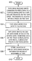
- FIG. 3 illustrates a high level flow chart that depicts modifying data in a tape drive that does not support update-in-place in accordance with the prior art.
- the process starts as depicted by block 300 and thereafter passes to block 302 which illustrates a tape drive receiving a WRITE command to write to a particular record in the tape volume mounted on the tape drive.
- block 304 depicts the tape drive writing the data to the record.
- the process then passes to block 306 which illustrates the tape drive writing an end-of-data mark at the end of the record where the data was stored.
- the end-of-data mark invalidates all data that is stored in the tape volume after the end-of-data mark.
- This end-of-data mark also invalidates any end-of-data mark that may already be stored after the new end-of-data mark. In this manner, only one end-of-data mark can exist at any one time in a prior art tape drive.
- Block 308 depicts storing the location of the end-of-data mark in the media information region which is located at the beginning of the tape.
- the media information region includes information about where each record is physically stored on the tape media. Thus, the media information region can be used to determine in which track a particular record is located. In addition, information about the location of the end-of-data mark is stored in the media information region.
- block 310 illustrates the tape drive completing the write command and returning a response that the write was completed. The process then terminates as illustrated by block 312 .
- FIG. 4 illustrates a high level flow chart that depicts accessing a particular record in a tape drive that does not support update-in-place in accordance with the prior art.
- the process starts as depicted by block 400 and thereafter passes to block 402 which illustrates the tape drive controller receiving a command to access data that is stored in a particular record.
- block 404 depicts a determination of whether the particular record is located before or after the end-of-data mark. This determination is made by using the information stored in the media information region.
- the process passes to block 406 which illustrates accessing the data in the record. The process then terminates as depicted by block 408 .
- the process passes to block 410 which illustrates returning a notice that the requested data is invalid. The process then terminates as depicted by block 408 .
- FIG. 5A is a block diagram of a tape media 500 that includes an end-of-data mark 518 that invalidates only the data in a track that is stored after data that was modified in the track in accordance with the present invention.
- One end-of-data mark is stored in tape media 500 .
- Tape media 500 is typically a tape capable of being mounted on a tape drive.
- Tape 500 has a first end 502 and a second end 504 . These ends may be physical ends or logical ends (as is the case with a tape device that supports mid-point load).
- Tape 500 includes multiple different tracks. Tape 500 includes tracks 506 , 508 , 510 , 512 , 514 , and 516 . Each track may be a single track or a group of tracks. As used herein, the term “track” can mean a single track or a group of multiple tracks that are treated together as if the group were a single entity. Each track, or group of tracks, in the tape serves as if each track or group of tracks were a separate independent tape.
- Data is written to tape 500 in multiple passes of the tape. For example, during the first pass of the tape, data is written to track 506 from first end 502 of tape 500 to second end 504 of tape. During the second pass of the tape, data is written to track 508 from second end 504 of tape 500 to first end 502 of tape. During the third pass of the tape, data is written to track 510 from first end 502 to second end 504 . During the fourth pass of the tape, data is written to track 512 from second end 504 to first end 502 . During the fifth pass of the tape, data is written to track 514 from first end 502 to second end 504 .
- data has been modified in a particular record in section 520 in track 510 .
- end-of-data mark 518 was written at the end of the modified record.
- Data that is located after the end-of-data mark 518 and before second end 504 is invalidated. All other data in other tracks is not invalidated by end-of-data mark 518 .
- data in tracks 506 and 508 remains valid after end-of-data mark 518 is stored.
- Data that is stored in section 520 which is before end-of-data mark 518 in track 510 is valid after end-of-data mark 518 is written.
- Data that is stored after end-of-data mark 518 , in section 522 , in track 510 is invalid after end-of-data mark 518 is written.
- data in tracks 512 , 514 , and 516 remains valid.
- FIG. 5B is a block diagram of a tape media that includes an end-of-data mark in two tracks where each end-of-data mark invalidates only the data in the track that is stored after data that was modified in the track in accordance with the present invention.
- FIG. 5B depicts the tape media 500 of FIG. 5A at a later time after additional data has been modified in a record in track 512 .
- Additional data has been modified that is stored in a second particular record in section 528 in track 512 .
- end-of-data mark 524 was written at the end of the second record. Data that is located after the end-of-data mark 524 that is located in track 512 is invalidated. All other data in other tracks is not invalidated by end-of-data mark 524 .
- data in tracks 506 , 508 , and section 520 of track 510 remains valid after end-of-data mark 524 is stored. Data that is stored in section 528 before end-of-data mark 524 in track 512 is valid after end-of-data mark 524 is written.
- End-of-data mark 524 Data that is stored after end-of-data mark 524 , in section 526 , and before first end 502 in track 512 is invalid after end-of-data mark 524 is written. After end-of-data mark 524 is written, data in tracks 514 and 516 remains valid. In addition, writing end-of-data mark 524 does not affect end-of-data mark 518 .
- the locations of end-of-data mark 518 and end-of-data mark 524 are stored in the media information region at the beginning of the tape.
- FIG. 6 depicts a high level flow chart that illustrates modifying data in a tape drive that supports update-in-place in accordance with the present invention.
- the process starts as depicted by block 600 and thereafter passes to block 602 which illustrates the tape drive receiving a write command to write data to a particular record in a tape volume that is mounted on the tape drive.
- the record is located within a particular track on the tape.
- block 604 depicts the tape drive writing the data to the record.
- the process then passes to block 606 which illustrates the tape drive writing an end-of-data mark at the end of the data that was stored in the particular record in the track.
- the remaining data on that track that is located after the end-of-data mark is invalidated by the end-of-data mark.
- the data that is located on all other tracks on the tape is not invalidated.
- the new end-of-data mark invalidates any existing end-of-data mark in this particular track.
- the new end-of-data mark does not invalidate any existing end-of-data mark in any other track.
- multiple end-of-data marks can simultaneously coexist in the tape media. Only one end-of-data mark can exist at one time within a single track. A new end-of-data mark will only affect another existing end-of-data mark within the same track as the new end-of-data mark.
- Block 608 depicts the tape controller storing the location of this end-of-data mark in the media information region at the beginning of the tape. The process then terminates as illustrated by block 610 .
- FIG. 7 illustrates a high level flow chart that depicts accessing a particular record in a tape drive that supports update-in-place in accordance with the present invention.
- the process starts as depicted by block 700 and thereafter passes to block 702 which illustrates a tape drive controller receiving a command to access data that is stored in a particular record.
- block 704 depicts using the media information region to determine whether there is an end-of-data mark in the track that includes this particular record.
- Block 706 illustrates a determination of whether or not there is an end-of-data mark in this particular track. If a determination is made that there is no end-of-data mark in this particular track, the process passes to block 710 . Referring again to block 706 , if a determination is made that there is an end-of-data mark in this particular track, the process passes to block 708 which depicts a determination of whether or not this particular record is before or after the end-of-data mark already stored in this track. If a determination is made that this particular record is before the end-of-data mark already stored in this track, the process passes to block 710 which illustrates accessing the data in the record.
- FIG. 8 is a block diagram of a data processing system that may include the present invention in accordance with the present invention.
- Data processing system 800 may be a symmetric multiprocessor (SMP) system including a plurality of processors 802 and 804 connected to system bus 806 . Alternatively, a single processor system may be employed.
- SMP symmetric multiprocessor
- memory controller/cache 808 Also connected to system bus 806 is memory controller/cache 808 , which provides an interface to local memory 809 .
- I/O bus bridge 810 is connected to system bus 806 and provides an interface to I/O bus 812 .
- Memory controller/cache 808 and I/O bus bridge 810 may be integrated as depicted.
- Peripheral component interconnect (PCI) bus bridge 814 connected to I/O bus 812 provides an interface to PCI local bus 816 .
- PCI bus 816 A number of modems may be connected to PCI bus 816 .
- Typical PCI bus implementations will support four PCI expansion slots or add-in connectors.
- Communications links to other network computers may be provided through modem 818 and network adapter 820 connected to PCI local bus 816 through add-in boards.
- Additional PCI bus bridges 822 and 824 provide interfaces for additional PCI buses 826 and 828 , from which additional modems or network adapters may be supported. In this manner, data processing system 800 allows connections to multiple network computers.
- a memory-mapped graphics adapter 830 and hard disk 832 may also be connected to I/O bus 812 as depicted, either directly or indirectly.
- FIG. 8 may vary and could indeed be a mainframe architecture rather than the depicted architecture.
- other peripheral devices such as optical disk drives and the like, also may be used in addition to or in place of the hardware depicted.
- the depicted example is not meant to imply architectural limitations with respect to the present invention.
Abstract
Description
Claims (16)
Priority Applications (1)
| Application Number | Priority Date | Filing Date | Title |
|---|---|---|---|
| US11/026,079 US7167326B1 (en) | 2004-12-30 | 2004-12-30 | Tape drive that supports update-in-place |
Applications Claiming Priority (1)
| Application Number | Priority Date | Filing Date | Title |
|---|---|---|---|
| US11/026,079 US7167326B1 (en) | 2004-12-30 | 2004-12-30 | Tape drive that supports update-in-place |
Publications (1)
| Publication Number | Publication Date |
|---|---|
| US7167326B1 true US7167326B1 (en) | 2007-01-23 |
Family
ID=37663662
Family Applications (1)
| Application Number | Title | Priority Date | Filing Date |
|---|---|---|---|
| US11/026,079 Active US7167326B1 (en) | 2004-12-30 | 2004-12-30 | Tape drive that supports update-in-place |
Country Status (1)
| Country | Link |
|---|---|
| US (1) | US7167326B1 (en) |
Citations (9)
| Publication number | Priority date | Publication date | Assignee | Title |
|---|---|---|---|---|
| US4549234A (en) * | 1981-02-04 | 1985-10-22 | Sony Corporation | Method and apparatus for tracking control |
| US5485321A (en) * | 1993-12-29 | 1996-01-16 | Storage Technology Corporation | Format and method for recording optimization |
| US5710676A (en) * | 1996-03-12 | 1998-01-20 | International Business Machines Corporation | Pre-formatting of a storage media having fixed-size partitions |
| US5793552A (en) * | 1995-11-13 | 1998-08-11 | Seagate Technology, Inc. | Method and apparatus for high speed searching in arcuate scan tape drives |
| US5892633A (en) * | 1996-01-26 | 1999-04-06 | Exabyte Corporation | Dynamic control of magnetic tape drive |
| US5923494A (en) * | 1995-03-20 | 1999-07-13 | Hitachi, Ltd. | Magnetic tape device and method of controlling magnetic tape device |
| US6094605A (en) | 1998-07-06 | 2000-07-25 | Storage Technology Corporation | Virtual automated cartridge system |
| US6674599B1 (en) * | 1998-03-13 | 2004-01-06 | Hewlett-Packard Development Company, L.C. | Data storage method, apparatus and medium |
| US6937411B2 (en) * | 2001-08-06 | 2005-08-30 | International Business Machines Corporation | Method, system, program, and storage cartridge for storing data in a storage medium |
-
2004
- 2004-12-30 US US11/026,079 patent/US7167326B1/en active Active
Patent Citations (13)
| Publication number | Priority date | Publication date | Assignee | Title |
|---|---|---|---|---|
| US4549234A (en) * | 1981-02-04 | 1985-10-22 | Sony Corporation | Method and apparatus for tracking control |
| US5485321A (en) * | 1993-12-29 | 1996-01-16 | Storage Technology Corporation | Format and method for recording optimization |
| US5923494A (en) * | 1995-03-20 | 1999-07-13 | Hitachi, Ltd. | Magnetic tape device and method of controlling magnetic tape device |
| US5793552A (en) * | 1995-11-13 | 1998-08-11 | Seagate Technology, Inc. | Method and apparatus for high speed searching in arcuate scan tape drives |
| US5959800A (en) * | 1996-01-26 | 1999-09-28 | Exabyte Corporation | Early warning for boundary position in serpentine recording |
| US5892633A (en) * | 1996-01-26 | 1999-04-06 | Exabyte Corporation | Dynamic control of magnetic tape drive |
| US5995306A (en) * | 1996-01-26 | 1999-11-30 | Exabyte Corporation | Handling defective frames on hard sectored magnetic tape |
| US6031671A (en) * | 1996-01-26 | 2000-02-29 | Exabyte Corporation | Modulation of buried servo on magnetic tape |
| US6226441B1 (en) * | 1996-01-26 | 2001-05-01 | Exabyte Corporation | Multipurpose digital recording method and apparatus and media therefor |
| US5710676A (en) * | 1996-03-12 | 1998-01-20 | International Business Machines Corporation | Pre-formatting of a storage media having fixed-size partitions |
| US6674599B1 (en) * | 1998-03-13 | 2004-01-06 | Hewlett-Packard Development Company, L.C. | Data storage method, apparatus and medium |
| US6094605A (en) | 1998-07-06 | 2000-07-25 | Storage Technology Corporation | Virtual automated cartridge system |
| US6937411B2 (en) * | 2001-08-06 | 2005-08-30 | International Business Machines Corporation | Method, system, program, and storage cartridge for storing data in a storage medium |
Similar Documents
| Publication | Publication Date | Title |
|---|---|---|
| US9858206B2 (en) | Systems and methods for flushing a cache with modified data | |
| US7310715B2 (en) | Method, apparatus, and computer program product for using an array of high performance storage drives included in a storage array to reduce accessing of an array of lower performance storage drives included in the storage array | |
| US7165144B2 (en) | Managing input/output (I/O) requests in a cache memory system | |
| US5586297A (en) | Partial cache line write transactions in a computing system with a write back cache | |
| US7581063B2 (en) | Method, system, and program for improved throughput in remote mirroring systems | |
| US7644231B2 (en) | Selective information caching on disk drive | |
| US8291175B2 (en) | Processor-bus attached flash main-memory module | |
| US6877065B2 (en) | Advanced read cache management | |
| KR100372293B1 (en) | Cacheable Properties for Virtual Addresses in Virtual and Physical Index Caches | |
| US7546418B2 (en) | System and method for managing power consumption and data integrity in a computer system | |
| US20040049636A1 (en) | Technique for data transfer | |
| US20060174067A1 (en) | Method of caching data | |
| JPS5873085A (en) | Control of memory hierarchy | |
| US10468061B1 (en) | Indexing zones for storage devices | |
| US5694570A (en) | Method and system of buffering data written to direct access storage devices in data processing systems | |
| US8347034B1 (en) | Transparent level 2 cache that uses independent tag and valid random access memory arrays for cache access | |
| US5996049A (en) | Cache-coherency protocol with recently read state for data and instructions | |
| US7254672B1 (en) | Translation device driver for translating between disk device driver and tape device driver commands | |
| US6715030B1 (en) | Apparatus and method for storing track layout information for performing quick write operations | |
| US7949833B1 (en) | Transparent level 2 cache controller | |
| US6330641B1 (en) | Method and apparatus for controlling magnetic disk device | |
| US5617380A (en) | Apparatus and method for drive management for multi-pass storage devices | |
| US7167326B1 (en) | Tape drive that supports update-in-place | |
| US6658536B1 (en) | Cache-coherency protocol with recently read state for extending cache horizontally | |
| US10649902B2 (en) | Reducing translation latency within a memory management unit using external caching structures |
Legal Events
| Date | Code | Title | Description |
|---|---|---|---|
| AS | Assignment |
Owner name: STORAGE TECHNOLOGY CORPORATION, COLORADO Free format text: ASSIGNMENT OF ASSIGNORS INTEREST;ASSIGNORS:BLENDERMANN, STEPHEN H.;MURRAY, THOMAS J.;REEL/FRAME:016147/0185 Effective date: 20041224 |
|
| STCF | Information on status: patent grant |
Free format text: PATENTED CASE |
|
| FPAY | Fee payment |
Year of fee payment: 4 |
|
| FPAY | Fee payment |
Year of fee payment: 8 |
|
| AS | Assignment |
Owner name: SUN MICROSYSTEMS, INC., CALIFORNIA Free format text: MERGER;ASSIGNOR:STORAGE TECHNOLOGY CORPORATION;REEL/FRAME:037692/0820 Effective date: 20061222 Owner name: ORACLE AMERICA, INC., CALIFORNIA Free format text: MERGER AND CHANGE OF NAME;ASSIGNORS:SUN MICROSYSTEMS, INC.;ORACLE USA, INC.;ORACLE AMERICA, INC.;REEL/FRAME:037694/0966 Effective date: 20100212 |
|
| MAFP | Maintenance fee payment |
Free format text: PAYMENT OF MAINTENANCE FEE, 12TH YEAR, LARGE ENTITY (ORIGINAL EVENT CODE: M1553) Year of fee payment: 12 |