US7177346B1 - Radio reception system that can remove interference signal component signal component of another user from a reception signal - Google Patents
Radio reception system that can remove interference signal component signal component of another user from a reception signal Download PDFInfo
- Publication number
- US7177346B1 US7177346B1 US09/204,279 US20427998A US7177346B1 US 7177346 B1 US7177346 B1 US 7177346B1 US 20427998 A US20427998 A US 20427998A US 7177346 B1 US7177346 B1 US 7177346B1
- Authority
- US
- United States
- Prior art keywords
- signal
- users
- signals
- user
- output
- Prior art date
- Legal status (The legal status is an assumption and is not a legal conclusion. Google has not performed a legal analysis and makes no representation as to the accuracy of the status listed.)
- Expired - Fee Related
Links
- 238000004891 communication Methods 0.000 claims abstract description 52
- 238000001514 detection method Methods 0.000 claims description 75
- 238000012545 processing Methods 0.000 claims description 49
- 238000000605 extraction Methods 0.000 claims description 39
- 238000009792 diffusion process Methods 0.000 claims description 20
- 230000005540 biological transmission Effects 0.000 claims description 9
- 230000003044 adaptive effect Effects 0.000 abstract description 99
- 238000010295 mobile communication Methods 0.000 abstract description 3
- 238000006243 chemical reaction Methods 0.000 abstract description 2
- 229920002939 poly(N,N-dimethylacrylamides) Polymers 0.000 abstract 1
- 239000013598 vector Substances 0.000 description 96
- 238000010586 diagram Methods 0.000 description 45
- 238000003491 array Methods 0.000 description 39
- 238000000034 method Methods 0.000 description 16
- 238000012549 training Methods 0.000 description 8
- 238000007476 Maximum Likelihood Methods 0.000 description 6
- 239000000284 extract Substances 0.000 description 6
- 238000004364 calculation method Methods 0.000 description 3
- 238000012986 modification Methods 0.000 description 3
- 230000004048 modification Effects 0.000 description 3
- 239000008186 active pharmaceutical agent Substances 0.000 description 1
- 230000002349 favourable effect Effects 0.000 description 1
- 239000000203 mixture Substances 0.000 description 1
- 230000010355 oscillation Effects 0.000 description 1
Images


Classifications
-
- H—ELECTRICITY
- H04—ELECTRIC COMMUNICATION TECHNIQUE
- H04B—TRANSMISSION
- H04B7/00—Radio transmission systems, i.e. using radiation field
- H04B7/02—Diversity systems; Multi-antenna system, i.e. transmission or reception using multiple antennas
- H04B7/04—Diversity systems; Multi-antenna system, i.e. transmission or reception using multiple antennas using two or more spaced independent antennas
- H04B7/08—Diversity systems; Multi-antenna system, i.e. transmission or reception using multiple antennas using two or more spaced independent antennas at the receiving station
- H04B7/0837—Diversity systems; Multi-antenna system, i.e. transmission or reception using multiple antennas using two or more spaced independent antennas at the receiving station using pre-detection combining
- H04B7/0842—Weighted combining
- H04B7/0848—Joint weighting
- H04B7/0851—Joint weighting using training sequences or error signal
-
- H—ELECTRICITY
- H04—ELECTRIC COMMUNICATION TECHNIQUE
- H04B—TRANSMISSION
- H04B1/00—Details of transmission systems, not covered by a single one of groups H04B3/00 - H04B13/00; Details of transmission systems not characterised by the medium used for transmission
- H04B1/69—Spread spectrum techniques
- H04B1/707—Spread spectrum techniques using direct sequence modulation
- H04B1/7097—Interference-related aspects
- H04B1/7103—Interference-related aspects the interference being multiple access interference
- H04B1/7107—Subtractive interference cancellation
- H04B1/71075—Parallel interference cancellation
-
- H—ELECTRICITY
- H04—ELECTRIC COMMUNICATION TECHNIQUE
- H04B—TRANSMISSION
- H04B1/00—Details of transmission systems, not covered by a single one of groups H04B3/00 - H04B13/00; Details of transmission systems not characterised by the medium used for transmission
- H04B1/69—Spread spectrum techniques
- H04B1/707—Spread spectrum techniques using direct sequence modulation
- H04B1/7097—Interference-related aspects
- H04B1/7103—Interference-related aspects the interference being multiple access interference
- H04B1/7107—Subtractive interference cancellation
- H04B1/71072—Successive interference cancellation
Definitions
- the present invention relates to radio reception systems. More particularly, the present invention relates to a radio reception system by a communication system such as the PDMA (Path Division Multiple Access) and the CDMA (Code Division Multiple Access) that can remove the interference signal component of another user from a reception signal.
- a communication system such as the PDMA (Path Division Multiple Access) and the CDMA (Code Division Multiple Access) that can remove the interference signal component of another user from a reception signal.
- FIGS. 27A–27C show the channel arrangement in various communication systems of FDMA (Frequency Division Multiple Access), TDMA (Time Division Multiple Access), and PDMA.
- FDMA Frequency Division Multiple Access
- TDMA Time Division Multiple Access
- PDMA Packet Data Multiple Access
- the systems of FDMA, TDMA, and PDMA will be described briefly with reference to FIGS. 27A–27C .
- the analog signals of users 1 – 4 are frequency-divided to be transmitted in radio waves of different frequencies f 1 –f 4 .
- the signals of respective users 1 – 4 are separated by frequency filters.
- the digitized signals of respective users are time-divided and transmitted in radio waves of different frequencies f 1 –f 4 at every constant period of time (time slot).
- the signals of respective users are separated by frequency filters and by time synchronization between a base station and each user's mobile terminal device.
- the PDMA system has been proposed to improve the radio wave frequency usability to comply with the spread of portable telephones.
- one time slot of the same frequency is divided spatially to transmit data of a plurality of users.
- the signals of respective users in the PDMA system are separated by means of frequency filters, time synchronization between a base station and each user's mobile terminal device, and a signal extraction device such as an adaptive array.
- FIG. 28 shows a conventional reception system of a base station for use in PDMA.
- Four antennas 3 – 6 are provided to distinguish between user 1 and user 2 .
- the outputs of respective antennas are applied to a frequency conversion circuit 7 to be frequency-converted by a corresponding local oscillation signal Lo respectively and then converted into digital signals by an A/D converter 8 .
- the signals are provided to a DSP (Digital Signal Processor) 10 .
- DSP Digital Signal Processor
- DSP 10 includes adaptive arrays 11 and 12 , a reception signal vector calculator 13 , a memory 14 , a correlation value calculator 15 , and a channel allocation apparatus 16 .
- Each of adaptive arrays 11 and 12 extracts only a particular user signal from the reception signals output from A/D converter 8 .
- Each adaptive array extracts the user signal specified by channel allocation apparatus 16 that will be described afterwards, depending on the weight vector calculation method such as the method using the preamble included in the time slot or the method taking advantage of the feature of the envelope line of a modulation signal being constant.
- Reception signal vector calculator 13 receives the reception signals from A/D converter 8 and the output signals of adaptive arrays 11 and 12 to calculate reception signal vectors corresponding to all the users.
- the calculated reception signal vectors are stored in memory 14 .
- Channel allocation apparatus 16 specifies two users with respect to memory 14 and correlation value calculator 15 .
- Correlation value calculator 15 calculates the cross correlation value of the reception signal vectors of the two specified users out of the reception signal vectors stored in memory 14 .
- Channel allocation apparatus 16 receives the calculated cross correlation value of the reception signal vectors of the two users. When the cross correlation value is equal to or smaller than a constant value, those two users are connected in path multiplex at the same time slot.
- Adaptive arrays 11 and 12 shown in FIG. 28 extract the signals of corresponding users 1 and 2 , respectively.
- a user 3 for example, in addition to users 1 and 2 , transmits a signal from a direction identical to that of user 1 , a signal which is a mixture of the signals of users 1 and 3 will be output from adaptive array 11 .
- the conventional adaptive array 11 cannot separate the signals of users 1 and 3 . Therefore, it was not possible to extract only the signal of user 1 .
- an object of the present invention is to provide a radio reception system that can improve communication quality by canceling the interference component of an unrequired user signal using an interference canceller.
- Another object of the present invention is to provide a radio reception system aimed to further remove the interference component by providing a plurality of stages of user detection devices having the interference removal ability.
- a further object of the present invention is to provide a radio reception system aimed to improve communication quality in a communication system of the CDMA communication method having a large transmission capacity.
- a radio reception system that can receive signals from a plurality of users using a plurality of antennas includes a signal processing circuit applying a predetermined signal process on the signals received on the plurality of antennas, and a user detection device.
- the user detection device includes an adaptive array extracting a signal component corresponding to a particular user out of the plurality of users according to the signals output from the signal processing circuit, a parameter estimator estimating parameter information associated with a relationship of the signal component extracted by the adaptive array with respect to the signal output from the signal processing circuit, and an arithmetic unit providing a signal having the signal component corresponding to a particular user removed from the signal output from the signal processing circuit taking account of the parameter information.
- a radio reception system that can receive signals from a plurality of users using a plurality of antennas includes a signal processing circuit applying a predetermined signal process on the signals received on the plurality of antennas, and a plurality of stages of user detection devices.
- Each stage of the user detection device includes an adaptive array extracting a signal component corresponding to a particular user common to every stage out of the plurality of users according to an input signal, a parameter estimator estimating parameter information associated with relationship of the signal component extracted by the adaptive array with respect to the signal output from the signal processing circuit, and an arithmetic unit providing a signal having the signal component corresponding to the particular user removed from the signal output from the signal processing circuit taking into account the parameter information.
- the plurality of stages of user detection devices are connected so that the signal output from the signal processing circuit is applied to the input of the adaptive array of the first stage of the user detection device, and the output of the arithmetic unit of the former stage of two adjacent user detection devices is applied to the input of the adaptive array of the latter stage.
- Each stage of the user detection device includes an adaptive array extracting a signal component corresponding to a particular user out of the plurality of users according to an input signal, a parameter estimator for estimating parameter information associated with relationship of the signal component extracted by the adaptive array with respect to the signal input to the adaptive array, and an arithmetic unit providing a signal having the signal component corresponding to the particular user removed from the signal input to the adaptive array taking into account the parameter information.
- the plurality of stages of user detection devices are connected so that the signal output from the signal processing circuit is applied to the input of the adaptive array of the first stage of the user detection device, and the output of the arithmetic unit of the former stage of two adjacent user detection devices is applied to the input of the adaptive array of the latter stage.
- Each stage of the user detection device includes an adaptive array extracting and providing a signal component corresponding to a particular user differing for each stage out of the plurality of users according to an input signal, a parameter estimator estimating parameter information associated with relationship of the signal component extracted by the adaptive array with respect to the signal input to the adaptive array, and an arithmetic unit removing the signal component corresponding to the particular user from the signal input to the adaptive array taking into account the parameter information.
- the plurality of stages of user detection devices are connected so that the signal output from the signal processing circuit is applied to the input of the adaptive array of the first stage of the user detection device, and the output of the arithmetic unit of the former stage of two adjacent user detection devices is applied to the input of the adaptive array of the latter stage.
- the signals from the plurality of users are signals transmitted by the PDMA communication system.
- the signals from the plurality of users are signals transmitted by the CDMA communication system.
- the signal transmitted by the CDMA communication system is diffused in advance by a predetermined diffusion code at the transmitter side.
- the radio reception system further includes an inverse diffuser that inversely diffuses the signal output from the signal processing circuit by a corresponding diffusion code by the CDMA communication system and applying the inverse-diffused signal to the adaptive array.
- the main advantage of the present invention is that, when a signal of a particular user is to be extracted from signals received from a plurality of users using a plurality of antennas, the interference component by an unrequired user signal component can be removed to improve communication quality.
- Another advantage of the present invention is that, by providing a plurality of stages of user detection devices each having the ability to remove the interference component caused by an unrequired user signal component, the interference component can be removed in a plurality of stages to further improve communication quality.
- a further advantage of the present invention is that the communication quality is improved together with the transmission capacity by removing the interference component caused by an unrequired user signal component from a desired user signal in a communication system of a large transmission capacity such as the CDMA communication system.
- FIG. 1 is a block diagram of a reception signal of a base station for the PDMA according to a first embodiment of the present invention.
- FIG. 2 is a block diagram showing a structure of the arithmetic unit of FIG. 1 .
- FIGS. 3 and 4 are block diagrams of a reception system of a base station for the PDMA according to a second embodiment and a third embodiment, respective, of the present invention.
- FIG. 5 is a block diagram showing a structure of the arithmetic unit of FIG. 4 .
- FIGS. 6 , 7 , and 8 are block diagrams of a reception system of a base station for the PDMA according to a fourth embodiment, a fifth embodiment, and a sixth embodiment, respectively, of the present invention.
- FIG. 9 is a diagram for describing an operation of the parameter estimator employed in the present invention.
- FIG. 10 is a block diagram of a reception system of a base station for the PDMA according to a seventh embodiment of the present invention.
- FIG. 11 is a block diagram showing a structure of an interference canceller of FIG. 10 .
- FIG. 12 is a block diagram of a reception system of a base station for the PDMA according to an eighth embodiment of the present invention.
- FIG. 13 is a schematic block diagram of the interference canceller of FIG. 12 .
- FIG. 14 is a block diagram showing another example of the interference canceller of FIG. 12 .
- FIGS. 15 and 16 are block diagrams of a reception system of a base station for the PDMA according to a ninth embodiment and a tenth embodiment, respectively, of the present invention.
- FIG. 17 is a block diagram showing the process of the first loop in an example of an adaptive array.
- FIG. 18 is a block diagram showing the process of the second and subsequent loops in an example of an adaptive array.
- FIG. 19 is a block diagram for describing an operation of the adaptive array shown in FIGS. 17 and 18 .
- FIG. 20 is a block diagram of a reception system of a base station for the CDMA according to an eleventh embodiment of the present invention.
- FIG. 21 is a block diagram showing a structure of the arithmetic unit of FIG. 20 .
- FIGS. 22 , 23 , 24 , 25 , and 26 are block diagrams of a reception system of a base station for the CDMA according to a twelfth embodiment, a thirteenth embodiment, a fourteenth embodiment, a fifthteenth embodiment, and a sixteenth embodiment, respectively, of the present invention.
- FIGS. 27A , 27 B and 27 C are channel arrangement diagrams of a user signal according to communication systems of the FDMA, TDMA, and PDMA, respectively.
- FIG. 28 is a block diagram showing a conventional reception system of a base station for the PDMA.
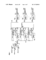
- FIG. 1 is a block diagram showing a reception system of a base station for the PDMA according to a first embodiment of the present invention.
- the reception system of the first embodiment separates signals S 1 (t), . . . , S k (t), . . . , S m (t) from m (m is an integer of at least 2) users 1 , . . . , k, . . . , m transmitted at the same time to extract the signals in parallel.
- the reception system of the PDMA base station includes four antennas 3 – 6 , a frequency converter circuit 7 , and an A/D converter 8 , similar to the conventional system of FIG. 28 .
- the input signal vector X 1 (t) output from A/D converter 8 is applied to an arithmetic unit 100 , the first stage of adaptive arrays AA 11 , . . . , AA k1 , . . . , AA m1 , and parameter estimators PE 11 , . . . , PE k1 , . . . , PE m1 .
- the details of the adaptive array will be described afterwards.
- User signals Y 11 (t), . . . , Y k1 (t), . . . , Y m1 (t), each of which includes most intensively the signal component of a corresponding user (also including the interference signal component from other users) are extracted from adaptive arrays AA 11 , . . . , AA k1 , . . . , AA m1 to be applied to arithmetic array 100 and also to detectors DE 11 , . . . , DE k1 , . . . , DE m1 , respectively, to be detected.
- Parameter estimators PE 11 , . . . , PE k1 , . . . , PE m1 estimate reception signal coefficient vectors H 11 , . . . , H k1 , . . . , H m1 of a corresponding users respectively according to the input signal vector X 1 (t) and the corresponding detected outputs of detectors DE 11 , . . . , DE k1 , . . . , DE m1 .
- the estimated vectors are applied to arithmetic unit 100 . More specifically, each parameter estimator estimates how much the corresponding user signal component is included in the input signal vector and how much the phase of the corresponding user signal component is rotated with respect to the input signal vector.
- the further input signal vector X i2 (t) of the relevant user i is calculated and output. The operation of arithmetic unit 100 will be described in detail afterwards with reference to FIG. 2 .
- Arithmetic unit 100 provides input signal vectors X 12 (t), . . . , X k2 (t), . . . , X m2 (t) corresponding to respective users to the corresponding second stage of adaptive arrays AA 12 , . . . , AA k2 , . . . , AA m2 .
- User signals Y 12 (t), . . . , Y k2 (t), . . . , Y m2 (t) output from adaptive arrays AA 12 , . . . , AA k2 , . . . , AA m2 are detected by corresponding detectors DE 12 , . . . , DE k2 , . . . , DE m2 , respectively, to be output as further user signals S 1 (t), . . . , S k (t), . . . , S m (t).
- FIG. 2 is a specific block diagram of arithmetic unit 100 of FIG. 1 .
- arithmetic unit 100 is formed of multipliers MP 1 , . . . , MP k ⁇ 1 , MO k+1 , . . . , MP m and an adder AD k .
- a multiplier MP k and adders AD 1 , . . . , AD k ⁇ 1 , AD k+1 , . . . , AD m are also incorporated in arithmetic unit 100 in addition to the multipliers and adders shown in the drawings.
- Multipliers MP 1 , . . . , MP k ⁇ 1 , MP k+1 , . . . , MP m are applied with user signals Y 11 (t), . . . , Y (k ⁇ 1)1 (t), Y (k+1)1 (t), . . . , Y m1 (t) from adaptive arrays AA 11 , . . . , AA k ⁇ 1 , AA k+1 , . . . , AA m and reception signal coefficient vectors H 11 , . . . , H (k ⁇ 1)1 , H (k+1)1 , . . . , H m1 from parameter estimators PE 11 , . . . , PE (k ⁇ 1)1 , PE (k+1)1 , . . . , PE m1 , respectively.
- the new input vector signal X k2 (t) having the interference signal component removed considerably by arithmetic unit 100 is applied to the corresponding adaptive array AA k2 ( FIG. 1 ) of the second stage.
- the ratio of the interference signal component of other users included in the final output user signal S k (t) can be reduced sufficiently to allow realization of favorable communication property.
- each of the adders not shown other than adder AD k receives the outputs from corresponding ones of multipliers MP 1 , . . . , MP k . . . , MP m excluding the multiplier corresponding to the relevant adder, and input signal vector X 1 (t).
- Each adder provides the new input signal vector shown in FIG. 1 , which is applied to the corresponding adaptive array of the second stage.
- X 1 (t) [ x 1 ( t ), x 2 ( t ), . . . , x n ( t )] T (1)
- adaptive arrays AA 11 , . . . , AA k1 , . . . , AA m1 of the first stage operate relatively favorably, then Y i1 (t) ⁇ S i (t).
- input signal vector X k2 (t) used in the signal detection of user k of the second stage can be obtained by the following equation (6).
- X k2 ( t ) X 1 ( t ) ⁇ H 1 S 1 ( t ) ⁇ . . . ⁇ H k ⁇ 1 S k ⁇ 1 ( t ) ⁇ H k+1 S k+1 ( t ) ⁇ . . . ⁇ H m S m ( t ) (6)
- detectors DE 11 , . . . , DE k1 , . . . , DE m1 can be arranged in adaptive arrays AA 11 , . . . , AA k1 , . . . , AA m1 , so that user signals Y 11 (t), . . . , Y k1 (t), . . . , Y m1 (t) are applied to corresponding detectors, respectively.
- each detector can be incorporated in arithmetic unit 100 . Further alternatively, the detector can be omitted, although the characteristic will be degraded slightly.
- FIG. 3 is a block diagram showing the second embodiment of the present invention.
- the embodiment of FIG. 3 further improves the property by providing in series a plurality of stages of user detection device, as well as detectors, each stage being formed of the adaptive arrays, the parameter estimators, and the arithmetic unit of FIG. 1 to reduce in a step-manner the ratio of the signal component of other users included in the user signal output from each stage.
- the operation of the circuit of each stage has been already described in detail with reference to FIGS. 1 and 2 , and will not be repeated here.
- FIG. 4 is a block diagram showing the third embodiment of the present invention.
- input signal vector X 1 (t) output from A/D converter 8 is applied to adaptive arrays AA 11 , . . . , AA k1 , . . . , AA m1 and to arithmetic unit 201 .
- Adaptive arrays AA 11 , . . . , AA k1 , . . . , AA m1 extract and provide to arithmetic unit 201 corresponding user signals Y 11 (t), . . . , Y k1 (t), . . . , Y m1 (t), respectively.
- FIG. 5 is a specific block diagram of arithmetic unit 201 of FIG. 4 .
- FIG. 5 only the portion that carries out a signal process corresponding to user k is depicted out of the entire structure of arithmetic unit 201 for the sake of simplifying the description.
- the circuit of the same structure is provided corresponding to each of users 1 , . . . , k ⁇ 1, k+1, . . . , m besides user k.
- Arithmetic unit 201 includes parameter estimators PE 1k1 , . . . , PE (k ⁇ 1)k1 , PE (k+1)k1 , . . . , PE mk1 and multipliers MP 1k1 , . . . , MP (k ⁇ 1)k1 , MP (k+1)k1 , . . . , MP mk1 as the circuitry corresponding to user k.
- Parameter estimators PE 1k1 , . . . , PE (k ⁇ 1)k1 , PE (k+1)k1 , . . . , PE mk1 estimate reception signal coefficient vectors H 1k1 , . . . , H (k ⁇ 1)k1 , H (k+1)k1 , . . . , H mk1 of corresponding users according to input signal vector X k1 (t) and corresponding user signals Y 11 (t), . . . , Y (k ⁇ 1)1 (t), Y (k+1)1 (t), . . . , Y m1 (t), respectively.
- Multipliers MP 1k1 , . . . , MP (k ⁇ 1)k1 , MP (k+1)k1 , . . . , MP mk1 receive user signals Y 11 (t), . . . , Y (k ⁇ 1)1 (t), Y (k+1)1 (t), . . . , Y m1 (t) from adaptive arrays AA 11 , . . . , AA (k ⁇ 1)1 , AA (k+1)1 , . . . , AA m1 , and reception signal coefficient vectors H 1k1 , . . . , H (k ⁇ 1)k1 , H (k+1)k1 , . . . , H mk1 from parameter estimators PE 1k1 , . . . , PE (k ⁇ 1)k1 , PE (k+1)k1 , . . . , PE mk1 .
- multipliers MP 1k1 , MP (k ⁇ 1)k1 , MP (k+1)k1 , . . . , MP mk1 are applied to the negative inputs of adder AD k1 .
- Input signal vector X k1 (t) is applied to the positive inputs of adder AD k1 . Accordingly, the signal components corresponding to users other than user k are subtracted from input signal vector X k1 (t), whereby the signal component X k2 (t) corresponding to user k is output from adder AD k1 . As a result, the interference signal component will be removed considerably.
- the user detection device of each stage is constituted by the adaptive arrays, the parameter estimators, and the remaining portion of the arithmetic unit.
- input signal vector X k1 (t) of the k-th adaptive array AA k1 and arithmetic unit 201 out of the circuitry forming the user detection device of the first stage is represented by the following equation (8).
- X k1 ( t ) [ x 1k1 ( t ), x 2k1 ( t ), . . . , x nk1 ( t )] T
- x jk1 ( t ) h j1k1 S 1 ( t )+ h j2k1 S 2 ( t )+ . . .
- N k1 ( t ) [ n 1k1 ( t ), n 2k1 , ( t ), . . . , n nk1 , ( t )] T (12)
- H ik1 refers to the reception signal coefficient vector of the signal transmitted from user i included in the input signal vector of the circuit that extracts the signal transmitted from user k, out of the first stage of the user detection devices connected in series.
- N k1 (t) refers to the noise vector included in the input signal vector of the circuit that extracts the signal transmitted from user k, out of the first stage of the user detection devices connected in series.
- output signal X k2 (t) of arithmetic unit 201 is represented by the following equation (13).
- X k2 ( t ) X k1 ( t ) ⁇ H 1k1 Y 11 ( t ) ⁇ . . .
- FIG. 6 is a block diagram showing the reception system of a base station for the PDMA according to the fourth embodiment of the present invention.
- the fourth embodiment is directed to extract a more accurate user signal S k+1 (t) in the user detection device of the next stage by using a signal vector obtained by multiplying the detected signal S k (t) of user k by the reception signal coefficient vector H k output from the parameter estimator and subtracting this multiplied value from the reception signal vector X k (t) used in the signal detection of user k in the user detection device of the k-th stage, as the input signal vector X k+1 (t) of the adaptive array of the user detection device of the (k+1)th stage.
- input signal vector X 1 (t) output from A/D converter 8 is applied to adaptive array AA 11 , and also to adder AD 1 and parameter estimator PE 11 .
- User signal Y 1 (t) is extracted from input signal vector X 1 (t) by adaptive array AA 11 and detected by detector DE 11 to be output as user signal S 1 (t).
- User signal S 1 (t) is applied to parameter estimator PE 11 and multiplier MP 1 .
- Parameter estimator PE 11 estimates reception signal coefficient vector H 1 according to detected user signal S 1 (t) and input signal vector X 1 (t). Multiplier MP 1 multiplies reception signal coefficient vector H 1 by user signal S 1 (t) and provides the result to adder AD 1 . The H 1 S 1 (t) component is subtracted from input signal vector X 1 (t) by adder AD 1 . The obtained signal vector is set as the input signal vector X 2 (t) of the user detection device of the next stage.
- the user detection device of each stage is formed as the user detection device of the first stage.
- the user detection device of the k-th stage includes an adaptive array AA k1 , a detector DE k1 , a parameter estimator PE k1 , a multiplier MP k , and an adder AD k .
- User signal S m (t) of user m is output via adaptive array AA m1 and detector DE m1 from adder AD m ⁇ 1 of the user detection device of the last stage (m ⁇ 1 th) stage.
- Equations (1)–(5) described in the first embodiment of FIGS. 1 and 2 are also applied to the present fourth embodiment.
- the output of detector DE k1 of the user detection device of the k-th stage is S k (t).
- Parameter estimator PE k1 outputs a reception signal coefficient vector H k of the signal of user k according to the detected user signal S k (t) of user k and input signal vector X k (t).
- Multiplier MP k multiplies user signal S k (t) by reception signal coefficient vector H k .
- the result is subtracted from input signal vector X k (t) by adder AD k .
- the result is set as input signal vector X k+1 (t) to the user detection device of the next stage.
- X k+1 ( t ) X k ( t ) ⁇ H k S k ( t ) (19)
- input vector signal X k+1 (t) is a vector signal having the component of user signal S k (t) (i. e., the interference signal component for adaptive array AA (k+1)1 of the user detection device of the (k+1)th stage) from input signal vector X k (t) of the user detection device of the preceding stage. Therefore, the relevant adaptive array operates more favorably by using X k+1 (t) than X k (t) as the input signal vector for adaptive array AA (k+1)1 of the user detection device of the (k+1)th stage. As a result, a more proper signal S k+1 (t) of user (k+1) can be extracted.
- FIG. 7 is a diagram showing the fifth embodiment of the present invention which is a modification of the fourth embodiment shown in FIG. 6 .
- the modification shown in FIG. 7 has a structure in which user signals Y 1 , (t) . . . , Y k (t), . . . , Y m ⁇ 1 (t) output from adaptive arrays AA 11 , .
- AA k1 , . . . , AA (m ⁇ 1)1 are applied to parameter estimators PE 11 , . . . , PE k1 , . . . , PE (m ⁇ 1)1 and multipliers MP 1 , . . . , MP k , . . . , MP m ⁇ 1 .
- Parameter estimators PE 11 , . . . , PE k1 , . . . , PE m ⁇ 1 output reception signal coefficient vectors H 1 , . . . , H k , . . . H m ⁇ 1 of the first stage, . . . , the (k)th stage, . . . , the (m ⁇ 1)th stage from user signals Y 1 (t), . . . , Y k (t), . . . , Y m ⁇ 1 (t) and input signal vectors X 1 (t), . . . , X k (t), . . . , X m ⁇ 1 (t).
- Multipliers MP 1 , . . . , MP k , . . . , MP m ⁇ 1 multiply reception signal coefficient vectors H 1 , . . . , H k , . . . , H m ⁇ 1 by user signals Y 1 (t), . . . , Y k (t), . . . , Y m ⁇ 1 (t).
- Adders AD 1 , . . . , AD k , . . . , AD m ⁇ 1 subtract H 1 Y 1 (t), . . . , H k Y k (t), . . .
- H m ⁇ 1 Y m ⁇ 1 (t) which are the multiplied result from input signal vectors X 1 (t), . . . , X k (t), . . . , X m ⁇ 1 (t).
- the remaining operation is identical to the operation of the previous embodiment of FIG. 6 .
- FIG. 8 shows the sixth embodiment of the present invention which is a modification of the fourth embodiment of FIG. 6 .
- user signals Y 1 (t), . . . , Y k (t), . . . , Y m ⁇ 1 (t) output from adaptive arrays AA 11 , . . . , AA k1 , . . . , AA (m ⁇ 1)1 are applied to multipliers MP 1 , . . . , MP k , . . . , MP m ⁇ 1 instead of user signals S 1 (t) . . . , S k (t) . . . , S m ⁇ 1 (t) of FIG. 6 .
- the remaining structure is similar to that of the sixth embodiment of FIG. 6 .
- a signal S k+1 (t) of a more correct level of user k+1 can be extracted by using the signal vector obtained by multiplying the detected signal Y k (t) of user k by reception signal coefficient vector H k output from the parameter estimator and subtracting the multiplied value from input signal vector X k (t) used in the user detection device of the k-th stage, as input signal vector X k+1 (t) of adaptive array AA (k+1)a of the user detection device of the (k+1)th stage.
- FIG. 9 is a diagram to describe the operation of the parameter estimator used in each of the above embodiments.
- input signal vector X k (t) of the k-th parameter estimator PE k1 connected in parallel is represented by the following equation (21).
- X k ( t ) [ x 1k ( t ), x 2k ( t ), . . . , x nk ( t )] T
- the ensemble average between input signal vector X k (t) corresponding to user k and user signal S k (t) is calculated.
- the output signal Y k (t) of the k-th adaptive array AA k1 can be used instead of user signal S k (t) of user k since Y k (t) ⁇ S k (t) is established.
- reception signal coefficient vector H k of signal S k (t) of user k is calculated.
- reception signal coefficient vector H k of the user signal of user k can be obtained by calculating the ensemble average between input signal vector X k (t) of user k and the detected signal S k (t) of user k by the parameter estimator PE k1 .
- FIG. 10 is a block diagram showing the reception system of a base station for the PDMA according to the seventh embodiment of the present invention.
- interference cancellers 20 and 21 are connected to the outputs of the conventional adaptive arrays 11 and 12 , respectively, shown in FIG. 28 .
- the user signals output from interference cancellers 20 and 21 are fed back to reception signal vector calculator 13 .
- the remaining structure is identical to the structure of FIG. 28 . Therefore, the description of common components will not be repeated.
- the desired user signal, interference user signal, and noise are included in the signal extracted by each of adaptive arrays 11 and 12 .
- the power of the desired user signal is greatest among these signals.
- Each of interference cancellers 20 and 21 estimates the interference user signal using the preamble which is the known signal component included in the interference user signal to remove the interference user signal component included in the signal extracted by corresponding adaptive arrays 11 and 12 .
- a desired signal component is output from DSP 10 with the interference component further suppressed.
- FIG. 11 is a block diagram showing a structure of the interference canceller of FIG. 10 .
- interference canceller 20 includes adders 201 and 202 , an error calculator 203 , a maximum likelihood estimation equalizer 204 , a parameter estimator 205 , multipliers 206 and 207 , switches 208 and 209 , and a memory 210 .
- Parameter estimator 205 estimates the values of coefficients A and B according to the input signal.
- Error calculator 203 calculates the absolute value of signal Y (t) that is input to error calculator 203 .
- Maximum likelihood estimation equalizer 204 selects the series of signals with the smallest error and outputs that signal. Switches 208 and 209 switch the input signal between the training period and the data period for output. During the training period, the estimation accuracy of the coefficient estimated by parameter estimator 205 is improved using the training signal stored in memory 210 . During the data period, the input is switched to the maximum likelihood estimation equalizer 204 side. The signal series with the smallest error is searched by using the code sequentially specified by maximum likelihood estimation equalizer 204 .
- FIG. 12 is a block diagram showing a structure of a reception system of a base station for the PDMA according to the eighth embodiment of the present invention.
- FIG. 13 is a schematic block diagram of the interference canceller of FIG. 12 .
- interference cancellers 22 and 23 are provided instead of interference cancellers 20 and 21 of the embodiment shown in FIG. 10 .
- the signal extracted by adaptive array 11 is applied to interference canceller 22 as a desired user signal and to interference canceller 23 as an interference user signal.
- the signal extracted by adaptive array 12 is applied to interference canceller 23 as a desired user signal and to interference canceller 23 as an interference user signal.
- Interference canceller 22 includes a detector circuit 221 , a correlation value calculator 222 , an adder 223 , and a multiplier 224 , as shown in FIG. 13 .
- the number of users of path multiplex in interference canceller 22 of FIG. 13 is 2, the signal of input 1 is X 1 (t), the signal of input 2 is X 2 (t), the output signal of detector circuit 221 is X 3 (t), and the output signal is Y (t).
- the signal of user 1 of FIG. 13 is S 1 (t)
- the signal of user 2 is S 2 (t)
- the noise component included in the signal of input 1 is n 1 (t)
- the noise component included in the signal of input 2 is n 2 (t)
- the coefficient of the signal of user 1 included in the signal of input 1 is A
- the coefficient of the signal of user 2 included in the signal of input 1 is B
- the coefficient of the signal of user 1 included in the signal of user 2 is C
- the coefficient of the signal of user 2 included in the signal of input 2 is D
- the two input signals x 1 (t), x 2 (t) are represented by the following equations, respectively.
- output signal Y (t) is represented by the following equation.
- interference user component x 2 (t) is removed from signal x 1 (t) of input 1 .
- FIG. 14 is a block diagram showing another example of the interference canceller of FIG. 12 .
- Interference canceller 22 of FIG. 14 has a configuration in which a detector 211 is provided in the interference canceller of FIG. 11 .
- interference canceller 22 of FIG. 14 provides the detected output of detector 211 as interference user signal S 2 (t) to multiplier 207 via switch 209 .
- the remaining structure and operation are similar to those of the previous embodiment described with reference to FIG. 11 .
- FIG. 15 is a block diagram showing a reception system of a base station for the PDMA according to the ninth embodiment of the present invention.
- adaptive arrays 17 and 18 are provided instead of adaptive arrays 11 and 12 of FIG. 10 .
- Training signals are fed back to adaptive arrays 17 and 18 by interference cancellers 20 and 21 , respectively.
- the remaining structure is identical to that of the embodiment of FIG. 10 .
- the number of times of feeding back training signals from the interference cancellers to the adaptive array i.e. the number of times of operating adaptive arrays 17 and 18 and interference cancellers 20 and 21 , is determined in advance. Alternatively, the required number of times is conducted until a predetermined communication quality is achieved.
- FIG. 16 is a block diagram showing a reception system of a base station for the PDMA according to the tenth embodiment of the present invention.
- the present tenth embodiment has a structure in which interference cancellers 20 and 21 shown in FIG. 15 are substituted with interference cancellers 22 and 23 shown in FIG. 12 .
- interference canceller 22 removes the interference user signal component included in the signal extracted by adaptive array 17 according to the signals extracted from adaptive arrays 17 and 18 , so that the signal component of a desired user 1 can be output with the interference component more suppressed.
- the other interference canceller 23 can output the signal component of a desired user 2 with the interference component more suppressed.
- FIGS. 17 and 18 are block diagrams showing examples of adaptive arrays 17 and 18 in each of the above embodiments. Particularly, FIG. 17 is a block diagram showing the signal processing of the adaptive array in the first loop whereas FIG. 18 is a block diagram showing the signal processing in the adaptive array from the second and subsequent loops.
- input ports 181 – 184 are provided in each adaptive array.
- the input signals from the four antennas 3 – 6 that are A/D converted by A/D converter 8 are applied to respective input ports. These input signals are applied to a weight vector calculator 176 and multipliers 171 – 174 .
- Weight vector calculator 176 provides weight vectors w 1 –w 4 using the input signals from input ports 180 – 184 and the training signal corresponding to the signal of a particular user prestored in memory 177 , or the output of adder 175 ( FIG. 17 ), or the output of interference canceller 22 ( FIG. 18 ).
- Multipliers 171 – 174 multiply the input signals of input ports 181 – 184 by weight vectors w 1 –w 4 , and provide the multiplied result to adder 175 .
- Adder 175 adds respective output signals of multipliers 171 – 174 , and provides the result to weight vector calculator 176 , and also to the output port directly in the example of FIG. 17 , and via interference canceller 22 in the example of FIG. 18 .
- FIG. 19 is a flow chart for describing the operation of the adaptive array shown in FIGS. 17 and 18 .
- adaptive array 17 For example 17
- loop i is set to 1.
- Multipliers 171 – 174 of adaptive array 17 shown in FIG. 17 multiply the signals at the input ports by weight vectors w 1 –w 4 and provide the output to adder 175 .
- Weight vector calculator 176 uses the output signal of adder 175 as the training signal and also provides the output signal to interference canceller 22 .
- Interference canceller 22 cancels the interference user signal from the applied signal.
- loop i determines whether the number of times of loop i has become greater than a standard value M. If loop i is not greater than standard value M, the loop number is incremented by +1. When determination is made that loop number i is not 1, adaptive array 17 calculates weight vectors w 1 –w 4 according to the procedure shown in FIG. 18 . Then, the output signal of interference canceller 22 is used as the training signal. Interference canceller 22 carries out signal processing, which is repeated until the number of loop times i arrives at a certain standard value M.
- the interference user component included in a desired user signal extracted by the adaptive array functioning as a signal extraction means is removed by interference removal means. Therefore, the desired user signal component can be extracted having the interference component more suppressed.
- FIGS. 1–19 are related to a reception system of a base station for the PDMA.
- the CDMA communication system is proposed and already in practice.
- the symbol of the transmitted digital data is multiplied by a predetermined diffusion code at the transmission side for transmission as a signal of a significantly higher frequency.
- data is demodulated by inverse-diffusing the reception signal using the diffusion code.
- the following embodiments have the radio reception system of the present invention applied to the CDMA communication system.
- FIG. 20 is a block diagram showing a reception system of a base station for the CDMA according to the eleventh embodiment of the present invention.
- FIG. 21 is a specific block diagram of the arithmetic unit of FIG. 20 .
- the CDMA reception system of the eleventh embodiment shown in FIGS. 20 and 21 is similar to the PDMA reception system of the first embodiment shown in FIGS. 1 and 2 except for the following points.
- Inverse diffusers IS 1 , . . . , IS k , . . . , IS m for inverse-diffusing the signal transmitted by the CDMA communication method and received on antennas 3 – 6 are provided at the preceding stage of the corresponding adaptive arrays and parameter estimators for respective users.
- the reception signals inverse-diffused for respective users by respective inverse diffusers are applied to the corresponding adaptive arrays and parameter estimators similar to the aforementioned PDMA signal.
- respective user signals are extracted and applied to arithmetic unit 100 .
- Arithmetic unit 100 of FIG. 21 is similar to arithmetic unit 100 of FIG. 2 except that diffusers S 1 , . . . , S k ⁇ 1 , S k+1 , . . . , S m are provided to diffuse respective outputs of multipliers MP 1 , . . . , MP k ⁇ 1 , MP k+1 , . . . , MP m . More specifically, the output of each multiplier is diffused again by a corresponding diffusion code for subtraction from the input signal vector X 1 (t) as diffused by the CDMA communication system.
- the outputs of respective adders i. e. the outputs of arithmetic unit 100 , are inverse-diffused again by corresponding inverse diffusers IS 1 , . . . , IS k , . . . , IS m as shown in FIG. 20 to be applied to corresponding adaptive arrays AA 12 , . . . , A k2 , . . . , AA m2 .
- the remaining operation is similar to that of the first embodiment shown in FIGS. 1 and 2 .
- FIG. 22 is a block diagram showing a reception system of a base station for the CDMA according to the twelfth embodiment of the present invention.
- the embodiment of FIG. 22 further improves the property by providing in series a plurality of stages of the combination of inverse diffusers and a user detection device shown in FIG. 20 to reduce in a stepwise manner the ratio of the signal component of other users included in the user signal output from respective stages.
- the operation of the user detection device of each stage is as described in details with reference to FIGS. 1 , 2 , 20 and 21 .
- FIG. 23 is a block diagram showing a reception system of a base station for the CDMA according to the thirteenth embodiment of the present invention.
- the thirteenth embodiment of FIG. 23 is similar to the third embodiment shown in FIG. 4 except for the following points.
- Inverse diffusers IS 1 , . . . , IS k , . . . , IS m to inverse-diffuse input signal vector X 1 (t) transmitted by the CDMA communication system and received on antennas 3 – 6 are provided for respective users.
- X m1 (t) for respective users that are inverse-diffused by respective inverse diffusers are applied to arithmetic unit 201 and also to corresponding adaptive arrays AA 11 , . . . , AA k1 , . . . , AA m1 .
- the remaining operation is similar to that of the third embodiment shown in FIGS. 4 and 5 . Therefore, description thereof will not be repeated.
- FIG. 24 is a block diagram showing a reception system of a base station for the CDMA according to the fourteenth embodiment of the present invention.
- the fourteenth embodiment shown in FIG. 24 is similar to the fourth embodiment shown in FIG. 6 except for the following points.
- Inverse diffusers IS 1 , . . . , IS k , . . . , IS m to inverse-diffuse the input signal vector transmitted by the CDMA communication system are provided at the preceding stage of the corresponding adaptive arrays and parameter estimators for the user detection devices of respective stages.
- the input signal vector inverse-diffused for each user by a corresponding inverse diffuser is applied to the corresponding adaptive array and parameter estimator similar to the aforementioned PDMA signal, whereby respective user signals are extracted by an operation similar to that of the previous fourth embodiment.
- the output of the multiplier in each user detection device is diffused again by a corresponding one of diffusers S 1 , . . . , S k , . . . , S m to carry out subtraction from the corresponding input signal vector as diffused by the CDMA system.
- the remaining operation is similar to that of the fourth embodiment of FIG. 6 . Therefore, the description thereof will not be repeated.
- FIG. 25 is a block diagram showing a reception system of a base station for the CDMA according to the fifteenth embodiment of the present invention.
- the fifteenth embodiment of FIG. 25 is similar to the seventh embodiment of the present invention shown in FIG. 10 except for the following points.
- Inverse diffusers 24 and 25 to inverse-diffuse the input signal vector transmitted by the CDMA communication method and received on antennas 3 – 6 are provided at the preceding stage to the adaptive arrays for respective users.
- the reception signals that are inverse-diffused for respective users by respective inverse diffusers are applied to corresponding adaptive arrays 11 and 12 as the previous PDMA signal, whereby respective user signals are extracted by an operation similar to that of the seventh embodiment.
- FIG. 26 is a block diagram showing a reception system of a base station for the CDMA according to the sixteenth embodiment of the present invention.
- the sixteenth embodiment of FIG. 26 is similar to the eighth embodiment shown in FIG. 12 except for the following points.
- Inverse diffusers 24 and 25 to inverse-diffuse the signal transmitted by the CDMA communication method and received on antennas 3 – 6 are provided at the preceding stage to corresponding adaptive arrays 11 and 12 for respective users.
- the reception signal inverse-diffused for respective users by respective inverse diffusers are applied to corresponding adaptive arrays 11 and 12 as the previous PDMA signal, whereby respective user signals are extracted by an operation identical to that of the eighth embodiment.
- the signal component of a desired user can be extracted with the interference component more suppressed by removing the interference user signal component included in the signal of a corresponding desired user extracted by the signal extraction means using interference removal means. Therefore, the communication quality in a radio communication system such as a mobile communication system can be improved.
Abstract
Description
X 1(t)=[x 1(t), x 2(t), . . . , x n(t)]T (1)
x j(t)=h j1 S 1(t)+h j2 S 2(t)+ . . . +h ji S i(t)+ . . . +h jm S m(t)+n j(t), (j=1, 2, . . . , n) (2)
X 1(t)=H 1 S 1(t)+H 2 S 2(t)+ . . . +H i S i(t)+ . . . +H m S m(t)+N(t) (3)
H i =[h 1i , h 2i , . . . , h ni]T, (i=1, 2, . . . , m) (4)
N(t)=[n 1(t), n 2(t), . . . , n n(t)]T (5)
X k2(t)=X 1(t)−H 1 S 1(t)− . . . −H k−1 S k−1(t)−H k+1 S k+1(t)− . . . −H m S m(t) (6)
X k2(t)=H k S k(t)+N(t) (7)
X k1(t)=[x 1k1(t), x 2k1(t), . . . , x nk1(t)]T (8)
x jk1(t)=h j1k1 S 1(t)+h j2k1 S 2(t)+ . . . +h jik1 S i(t)+ . . . +h jmk1 S m(t)+n jk1(t) (j=1, 2, . . . , n) (9)
X k1(t)=H 1k1 S 1(t)+H 2k1 S 2(t)+ . . . +H ik1 S i(t)+ . . . +H mk1 S m(t)+N(t) (10)
H ik1 =[h 1ik1 , h 2ik1 , . . . , h nik1,]T, (i=1, 2, . . . , m) (11)
N k1(t)=[n 1k1(t), n 2k1, (t), . . . , n nk1, (t)]T (12)
X k2(t)=X k1(t)−H 1k1 Y 11(t)− . . . −H (k−1)k1 Y (k−1)1(t)−H (k+1)k1 Y (k+1)1(t)− . . . −Hmk1 Y m1(t) (13)
Y i1(t)≈S i(t), (i=1, 2, . . . , m) (14)
X k2(t)=X k1(t)−H 1k1 S 1(t)− . . . −H (k−1)k1 S k−1(t)−H (k+1)k1 S k+1(t)− . . . −H mk1 S m(t) (15)
X k2(t)=H kk1 S k(t)+N k2(t) (16)
Y k(t)=a k S k(t)+a k+1 S k+2(t)+ . . . +a m S m(t)+N k(t) (17)
a k≈1, a i≈0, (i=k+1, k+2, . . . , m), |N k(t)|<<|a k| (18)
X k+1(t)=X k(t)−H k S k(t) (19)
X k+1(t)={H k S k(t)+H k+1 S k+1(t)+ . . . +H m S m(t)+N(t)}−H k S k(t)=H k+1 S k+1(t)+ . . . +H m S m(t)+N(t) (20)
X k(t)=[x 1k(t), x 2k(t), . . . , x nk(t)]T (21)
x jk(t)=h jk S k(t)+h jk+1 S k+1(t)+ . . . +h jm S m(t)+ . . . +n j(t), (k=1, 2, . . . , n) (22)
X 1kt)=H k S k(t)+H k+1 S k+1(t)+ . . . +H m S m(t)+N(t) (23)
H i =[h 1i ,h 2i , . . . , h ni]T, (i=k, k+1, . . . m) (24)
N(t)=[n 1(t), n 2(t), . . . , n n(t)]T (25)
E[X k(t)S k(t)]=[E[x 1k(t)S k(t)], E[x 2k(t)S k(t)], . . . E[x nk(t)S k(t)]]T (26)
E[x jk(t)S k(t)]=h jk E[S k(t)S k(t)]+h jk+1 E[S k+1(t)S k(t)]+ . . . +h jm E[S m(t)S k(t)]+E[n j(t)S k(t)], (j=1, 2, . . . , n) (27)
E[S k(t)S k(t)]=1 (28)
E[S i(t)S k(t)]=0, (i=k+1, k+2, . . . m) (29)
E[n j(t)S k(t)]=0, (j=1, 2, . . . , n) (30)
Therefore,
E[x jk(t)S k(t)]=h jk, (j=1, 2, . . . , n) (31)
E[X k(t)S k(t)]=[h 1k , h 2k , . . . , h nk]T =H k (32)
x(t)=AS 1(t)+BS 2(t)+n(t)
Y(t)=AS 1(t)−A′S 1′(t)+BS 2(t)−B′S 2′(t)+n(t)
x 1(t)=AS 1(t)+BS 2(t)+n 1(t)
x 2(t)=CS 1(t)+DS 2(t)+n 2(t)
A≈1, D≈1
A>>B, C<<D
S 1(t), S 2(t)>>n 1(t), n 2(t)
x 3(t)=S 2(t)
E[x 1(t)x 3(t)]=AE[S 1(t)S 2(t)]+BE[S 2(t)S 2(t)]+E[n 1(t)S 2(t)]
E[S 1(t)S 2(t)]=0
E[S 2(t)S 2(t)]=1
E[n 1(t)S 2(t)]=0
E[x 1(t)x 2(t)]=B
Y(t)=x 1(t)−x 3(t)*E[x 1(t)x 3(t)]=AS 1(t)+BS 2(t)+n 1(t)−BS 2(t)=AS 1(t)+n 1(t)
Claims (28)
Priority Applications (1)
| Application Number | Priority Date | Filing Date | Title |
|---|---|---|---|
| US11/580,868 US7496131B2 (en) | 1997-12-04 | 2006-10-16 | Radio reception system that can remove interference signal component |
Applications Claiming Priority (3)
| Application Number | Priority Date | Filing Date | Title |
|---|---|---|---|
| JP33398097 | 1997-12-04 | ||
| JP6680298 | 1998-03-17 | ||
| JP32529198A JPH11331125A (en) | 1997-12-04 | 1998-11-16 | Radio receiving system |
Related Child Applications (1)
| Application Number | Title | Priority Date | Filing Date |
|---|---|---|---|
| US11/580,868 Continuation US7496131B2 (en) | 1997-12-04 | 2006-10-16 | Radio reception system that can remove interference signal component |
Publications (1)
| Publication Number | Publication Date |
|---|---|
| US7177346B1 true US7177346B1 (en) | 2007-02-13 |
Family
ID=27299249
Family Applications (2)
| Application Number | Title | Priority Date | Filing Date |
|---|---|---|---|
| US09/204,279 Expired - Fee Related US7177346B1 (en) | 1997-12-04 | 1998-12-03 | Radio reception system that can remove interference signal component signal component of another user from a reception signal |
| US11/580,868 Expired - Fee Related US7496131B2 (en) | 1997-12-04 | 2006-10-16 | Radio reception system that can remove interference signal component |
Family Applications After (1)
| Application Number | Title | Priority Date | Filing Date |
|---|---|---|---|
| US11/580,868 Expired - Fee Related US7496131B2 (en) | 1997-12-04 | 2006-10-16 | Radio reception system that can remove interference signal component |
Country Status (2)
| Country | Link |
|---|---|
| US (2) | US7177346B1 (en) |
| JP (1) | JPH11331125A (en) |
Cited By (4)
| Publication number | Priority date | Publication date | Assignee | Title |
|---|---|---|---|---|
| US20040004946A1 (en) * | 2000-09-22 | 2004-01-08 | Hirotaka Koike | Radio base system and transmission timing control method |
| US20040072560A1 (en) * | 2001-01-31 | 2004-04-15 | Koichi Mori | Radio base system, channel allocation method and channel allocating program |
| EP1322128A4 (en) * | 2000-09-04 | 2009-11-18 | Sanyo Electric Co | Radio receiving system and method |
| US20090305713A1 (en) * | 2006-03-27 | 2009-12-10 | Kyocera Corporation | Base Station Device and Channel Allocation Method |
Families Citing this family (7)
| Publication number | Priority date | Publication date | Assignee | Title |
|---|---|---|---|---|
| JP2001196835A (en) * | 2000-01-17 | 2001-07-19 | Matsushita Electric Ind Co Ltd | Incoming direction estimating method and radio receiver |
| JP2001203619A (en) * | 2000-01-19 | 2001-07-27 | Matsushita Electric Ind Co Ltd | Wireless base station device and wireless communication method |
| JP3515033B2 (en) * | 2000-01-19 | 2004-04-05 | 松下電器産業株式会社 | Interference signal removal apparatus and interference signal removal method |
| KR100708930B1 (en) | 2000-08-25 | 2007-04-17 | 에스케이 텔레콤주식회사 | Apparatus and method for cancelling a multi access interference using an adaptive antenna array in multi-carrier code division multiple access system |
| US20040004951A1 (en) | 2002-07-05 | 2004-01-08 | Interdigital Technology Corporation | Method for performing wireless switching |
| KR20090113915A (en) * | 2007-03-06 | 2009-11-02 | 미쓰비시덴키 가부시키가이샤 | Radio communication system |
| CN102739262B (en) * | 2012-06-12 | 2014-09-03 | 成都林海电子有限责任公司 | Satellite communication gateway station signal demodulation processing board based on a CPCI (Compact Peripheral Component Interconnect) interface |
Citations (14)
| Publication number | Priority date | Publication date | Assignee | Title |
|---|---|---|---|---|
| US5387900A (en) * | 1992-11-19 | 1995-02-07 | Sensormatic Electronics Corporation | EAS system with improved processing of antenna signals |
| US5579304A (en) * | 1994-03-10 | 1996-11-26 | Oki Electric Industry Co., Ltd. | Code-division multiple-access receiver with sequential interference-canceling architecture |
| US5602832A (en) * | 1993-09-22 | 1997-02-11 | Northern Telecom Limited | Receiver device for code division multiplex communication system |
| US5646964A (en) * | 1993-07-08 | 1997-07-08 | Nec Corporation | DS/CDMA receiver for high-speed fading environment |
| US5659584A (en) * | 1995-01-31 | 1997-08-19 | Matsushita Electric Industrial Co., Ltd. | Data receiving system for receiving data signal faded and delayed |
| JPH10190495A (en) | 1996-12-20 | 1998-07-21 | Fujitsu Ltd | Interference canceler |
| US5915205A (en) * | 1996-01-19 | 1999-06-22 | Texas Instruments Incorporated | Ingress noise cancellation for upstream signals on a cable television system using an antenna to determine local noise |
| JPH11205286A (en) | 1998-01-08 | 1999-07-30 | Nec Corp | Cdma multi-user receiver system |
| JPH11251959A (en) | 1998-03-05 | 1999-09-17 | Fujitsu Ltd | Interference canceler device and radio communication equipment |
| JP2000138605A (en) | 1998-10-30 | 2000-05-16 | Nec Corp | Multi-user receiver |
| US6128276A (en) * | 1997-02-24 | 2000-10-03 | Radix Wireless, Inc. | Stacked-carrier discrete multiple tone communication technology and combinations with code nulling, interference cancellation, retrodirective communication and adaptive antenna arrays |
| US6131013A (en) * | 1998-01-30 | 2000-10-10 | Motorola, Inc. | Method and apparatus for performing targeted interference suppression |
| US6449268B1 (en) * | 1997-10-22 | 2002-09-10 | Sanyo Electric Co., Ltd. | Digital radio communication system, PDMA radio base station reception system and weight vector calculation method |
| US6694154B1 (en) * | 1997-11-17 | 2004-02-17 | Ericsson Inc. | Method and apparatus for performing beam searching in a radio communication system |
-
1998
- 1998-11-16 JP JP32529198A patent/JPH11331125A/en active Pending
- 1998-12-03 US US09/204,279 patent/US7177346B1/en not_active Expired - Fee Related
-
2006
- 2006-10-16 US US11/580,868 patent/US7496131B2/en not_active Expired - Fee Related
Patent Citations (14)
| Publication number | Priority date | Publication date | Assignee | Title |
|---|---|---|---|---|
| US5387900A (en) * | 1992-11-19 | 1995-02-07 | Sensormatic Electronics Corporation | EAS system with improved processing of antenna signals |
| US5646964A (en) * | 1993-07-08 | 1997-07-08 | Nec Corporation | DS/CDMA receiver for high-speed fading environment |
| US5602832A (en) * | 1993-09-22 | 1997-02-11 | Northern Telecom Limited | Receiver device for code division multiplex communication system |
| US5579304A (en) * | 1994-03-10 | 1996-11-26 | Oki Electric Industry Co., Ltd. | Code-division multiple-access receiver with sequential interference-canceling architecture |
| US5659584A (en) * | 1995-01-31 | 1997-08-19 | Matsushita Electric Industrial Co., Ltd. | Data receiving system for receiving data signal faded and delayed |
| US5915205A (en) * | 1996-01-19 | 1999-06-22 | Texas Instruments Incorporated | Ingress noise cancellation for upstream signals on a cable television system using an antenna to determine local noise |
| JPH10190495A (en) | 1996-12-20 | 1998-07-21 | Fujitsu Ltd | Interference canceler |
| US6128276A (en) * | 1997-02-24 | 2000-10-03 | Radix Wireless, Inc. | Stacked-carrier discrete multiple tone communication technology and combinations with code nulling, interference cancellation, retrodirective communication and adaptive antenna arrays |
| US6449268B1 (en) * | 1997-10-22 | 2002-09-10 | Sanyo Electric Co., Ltd. | Digital radio communication system, PDMA radio base station reception system and weight vector calculation method |
| US6694154B1 (en) * | 1997-11-17 | 2004-02-17 | Ericsson Inc. | Method and apparatus for performing beam searching in a radio communication system |
| JPH11205286A (en) | 1998-01-08 | 1999-07-30 | Nec Corp | Cdma multi-user receiver system |
| US6131013A (en) * | 1998-01-30 | 2000-10-10 | Motorola, Inc. | Method and apparatus for performing targeted interference suppression |
| JPH11251959A (en) | 1998-03-05 | 1999-09-17 | Fujitsu Ltd | Interference canceler device and radio communication equipment |
| JP2000138605A (en) | 1998-10-30 | 2000-05-16 | Nec Corp | Multi-user receiver |
Non-Patent Citations (6)
| Title |
|---|
| Abstract of Jul., 1995 Technical Report of IEICE. |
| Abstract of Nov., 1995 Technical Report of IEICE. |
| Partial translation of paper by Kazuhiko Fukawa regarding Structure and Operation of Proposed System. |
| Partial translation of paper by Masafumi Tsutsui, et al. regarding Structure of Interference Canceller Employing Array Antenna. |
| Partial translation of paper by Naoto Ishii, et al. regarding CDMA Time-Space Interference Cancellation System. |
| Partial translation of paper by Shousei Yoshida, et al. regarding Serial/Parallel Hybrid Structure Canceller. |
Cited By (6)
| Publication number | Priority date | Publication date | Assignee | Title |
|---|---|---|---|---|
| EP1322128A4 (en) * | 2000-09-04 | 2009-11-18 | Sanyo Electric Co | Radio receiving system and method |
| US20040004946A1 (en) * | 2000-09-22 | 2004-01-08 | Hirotaka Koike | Radio base system and transmission timing control method |
| US7486646B2 (en) * | 2000-09-22 | 2009-02-03 | Sanyo Electric Co., Ltd. | Radio base system and transmission timing control method |
| US20040072560A1 (en) * | 2001-01-31 | 2004-04-15 | Koichi Mori | Radio base system, channel allocation method and channel allocating program |
| US7738438B2 (en) * | 2001-01-31 | 2010-06-15 | Sanyo Electric Co., Ltd. | Radio base system, channel allocation method and channel allocating program |
| US20090305713A1 (en) * | 2006-03-27 | 2009-12-10 | Kyocera Corporation | Base Station Device and Channel Allocation Method |
Also Published As
| Publication number | Publication date |
|---|---|
| US20070030886A1 (en) | 2007-02-08 |
| US7496131B2 (en) | 2009-02-24 |
| JPH11331125A (en) | 1999-11-30 |
Similar Documents
| Publication | Publication Date | Title |
|---|---|---|
| US7496131B2 (en) | Radio reception system that can remove interference signal component | |
| JP3202754B2 (en) | How to handle multiple multiple access transmissions | |
| US6192066B1 (en) | Spread spectrum communication apparatus and rake receiver | |
| US9425855B2 (en) | Iterative interference suppressor for wireless multiple-access systems with multiple receive antennas | |
| US6904076B1 (en) | Interference canceller device and radio communication device | |
| US8565287B2 (en) | Method and system for per-cell interference estimation for interference suppression | |
| WO2003050971A1 (en) | A method for synchronization in wireless systems using receive diversity | |
| US7474692B2 (en) | Radio reception system | |
| EP1087539B1 (en) | Demodulating receiver with simple structure | |
| US6888877B2 (en) | CDMA receiver | |
| US6895038B2 (en) | Communication system | |
| US5509032A (en) | Non-adaptive amplitude-difference interference filter | |
| US6650690B2 (en) | Device and system for carrying out search procedures in a mobile radio receiver | |
| JP2002077104A (en) | Spread spectrum receiver | |
| JP2931580B1 (en) | Wireless transmission system | |
| JP3702163B2 (en) | Wireless reception system | |
| KR20040046425A (en) | Normalizing apparatus for adaptive beamforming in smart antenna receiving system | |
| US6400757B1 (en) | Symbol-matched filter having a low silicon and power management | |
| JPH0946315A (en) | Demodulation circuit and receiver | |
| JP3653457B2 (en) | Wireless reception system | |
| US8493953B1 (en) | Method and device for mitigation of multi-user interference in code division multiple access | |
| EP1548953A1 (en) | Spread spectrum rake receiver | |
| JPH09162847A (en) | Adaptive spread spectrum receiver | |
| JP2002111561A (en) | Radio-receiving system | |
| KR20000031652A (en) | Device to remove the interference and method |
Legal Events
| Date | Code | Title | Description |
|---|---|---|---|
| AS | Assignment |
Owner name: SANYO ELECTRIC CO., LTD., JAPAN Free format text: ASSIGNMENT OF ASSIGNORS INTEREST;ASSIGNOR:DOI, YOSHIHARU;REEL/FRAME:009686/0188 Effective date: 19981125 |
|
| FEPP | Fee payment procedure |
Free format text: PAYOR NUMBER ASSIGNED (ORIGINAL EVENT CODE: ASPN); ENTITY STATUS OF PATENT OWNER: LARGE ENTITY |
|
| FPAY | Fee payment |
Year of fee payment: 4 |
|
| FEPP | Fee payment procedure |
Free format text: PAYOR NUMBER ASSIGNED (ORIGINAL EVENT CODE: ASPN); ENTITY STATUS OF PATENT OWNER: LARGE ENTITY Free format text: PAYER NUMBER DE-ASSIGNED (ORIGINAL EVENT CODE: RMPN); ENTITY STATUS OF PATENT OWNER: LARGE ENTITY |
|
| AS | Assignment |
Owner name: HERA WIRELESS S.A., LUXEMBOURG Free format text: ASSIGNMENT OF ASSIGNORS INTEREST;ASSIGNOR:SANYO ELECTRIC CO., LTD.;REEL/FRAME:033133/0765 Effective date: 20140614 |
|
| FPAY | Fee payment |
Year of fee payment: 8 |
|
| FEPP | Fee payment procedure |
Free format text: MAINTENANCE FEE REMINDER MAILED (ORIGINAL EVENT CODE: REM.); ENTITY STATUS OF PATENT OWNER: LARGE ENTITY |
|
| LAPS | Lapse for failure to pay maintenance fees |
Free format text: PATENT EXPIRED FOR FAILURE TO PAY MAINTENANCE FEES (ORIGINAL EVENT CODE: EXP.); ENTITY STATUS OF PATENT OWNER: LARGE ENTITY |
|
| STCH | Information on status: patent discontinuation |
Free format text: PATENT EXPIRED DUE TO NONPAYMENT OF MAINTENANCE FEES UNDER 37 CFR 1.362 |
|
| FP | Lapsed due to failure to pay maintenance fee |
Effective date: 20190213 |