US7224519B2 - Low noise multi-wavelength light source and wavelength division multiplexing system using same - Google Patents
Low noise multi-wavelength light source and wavelength division multiplexing system using same Download PDFInfo
- Publication number
- US7224519B2 US7224519B2 US10/798,662 US79866204A US7224519B2 US 7224519 B2 US7224519 B2 US 7224519B2 US 79866204 A US79866204 A US 79866204A US 7224519 B2 US7224519 B2 US 7224519B2
- Authority
- US
- United States
- Prior art keywords
- wavelength light
- light source
- laser
- output
- channels
- Prior art date
- Legal status (The legal status is an assumption and is not a legal conclusion. Google has not performed a legal analysis and makes no representation as to the accuracy of the status listed.)
- Expired - Fee Related, expires
Links
Images


Classifications
-
- H—ELECTRICITY
- H04—ELECTRIC COMMUNICATION TECHNIQUE
- H04J—MULTIPLEX COMMUNICATION
- H04J14/00—Optical multiplex systems
- H04J14/02—Wavelength-division multiplex systems
-
- H—ELECTRICITY
- H01—ELECTRIC ELEMENTS
- H01S—DEVICES USING THE PROCESS OF LIGHT AMPLIFICATION BY STIMULATED EMISSION OF RADIATION [LASER] TO AMPLIFY OR GENERATE LIGHT; DEVICES USING STIMULATED EMISSION OF ELECTROMAGNETIC RADIATION IN WAVE RANGES OTHER THAN OPTICAL
- H01S5/00—Semiconductor lasers
- H01S5/10—Construction or shape of the optical resonator, e.g. extended or external cavity, coupled cavities, bent-guide, varying width, thickness or composition of the active region
- H01S5/14—External cavity lasers
-
- H—ELECTRICITY
- H01—ELECTRIC ELEMENTS
- H01S—DEVICES USING THE PROCESS OF LIGHT AMPLIFICATION BY STIMULATED EMISSION OF RADIATION [LASER] TO AMPLIFY OR GENERATE LIGHT; DEVICES USING STIMULATED EMISSION OF ELECTROMAGNETIC RADIATION IN WAVE RANGES OTHER THAN OPTICAL
- H01S5/00—Semiconductor lasers
- H01S5/02—Structural details or components not essential to laser action
- H01S5/026—Monolithically integrated components, e.g. waveguides, monitoring photo-detectors, drivers
- H01S5/0265—Intensity modulators
-
- H—ELECTRICITY
- H01—ELECTRIC ELEMENTS
- H01S—DEVICES USING THE PROCESS OF LIGHT AMPLIFICATION BY STIMULATED EMISSION OF RADIATION [LASER] TO AMPLIFY OR GENERATE LIGHT; DEVICES USING STIMULATED EMISSION OF ELECTROMAGNETIC RADIATION IN WAVE RANGES OTHER THAN OPTICAL
- H01S5/00—Semiconductor lasers
- H01S5/02—Structural details or components not essential to laser action
- H01S5/028—Coatings ; Treatment of the laser facets, e.g. etching, passivation layers or reflecting layers
-
- H—ELECTRICITY
- H01—ELECTRIC ELEMENTS
- H01S—DEVICES USING THE PROCESS OF LIGHT AMPLIFICATION BY STIMULATED EMISSION OF RADIATION [LASER] TO AMPLIFY OR GENERATE LIGHT; DEVICES USING STIMULATED EMISSION OF ELECTROMAGNETIC RADIATION IN WAVE RANGES OTHER THAN OPTICAL
- H01S5/00—Semiconductor lasers
- H01S5/06—Arrangements for controlling the laser output parameters, e.g. by operating on the active medium
- H01S5/068—Stabilisation of laser output parameters
- H01S5/06812—Stabilisation of laser output parameters by monitoring or fixing the threshold current or other specific points of the L-I or V-I characteristics
-
- H—ELECTRICITY
- H01—ELECTRIC ELEMENTS
- H01S—DEVICES USING THE PROCESS OF LIGHT AMPLIFICATION BY STIMULATED EMISSION OF RADIATION [LASER] TO AMPLIFY OR GENERATE LIGHT; DEVICES USING STIMULATED EMISSION OF ELECTROMAGNETIC RADIATION IN WAVE RANGES OTHER THAN OPTICAL
- H01S5/00—Semiconductor lasers
- H01S5/10—Construction or shape of the optical resonator, e.g. extended or external cavity, coupled cavities, bent-guide, varying width, thickness or composition of the active region
- H01S5/1082—Construction or shape of the optical resonator, e.g. extended or external cavity, coupled cavities, bent-guide, varying width, thickness or composition of the active region with a special facet structure, e.g. structured, non planar, oblique
- H01S5/1085—Oblique facets
-
- H—ELECTRICITY
- H01—ELECTRIC ELEMENTS
- H01S—DEVICES USING THE PROCESS OF LIGHT AMPLIFICATION BY STIMULATED EMISSION OF RADIATION [LASER] TO AMPLIFY OR GENERATE LIGHT; DEVICES USING STIMULATED EMISSION OF ELECTROMAGNETIC RADIATION IN WAVE RANGES OTHER THAN OPTICAL
- H01S5/00—Semiconductor lasers
- H01S5/10—Construction or shape of the optical resonator, e.g. extended or external cavity, coupled cavities, bent-guide, varying width, thickness or composition of the active region
- H01S5/1092—Multi-wavelength lasing
Definitions
- the present invention relates to light sources that are used for optical communications. More particularly, the present invention relates to a multi-wavelength light source which can output multi-wavelength light in a multiplex system that includes a plurality of channels having differing wavelengths.
- wavelength division multiplexed optical communication systems a plurality of channels having different wavelengths are multiplexed into as a composite optical signal that is transmitted across a transmission medium.
- the multiplexed optical signal is received and demultiplexed into a plurality of signals having different wavelengths, and each of these demultiplexed signals are detected and grouped as separate channels according to their wavelengths. Accordingly, wavelength division multiplexing methods permit the efficient expansion of optical communication capacity, and allows for data to be transmitted regardless of the transmission data type.
- a typical wavelength division multiplexed optical communication system includes a central office and at least one remote node.
- the central office In order to transmit data to subscribers, the central office multiplexes a plurality of downstream channels having different wavelengths into a downstream optical signal so as to output the multiplexed optical signal. Further, the central office detects upstream channels output from the subscribers.
- the remote node is located between the subscribers and the central office to relay the central office to each subscriber.
- some of the types of light sources that can be used are a plurality of single-wavelength light sources or an incoherent multi-wavelength light source.
- Distributed feedback lasers or fabry-perot lasers can be used as the single-wavelength light sources, and an erbium doped fiber amplifier or a light emitting diode (LED) can be used as the incoherent multi-wavelength light source.
- LED light emitting diode
- Each of the single-wavelength light sources generates only one mode-locked channel so as to have a single wavelength by a laser resonance. Therefore, the single-wavelength light sources are advantageous in long-distance transmissions because they are coherent sources. Also, the channel power loss and occurrences of noise are minimized in the single-wavelength light sources.
- one drawback of using single-wavelength light sources is that a plurality of single-wavelength light sources must be provided to the system in order to correspond respectively to the number of transmitted channels. This one to one correspondence increases not only the size of the wavelength division multiplexed optical communication system increases, but also the manufacturing costs.
- the multi-wavelength light sources such as the LED
- the multi-wavelength light sources have been proposed as an alternative for solving the above-mentioned problems of the single-wavelength light sources.
- the multi-wavelength light sources have the problem that they output incoherent light. Therefore, in comparison with the single-wavelength light source, the multi-wavelength light sources are disadvantageous in a long-distance transmission.
- a fabry-perot laser with EDFA Erbium Doped Fiber Amplifier
- the fabry-perot laser does not solve all the above-mentioned problems, particularly when used in multi-wavelength light source.
- the multiple channels output from the laser are subject to power fluctuation that commonly occurs, thereby increasing relative intensity noise.
- the present invention provides a multi-wavelength light source that has both a low relative intensity of noise and a low manufacturing cost.
- a multi-wavelength light source comprising: a substrate, a fabry-perot laser laminated on the substrate, and driven by driving current below threshold current, thereby generating multi-wavelength light including a plurality of peaks whose wavelengths and spacing are identical to these of WDM channels, and a semiconductor optical amplifier laminated on the substrate in such a manner that a slant surface of the semiconductor optical amplifier is opposed to a side surface of the fabry-perot laser, thereby amplifying the multi-wavelength light outputted from the fabry-perot laser, wherein the semiconductor optical amplifier is operated in a gain saturation state, thereby reducing the relative intensity noise of channels of the multi-wavelength light and simultaneously amplifying the multi-wavelength light.
- FIG. 1 is a perspective view of a multi-wavelength light source according to a first aspect of the present invention, which includes a fabry-perot laser and a semiconductor optical amplifier integrated on a single-substrate;
- FIG. 2 is a plan view of the multi-wavelength light source shown in FIG. 1 ;
- FIG. 3 is a graph of a gain curve showing variation of power of multi-wavelength lights input to and amplified by the semiconductor optical amplifier shown in FIG. 1 ;
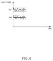
- FIG. 4 is a graph showing the power of the multi-wavelength lights shown in FIG. 3 input to the semiconductor optical amplifier
- FIG. 5 is a graph showing the power of the multi-wavelength lights shown in FIG. 3 amplified by the semiconductor optical amplifier
- FIG. 6 is a block diagram showing a construction of a wavelength division multiplexing system according to a second aspect of the present invention.
- FIG. 7 is a block diagram showing a construction of a wavelength division multiplexing system according to a third aspect of the present invention.
- FIG. 1 is a perspective view of a multi-wavelength light source according to a first aspect of the present invention, which includes a fabry-perot laser and a semiconductor optical amplifier integrated on a single-substrate.
- the multi-wavelength light source 100 according to the first aspect of the present invention includes a substrate 110 , a fabry-perot laser 120 driven by driving current below threshold current, and the semiconductor optical amplifier (hereinafter, referred to as a SOA) 130 .
- the multi-wavelength light source 100 has a high reflection layer 101 coated on a first surface of the multi-wavelength light source 100 including an end surface of the fabry-perot laser 120 .
- the multi-wavelength light source 100 has anti-reflection layers, which are coated on a side surface 120 a of the fabry-perot laser 120 opposed to the SOA 130 , a slant surface 130 a of the SOA 130 opposed to the fabry-perot laser 120 , and a second end surface 102 of the multi-wavelength light source 100 including one surface of the SOA 130 , respectively.
- the fabry-perot laser 120 is laminated on the substrate 110 and is operated by driving current below a predetermined threshold current, thereby causing the output of multi-wavelength light including a plurality of peaks whose wavelengths and spacing are identical to these of WDM channels,
- the SOA 130 is laminated on the substrate 110 in such a manner that end surfaces 120 a and 130 a of the fabry-perot laser 120 and the SOA 130 are opposed to each other.
- the arrangement of the opposing ends of the SOA and the fabry-perot laser permit the amplifying of the multi-wavelength light output from the fabry-perot laser 120 .
- FIG. 2 is a plan view of the multi-wavelength light source shown in FIG. 1 .
- the end surface 130 a of the SOA 130 opposed to end surface 120 a of the fabry-perot laser 120 is inclined with respect to a predetermined angle, with thereby preventing the multi-wavelength light output from the fabry-perot laser 120 from being reflected from the SOA 130 to the fabry-perot laser 120 .
- a band gap of the SOA 130 is smaller than that of the fabry-perot laser 120 , so that a spectrum of the multi-wavelength light output from the fabry-perot laser 120 coincides with a gain spectrum that can be amplified by the SOA 130 .
- the anti-reflection layers are coated on the slant surface 130 a of the SOA 130 , which is opposed to the fabry-perot laser 120 , and the side surface 120 a of the fabry-perot laser 120 opposed to the SOA 130 .
- the peak wavelengths of output channels as well as the intervals between the outputted channels are determined according to the length of the fabry-perot laser 120 . Accordingly, when the multi-wavelength light source shown in FIG. 2 is employed in the wavelength division multiplexing system, the length of the fabry-perot laser 120 is adjusted, so that wavelengths of channels and intervals between the channels can be adjusted, which are necessary for the wavelength division multiplexing system.
- FIG. 3 is a graph of a gain curve showing correlation between the power of multi-wavelength lights input to the SOA shown in FIG. 1 , and power of the multi-wavelength lights amplified by the SOA.
- FIG. 4 shows the power of the multi-wavelength lights inputted to the SOA shown in FIG. 1
- FIG. 5 shows the power of the multi-wavelength lights amplified by the SOA shown in FIG. 1 .
- an operation characteristic of the multi-wavelength light source shown in FIG. 1 according to the first embodiment of the present invention will be described with reference to FIGS. 3 to 5 .
- the gain curve of the SOA shown in FIG. 3 shows variation of the power of the multi-wavelength lights 310 , 320 input to and amplified by the SOA versus the output values 311 , 321 , respectively.
- the graph has a linear region and a gain saturation region. In the linear region, as the power of the multi-wavelength lights input to the SOA increases, the power of the amplified multi-wavelength light output gradually increases. In the gain saturation region, the output power doesn't increase even if the input power is increased gradually.
- FIG. 4 is a graph showing the power of the multi-wavelength lights 310 , 320 input to the SOA 130 shown in FIG. 1 .
- the multi-wavelength lights are output from the fabry-perot laser 120 .
- First multi-wavelength light 310 (which is shown in FIG. 3 ) has power that corresponds to the gain saturation region of the SOA, which is larger than the power of second multi-wavelength light 320 .
- the second multi-wavelength light 320 is amplified in the linear region of the SOA instead of the gain saturation region because the second multi-wavelength light has less power than the first multi-wavelength light 310 .
- the first and the second multi-wavelength lights 310 and 320 include a plurality of channels having different wavelengths, and the power of each channel (as shown by pins 1 and 2 in FIG. 4 ) varies over time. This characteristic is referred to as power fluctuation, and is generally not desirable.
- FIG. 5 is a graph showing the output power of the multi-wavelength lights after being amplified by the SOA 130 shown in FIG. 1 .
- pins 1 and 2 represent the respective output power of multi-wavelength lights 310 and 320 after amplification by the SOA. It can be seen that pin 1 output power, although being larger than that of pin 2 , has a lower amount of power fluctuation.
- the power of the amplified multi-wavelength lights increases in proportion to the power of the input multi-wavelength lights. Therefore, it can be shown from FIG. 5 the different in power fluctuation of the second multi-wavelength light 320 inputted to the SOA versus the first multi-wavelength light 310 .
- first multi-wavelength light 310 is input to the gain saturation region (shown in FIG. 3 ), wherein the output power is almost constant as the input power is varying, the power fluctuation of the multiple channels included in first multi-wavelength light is also reduced.
- the power of the multi-wavelength light outputted from the fabry-perot laser 120 shown in FIG. 1 has power included in the gain saturation region of the SOA, so that the power fluctuation of the multi-wavelength light is also reduced. Furthermore, the reduction of the power fluctuation decreases relative intensity noise.
- FIG. 6 is a block diagram showing a wavelength division multiplexed communication system including a multi-wavelength light source according to a second embodiment of the present invention.
- the wavelength division multiplexed communication system includes a central office 200 outputting multi-wavelength light, a remote node 230 connected to the central office 200 through an optical fiber, and a plurality of subscribers 240 - 1 to 240 - n connected to the remote node 230 .
- the central office 200 includes a light source section 210 for generating multi-wavelength light comprising the fabry-perot laser 211 and the SOA 212 , wherein the output of the light source section 211 is demultiplexed by, a demultiplexer 220 , a plurality of modulators 201 - 1 to 201 - n for modulating the respective multiplexed signals individually, a plurality of photodetectors 203 - 1 to 203 - n for detecting upstream channels sent by subscribers via the remote node 230 and demultiplexed by a first Mux/Demux 221 and a plurality of wavelength selection couplers 202 - 1 to 202 - n.
- the light source section 210 includes a laser 211 and a semiconductor optical amplifier (hereinafter, referred to as a SOA) 212 .
- the laser 211 is operated by driving current below a predetermined threshold current so as to generate the multi-wavelength light including a plurality of downstream channels having different wavelengths.
- the SOA 212 amplifies the multi-wavelength light in a gain saturation state so as to output the amplified light. Therefore, the light source section 210 amplifies the multi-wavelength light while reducing relative intensity noise of the downstream channels of the multi-wavelength light.
- a fabry-perot laser, etc. can be used as the laser 211 , and while preferred, is not required.
- the demultiplexer 220 demultiplexes the multi-wavelength light generated by the light source section 210 into a plurality of downstream channels 205 having different wavelengths, and outputs the demultiplexed downstream channels to the modulators 201 - 1 to 201 - n .
- An arrayed waveguide grating, etc., can be used as the demultiplexer 220 .
- the first multiplexer/demultiplexer 221 demultiplexes an upstream optical signal outputted from the remote node 230 into a plurality of upstream channels having different wavelengths, and outputs the demultiplexed upstream channels to the photodetectors 203 - 1 to 203 - n . Further, the first multiplexer/demultiplexer 221 multiplexes the downstream channels modulated by the modulators 201 - 1 ⁇ 201 - n into a downstream optical signal, and outputs the multiplexed optical signal to the remote node 230 .
- the photodetectors 203 - 1 to 203 - n detect the upstream channels that are demultiplexed by the first multiplexer/demultiplexer 221 , and they include light-receiving type active elements such as photo diodes, etc.
- the wavelength selection couplers 202 - 1 to 202 - n outputs the downstream channels modulated by the modulators 201 - 1 to 201 - n to the first multiplexer/demultiplexer 221 , and outputs the upstream channels, which are output from the first multiplexer/demultiplexer 221 , to a corresponding photodetector 203 - 1 or 203 - n.
- the remote node 230 includes a second multiplexer/demultiplexer 231 , so that the remote node 230 multiplexes a plurality of upstream channels having different wavelengths, which are output from the subscribers 240 - 1 to 240 - n , into an upstream optical signal, and outputs the multiplexed optical signal to the central office 200 . Further, the remote node 230 demultiplexes the downstream optical signal output from the central office 200 into a plurality of downstream channels, and outputs the demultiplexed downstream channels to the subscribers 240 - 1 to 240 - n.
- Each of the subscribers 240 - 1 to 240 - n includes a photodetector 242 , a light source 243 , and a wavelength selection coupler 241 .
- the wavelength selection coupler 241 outputs the downstream channel, which is output from the remote node 230 , to the photodetector 242 , and outputs an upstream channel generated by the light source 243 to the remote node 230 .
- the photodetector 242 detects a corresponding downstream channel outputted from the remote node 230 , and includes a photo diode, etc.
- the light source 243 outputs the upstream channel to the wavelength selection coupler 241 , and includes a semiconductor laser, etc.
- FIG. 7 is a block diagram showing a construction of a wavelength division multiplexing system according to a third aspect of the present invention.
- the wavelength division multiplexing system includes a central office 300 generating a downstream optical signal, a remote node 340 demultiplexing the downstream optical signal into a plurality of downstream channels having different wavelengths, and a plurality of subscribers 350 - 1 to 350 - n connected to the remote node 340 .
- the central office 300 includes a plurality of light sources 313 - 1 to 313 - n for generating mode-locked downstream channels, a plurality of photodetectors 311 - 1 to 311 - n for detecting upstream channels, a first multiplexer/demultiplexer 312 , a downstream broadband light source 330 , an upstream broadband light source 320 , an optical coupler 310 , and wavelength selection couplers 314 - 1 to 314 - n.
- Each of the light sources 313 - 1 to 313 - n generates mode-locked downstream channels having different wavelengths by corresponding incoherent light.
- Each of the photodetectors 311 - 1 to 311 - n detects a corresponding upstream channel outputted from the first multiplexer/demultiplexer 312 .
- Each of the wavelength selection couplers 314 - 1 to 314 - n outputs incoherent lights, which are outputted from the first multiplexer/demultiplexer 312 , to the light sources 313 - 1 to 313 - n , and outputs the upstream channels, which are outputted from the first multiplexer/demultiplexer 312 , to the photodetectors 311 - 1 to 311 - n . Further, each of the wavelength selection couplers 314 - 1 to 314 - n outputs the downstream channels generated by the light sources 313 - 1 to 313 - n to the first multiplexer/demultiplexer 312 .
- the downstream broadband light source 330 includes a first laser 333 for generating downstream light, a first semiconductor optical amplifier 332 , and a first isolator 331 , so that the downstream broadband light source 330 enables the light sources 313 - 1 to 313 - n to generate the mode-locked downstream channels.
- the first laser 333 can use a fabry-perot laser and is driven by driving current below threshold current, so that the first laser 333 generates downstream light, which includes a plurality of incoherent lights having different wavelengths, for mode-locking the light sources 313 - 1 to 313 - n.
- the first semiconductor optical amplifier 332 amplifies the downstream light, which is generated by the first laser 333 , in a gain saturation state, thereby reducing power fluctuation of the downstream light and relative intensity noise of the downstream light due to the power fluctuation.
- the first isolator 331 is connected to the optical coupler 310 , so that the first isolator 331 outputs the downstream light, which is amplified by the first semiconductor optical amplifier 332 , to the optical coupler 310 , and reflects an upstream optical signal, which is outputted from the optical coupler 310 , to the optical coupler 310 .
- the upstream broadband light source 320 includes a second laser 323 for generating upstream light, a second semiconductor optical amplifier 322 , and a second isolator 321 , and outputs upstream light, which includes a plurality of incoherent lights, for mode-locking the subscribers 350 - 1 to 350 - n.
- the second laser 323 can use a fabry-perot laser and is driven by driving current below threshold current, so that the second laser 323 generates upstream light, which includes a plurality of incoherent lights having different wavelengths, for mode-locking the subscribers 350 - 1 to 350 - n.
- the first semiconductor optical amplifier 322 amplifies the upstream light, which is generated by the second laser 323 , in a gain saturation state, thereby reducing power fluctuation of the upstream light and relative intensity noise of the upstream light due to the power fluctuation.
- the second isolator 321 is connected to the optical coupler 310 , so that it outputs the upstream light, which is amplified by the second semiconductor optical amplifier 322 , to the optical coupler 310 , and reflects a downstream optical signal, which is outputted from the optical coupler 310 , to the optical coupler 310 .
- the first multiplexer/demultiplexer 312 demultiplexes the downstream light generated by the downstream broadband light source 330 into a plurality of incoherent lights so as to output the demultiplexed incoherent lights to the wavelength selection couplers 314 - 1 to 314 - n . Further, the first multiplexer/demultiplexer 312 multiplexes the downstream channels generated by the light sources 313 - 1 to 313 - n into a downstream optical signal so as to output the multiplexed optical signal to the optical coupler 310 .
- the first multiplexer/demultiplexer 312 demultiplexes the upstream optical signal outputted from the optical coupler 310 into upstream channels having different wavelengths so as to output the demultiplexed upstream channels to the photodetectors 311 - 1 to 311 - n.
- the optical coupler 310 outputs the downstream light and the upstream optical signal to the first multiplexer/demultiplexer 312 , and outputs the upstream light and the downstream optical signal to the remote node 340 .
- the remote node 340 includes a second multiplexer/demultiplexer 341 .
- the multiplexer/demultiplexer 341 demultiplexes the downstream optical signal outputted from the optical coupler 310 into downstream channels having different wavelengths so as to output the demultiplexed downstream channels to the subscribers 350 - 1 to 350 - n .
- the second multiplexer/demultiplexer 341 multiplexes a plurality of upstream channels having different wavelengths generated by the subscribers 350 - 1 to 350 - n into an upstream optical signal so as to output the multiplexed optical signal to the central office 300 .
- the second multiplexer/demultiplexer 341 demultiplexes the upstream light outputted from the central office 300 into a plurality of incoherent lights having different wavelengths so as to output the demultiplexed incoherent lights to the subscribers 350 - 1 to 350 - n.
- Each of the subscribers 350 - 1 to 350 - n includes a light source 353 , and a photodetector 352 , and a wavelength selection coupler 351 .
- the light source 353 generates a mode-locked upstream channel by corresponding incoherent light
- the photodetector 352 detects a corresponding downstream channel.
- the wavelength selection coupler 351 outputs the downstream channel, which is outputted from the remote node 340 , to the photodetector 352 , and outputs the incoherent light to the light source 353 . Further, the wavelength selection coupler 351 outputs the mode-locked upstream channel generated by the light source 353 to the remote node 340 .
- the light source 353 includes a fabry-perot laser, etc.
- the photodetector 352 includes a photo diode, etc.
- a fabry-perot laser is driven by driving current below threshold current so as to generate multi-wavelength light including a plurality of channels having different wavelengths. Further, the generated multi-wavelength light is amplified by a semiconductor optical amplifier, which has been driven by high driving current and in a gain saturation state, so as to generate a multi-wavelength light in which a gain of each channel is maintained constant.
- multi-wavelength light source of the present invention multi-wavelength light having a plurality of channels different from each other, which is generated in a fabry-perot laser before a laser resonance, is amplified by a semiconductor optical amplifier in a gain saturation state, so that power fluctuation of each channel is reduced, and thus relative intensity noise is also reduced. Further, a semiconductor optical amplifier and a fabry-perot laser are easily integrated, so that a multi-wavelength light source having a miniaturized size can be manufactured, and the manufacturing cost is reduced.
Abstract
Description
Claims (11)
Applications Claiming Priority (2)
| Application Number | Priority Date | Filing Date | Title |
|---|---|---|---|
| KR2003-60191 | 2003-08-29 | ||
| KR10-2003-0060191A KR100539928B1 (en) | 2003-08-29 | 2003-08-29 | Multi-wavelength light source and wavelength division multiplexing system using the same |
Publications (2)
| Publication Number | Publication Date |
|---|---|
| US20050047727A1 US20050047727A1 (en) | 2005-03-03 |
| US7224519B2 true US7224519B2 (en) | 2007-05-29 |
Family
ID=34214744
Family Applications (1)
| Application Number | Title | Priority Date | Filing Date |
|---|---|---|---|
| US10/798,662 Expired - Fee Related US7224519B2 (en) | 2003-08-29 | 2004-03-11 | Low noise multi-wavelength light source and wavelength division multiplexing system using same |
Country Status (4)
| Country | Link |
|---|---|
| US (1) | US7224519B2 (en) |
| JP (1) | JP2005079588A (en) |
| KR (1) | KR100539928B1 (en) |
| CN (1) | CN1302330C (en) |
Cited By (10)
| Publication number | Priority date | Publication date | Assignee | Title |
|---|---|---|---|---|
| US20060051103A1 (en) * | 2004-09-08 | 2006-03-09 | Ranganath Tirumala R | Multi-channel fabry-perot laser transmitters and methods of generating multiple modulated optical signals |
| US20080131141A1 (en) * | 2006-11-30 | 2008-06-05 | Ranganath Tirumala R | Parallel channel optical communication using modulator array and shared laser |
| US20080232807A1 (en) * | 2006-05-19 | 2008-09-25 | Chang-Hee Lee | Wavelength Division Multiplexed-Passive Optical Network Capable of High-Speed Transmission of an Optical Signal By Using Modulation Format Having High Spectral Efficiency |
| US20100092175A1 (en) * | 2008-10-10 | 2010-04-15 | Electronics And Telecommunications Research Institute | Reflective semiconductor optical amplifier and optical signal processing method using the same |
| US20120300290A1 (en) * | 2011-05-24 | 2012-11-29 | Sumitomo Electric Industries, Ltd. | Pulsed light source |
| US20130094074A1 (en) * | 2011-10-14 | 2013-04-18 | Mehdi Asghari | Gain medium providing laser and amplifier functionality to optical device |
| US20130308178A1 (en) * | 2012-05-17 | 2013-11-21 | Finisar Corporation | Co-modulation of DBR Laser and Integrated Optical Amplifier |
| US20140098412A1 (en) * | 2012-10-05 | 2014-04-10 | Volcano Corporation | Systems and methods for amplifying light |
| US20140153083A1 (en) * | 2012-11-30 | 2014-06-05 | Massachusetts Institute Of Technology | Rin reduced optical source for optical coherence tomography |
| US10613273B2 (en) * | 2017-05-19 | 2020-04-07 | Mellanox Technologies, Ltd. | Optical component assembly and waveguide loopback |
Families Citing this family (24)
| Publication number | Priority date | Publication date | Assignee | Title |
|---|---|---|---|---|
| WO2004084607A2 (en) | 2003-03-19 | 2004-10-07 | Binoptics Corporation | High smsr unidirectional etched lasers and low back-reflection photonic device |
| KR100609698B1 (en) * | 2004-06-09 | 2006-08-08 | 한국전자통신연구원 | Wavelength division multiplexing passive optical network and optical source generating method |
| JP2006270283A (en) * | 2005-03-23 | 2006-10-05 | Fujitsu Ltd | Wavelength division multiplex transmission apparatus using multiple wavelength optical source |
| KR100720113B1 (en) * | 2005-08-29 | 2007-05-18 | 한국과학기술원 | The wavelength-division multiplexed passive optical network for reducing the degraded noise performance of wavelength-locked Fabry-Perot laser diodes |
| WO2007065614A2 (en) * | 2005-12-07 | 2007-06-14 | Innolume Gmbh | Laser source with broadband spectrum emission |
| US7835408B2 (en) * | 2005-12-07 | 2010-11-16 | Innolume Gmbh | Optical transmission system |
| US7561607B2 (en) * | 2005-12-07 | 2009-07-14 | Innolume Gmbh | Laser source with broadband spectrum emission |
| US7489440B2 (en) * | 2006-10-19 | 2009-02-10 | International Business Machines Corporation | Optical spectral filtering and dispersion compensation using semiconductor optical amplifiers |
| WO2010065731A2 (en) | 2008-12-03 | 2010-06-10 | Innolume Gmbh | Semiconductor laser with low relative intensity noise of individual longitudinal modes and optical transmission system incorporating the laser |
| KR20100092853A (en) * | 2009-02-13 | 2010-08-23 | 한국과학기술원 | A transmission device of low-noise light signals having a low-noise multi-wavelength light source, a transmission device of broadcast signals using a low-noise multi-wavelength light source, and an optical access network having the same |
| JP2011258703A (en) * | 2010-06-08 | 2011-12-22 | Furukawa Electric Co Ltd:The | Control method of wavelength variable laser element and wavelength variable laser device |
| WO2012034563A1 (en) | 2010-09-14 | 2012-03-22 | Danmarks Tekniske Universitet | Laser system with wavelength converter |
| US9685755B2 (en) | 2012-03-13 | 2017-06-20 | Danmarks Tekniske Universitet | Laser system with wavelength converter |
| EP2878045B1 (en) | 2012-07-27 | 2020-01-08 | Thorlabs, Inc. | Polarization stable widely tunable short cavity laser |
| TWI578653B (en) * | 2015-05-04 | 2017-04-11 | 中華電信股份有限公司 | A novel optical amplifier for optical networks |
| US20160337041A1 (en) * | 2015-05-15 | 2016-11-17 | Futurewei Technologies, Inc. | Polarization Independent Reflective Modulator |
| WO2016194556A1 (en) | 2015-05-29 | 2016-12-08 | 浜松ホトニクス株式会社 | Light source device and inspection device |
| EP3513440A4 (en) * | 2016-09-14 | 2020-09-09 | Nokia Technologies Oy | Optical detection apparatus and method |
| US10551640B2 (en) | 2016-11-21 | 2020-02-04 | Futurewei Technologies, Inc. | Wavelength division multiplexed polarization independent reflective modulators |
| US10222676B2 (en) | 2017-01-27 | 2019-03-05 | Futurewei Technologies, Inc. | Polarization insensitive integrated optical modulator |
| US10330959B2 (en) | 2017-05-22 | 2019-06-25 | Futurewei Technologies, Inc. | Polarization insensitive micro ring modulator |
| US10243684B2 (en) | 2017-05-23 | 2019-03-26 | Futurewei Technologies, Inc. | Wavelength-division multiplexed polarization-insensitive transmissive modulator |
| GB2580956B (en) * | 2019-01-31 | 2023-01-25 | Exalos Ag | Amplified Spontaneous Emission Semiconductor Source |
| US11929592B2 (en) * | 2020-09-17 | 2024-03-12 | Marvell Asia Pte Ltd. | Silicon-photonics-based semiconductor optical amplifier with N-doped active layer |
Citations (35)
| Publication number | Priority date | Publication date | Assignee | Title |
|---|---|---|---|---|
| US3484713A (en) * | 1964-04-03 | 1969-12-16 | Gen Electric | Two-stage semiconductor coherent radiation source |
| US3504302A (en) * | 1964-09-24 | 1970-03-31 | Gen Electric | Frequency controlled semiconductor junction laser |
| JPS62199086A (en) | 1986-02-26 | 1987-09-02 | Fujitsu Ltd | Semiconductor light emitting device |
| US4957339A (en) * | 1988-06-08 | 1990-09-18 | Alcatel N.V. | Optical communication system, particularly in the subscriber area |
| JPH03163891A (en) | 1989-11-21 | 1991-07-15 | Mitsubishi Electric Corp | Light amplifier, super-luminescent diode and optical integrated circuit and their manufacture |
| US5103456A (en) * | 1990-07-30 | 1992-04-07 | Spectra Diode Laboratories, Inc. | Broad beam laser diode with integrated amplifier |
| US5202780A (en) * | 1989-04-22 | 1993-04-13 | Alcatel N.V. | Optical communication system for the subscriber area |
| JPH05206570A (en) | 1992-01-28 | 1993-08-13 | Nippondenso Co Ltd | Wavelength multiplex light source |
| US5260960A (en) * | 1991-07-26 | 1993-11-09 | Siemens Aktiengesellschaft | Tunable semiconductor laser on a semi-insulating substrate |
| US5371757A (en) * | 1993-10-22 | 1994-12-06 | The United States Of America As Represented By The Secretary Of The Air Force | Integrated semiconductor laser oscillator and off-axis amplifier |
| US5394261A (en) * | 1990-09-25 | 1995-02-28 | Canon Kabushiki Kaisha | Optical communication system and transmitting apparatus for use therein |
| US5517232A (en) * | 1993-07-10 | 1996-05-14 | Alcatel Sel Aktiengesellschaft | Cable television distribution network with video-on-demand transmission |
| US5550666A (en) * | 1994-06-17 | 1996-08-27 | Lucent Technologies Inc. | Wavelength division multiplexed multi-frequency optical source and broadband incoherent optical source |
| US5568311A (en) * | 1994-05-30 | 1996-10-22 | Mitsubishi Denki Kabushiki Kaisha | Wavelength tunable semiconductor laser device |
| US5790580A (en) * | 1994-09-16 | 1998-08-04 | Nec Corporation | Semiconductor optical integrated device |
| US5808764A (en) * | 1995-12-28 | 1998-09-15 | Lucent Technologies, Inc. | Multiple star, passive optical network based on remote interrogation of terminal equipment |
| US5808767A (en) * | 1996-05-30 | 1998-09-15 | Bell Atlantic Network Services, Inc | Fiber optic network with wavelength-division-multiplexed transmission to customer premises |
| US5864413A (en) * | 1996-02-23 | 1999-01-26 | Lucent Technologies, Inc. | Passive optical network for dense WDM downstream data transmission and upstream data transmission |
| US5914978A (en) * | 1993-01-07 | 1999-06-22 | Sdl, Inc. | Semiconductor gain medium with multimode and single mode regions |
| US5926297A (en) * | 1996-09-03 | 1999-07-20 | Fujitsu Limited | Optical modulating device and optical modulating method |
| US6141477A (en) * | 1997-01-10 | 2000-10-31 | Nec Corporation | Semiconductor optical amplification element |
| US20010015839A1 (en) * | 1999-12-30 | 2001-08-23 | Samsung Electronic Co., Ltd. | Optical cross-connect device with transparency |
| US20010015836A1 (en) * | 1999-12-28 | 2001-08-23 | Samsung Electronic Co., Ltd. | Node structure of upgradable wavelength division multiplexing system |
| US20010030785A1 (en) * | 2000-02-23 | 2001-10-18 | Pangrac David M. | System and method for distributing information via a communication network |
| US20010055138A1 (en) * | 2000-03-09 | 2001-12-27 | Richardson David John | Optical transmission system and method |
| US20020080454A1 (en) * | 2000-12-26 | 2002-06-27 | Schemmann Marcel F.C. | Method, system and apparatus for optically transferring information |
| JP2002270949A (en) | 2001-03-12 | 2002-09-20 | Atr Adaptive Communications Res Lab | Optical wavelength splitting multiple signal generator |
| US20020154372A1 (en) * | 2001-04-24 | 2002-10-24 | Chung Yeun Chol | Power and optical frequency monitoring system and transmission system of frequency-modulated optical signal |
| US20030030859A1 (en) * | 2000-09-19 | 2003-02-13 | Ji-Wook Youn | Optical performance monitoring apparatus for a WDM optical communication system |
| US20030067676A1 (en) * | 2001-10-04 | 2003-04-10 | Gazillion Bits, Inc. | Semiconductor optical amplifier using laser cavity energy to amplify signal and method of fabrication thereof |
| JP2003134058A (en) | 2001-08-15 | 2003-05-09 | Nippon Telegr & Teleph Corp <Ntt> | Optical communication system, optical communication unit, and optical transmitter/receiver |
| WO2003063401A2 (en) | 2002-01-21 | 2003-07-31 | Novera Optics, Inc. | Methods and apparatuses to provide a wavelength division-multiplexing passive optical network based on wavelength-locked wavelenght-division- multiplexed light sources |
| US20030210724A1 (en) * | 2002-03-04 | 2003-11-13 | Ungar Jeffrey E. | De-tuned distributed feedback laser diode |
| US20030219054A1 (en) * | 2002-05-24 | 2003-11-27 | Lucent Technologies, Inc. | Optical amplifier for quantum cascade laser |
| US20060024066A1 (en) * | 2003-06-19 | 2006-02-02 | Masamichi Fujiwara | Optical modulating device |
Family Cites Families (3)
| Publication number | Priority date | Publication date | Assignee | Title |
|---|---|---|---|---|
| US6134250A (en) * | 1998-05-14 | 2000-10-17 | Lucent Technologies Inc. | Wavelength-selectable fiber ring laser |
| US6014237A (en) * | 1998-06-01 | 2000-01-11 | Sarnoff Corporation | Multiwavelength mode-locked dense wavelength division multiplexed optical communication systems |
| KR100459924B1 (en) * | 2001-10-30 | 2004-12-03 | 광주과학기술원 | Phased array antenna using gain switched multimode Fabry-Perot laser diode and highly dispersive fiber |
-
2003
- 2003-08-29 KR KR10-2003-0060191A patent/KR100539928B1/en not_active IP Right Cessation
-
2004
- 2004-03-11 US US10/798,662 patent/US7224519B2/en not_active Expired - Fee Related
- 2004-04-21 CN CNB2004100368912A patent/CN1302330C/en not_active Expired - Fee Related
- 2004-08-27 JP JP2004247760A patent/JP2005079588A/en active Pending
Patent Citations (37)
| Publication number | Priority date | Publication date | Assignee | Title |
|---|---|---|---|---|
| US3484713A (en) * | 1964-04-03 | 1969-12-16 | Gen Electric | Two-stage semiconductor coherent radiation source |
| US3504302A (en) * | 1964-09-24 | 1970-03-31 | Gen Electric | Frequency controlled semiconductor junction laser |
| JPS62199086A (en) | 1986-02-26 | 1987-09-02 | Fujitsu Ltd | Semiconductor light emitting device |
| US4957339A (en) * | 1988-06-08 | 1990-09-18 | Alcatel N.V. | Optical communication system, particularly in the subscriber area |
| US5202780A (en) * | 1989-04-22 | 1993-04-13 | Alcatel N.V. | Optical communication system for the subscriber area |
| JPH03163891A (en) | 1989-11-21 | 1991-07-15 | Mitsubishi Electric Corp | Light amplifier, super-luminescent diode and optical integrated circuit and their manufacture |
| US5103456A (en) * | 1990-07-30 | 1992-04-07 | Spectra Diode Laboratories, Inc. | Broad beam laser diode with integrated amplifier |
| US5394261A (en) * | 1990-09-25 | 1995-02-28 | Canon Kabushiki Kaisha | Optical communication system and transmitting apparatus for use therein |
| US5260960A (en) * | 1991-07-26 | 1993-11-09 | Siemens Aktiengesellschaft | Tunable semiconductor laser on a semi-insulating substrate |
| JPH05206570A (en) | 1992-01-28 | 1993-08-13 | Nippondenso Co Ltd | Wavelength multiplex light source |
| US5914978A (en) * | 1993-01-07 | 1999-06-22 | Sdl, Inc. | Semiconductor gain medium with multimode and single mode regions |
| USRE37051E1 (en) * | 1993-01-07 | 2001-02-13 | Sdl, Inc. | Semiconductor gain medium with multimode and single mode regions |
| US5517232A (en) * | 1993-07-10 | 1996-05-14 | Alcatel Sel Aktiengesellschaft | Cable television distribution network with video-on-demand transmission |
| US5371757A (en) * | 1993-10-22 | 1994-12-06 | The United States Of America As Represented By The Secretary Of The Air Force | Integrated semiconductor laser oscillator and off-axis amplifier |
| US5568311A (en) * | 1994-05-30 | 1996-10-22 | Mitsubishi Denki Kabushiki Kaisha | Wavelength tunable semiconductor laser device |
| US5550666A (en) * | 1994-06-17 | 1996-08-27 | Lucent Technologies Inc. | Wavelength division multiplexed multi-frequency optical source and broadband incoherent optical source |
| US5790580A (en) * | 1994-09-16 | 1998-08-04 | Nec Corporation | Semiconductor optical integrated device |
| US5808764A (en) * | 1995-12-28 | 1998-09-15 | Lucent Technologies, Inc. | Multiple star, passive optical network based on remote interrogation of terminal equipment |
| US5864413A (en) * | 1996-02-23 | 1999-01-26 | Lucent Technologies, Inc. | Passive optical network for dense WDM downstream data transmission and upstream data transmission |
| US5864415A (en) * | 1996-05-30 | 1999-01-26 | Bell Atlantic Network Services, Inc. | Fiber optic network with wavelength-division-multiplexed transmission to customer premises |
| US5808767A (en) * | 1996-05-30 | 1998-09-15 | Bell Atlantic Network Services, Inc | Fiber optic network with wavelength-division-multiplexed transmission to customer premises |
| US5926297A (en) * | 1996-09-03 | 1999-07-20 | Fujitsu Limited | Optical modulating device and optical modulating method |
| US6141477A (en) * | 1997-01-10 | 2000-10-31 | Nec Corporation | Semiconductor optical amplification element |
| US20010015836A1 (en) * | 1999-12-28 | 2001-08-23 | Samsung Electronic Co., Ltd. | Node structure of upgradable wavelength division multiplexing system |
| US20010015839A1 (en) * | 1999-12-30 | 2001-08-23 | Samsung Electronic Co., Ltd. | Optical cross-connect device with transparency |
| US20010030785A1 (en) * | 2000-02-23 | 2001-10-18 | Pangrac David M. | System and method for distributing information via a communication network |
| US20010055138A1 (en) * | 2000-03-09 | 2001-12-27 | Richardson David John | Optical transmission system and method |
| US20030030859A1 (en) * | 2000-09-19 | 2003-02-13 | Ji-Wook Youn | Optical performance monitoring apparatus for a WDM optical communication system |
| US20020080454A1 (en) * | 2000-12-26 | 2002-06-27 | Schemmann Marcel F.C. | Method, system and apparatus for optically transferring information |
| JP2002270949A (en) | 2001-03-12 | 2002-09-20 | Atr Adaptive Communications Res Lab | Optical wavelength splitting multiple signal generator |
| US20020154372A1 (en) * | 2001-04-24 | 2002-10-24 | Chung Yeun Chol | Power and optical frequency monitoring system and transmission system of frequency-modulated optical signal |
| JP2003134058A (en) | 2001-08-15 | 2003-05-09 | Nippon Telegr & Teleph Corp <Ntt> | Optical communication system, optical communication unit, and optical transmitter/receiver |
| US20030067676A1 (en) * | 2001-10-04 | 2003-04-10 | Gazillion Bits, Inc. | Semiconductor optical amplifier using laser cavity energy to amplify signal and method of fabrication thereof |
| WO2003063401A2 (en) | 2002-01-21 | 2003-07-31 | Novera Optics, Inc. | Methods and apparatuses to provide a wavelength division-multiplexing passive optical network based on wavelength-locked wavelenght-division- multiplexed light sources |
| US20030210724A1 (en) * | 2002-03-04 | 2003-11-13 | Ungar Jeffrey E. | De-tuned distributed feedback laser diode |
| US20030219054A1 (en) * | 2002-05-24 | 2003-11-27 | Lucent Technologies, Inc. | Optical amplifier for quantum cascade laser |
| US20060024066A1 (en) * | 2003-06-19 | 2006-02-02 | Masamichi Fujiwara | Optical modulating device |
Non-Patent Citations (2)
| Title |
|---|
| Lasing threshold. Wikipedia, the free encyclopedia. Multiple Editors/Authors. Uploaded: Dec. 6, 2005. Downloaded: Jan. 11, 2006. http://en.wikipedia.org/w/index.php?title=Lasing<SUB>-</SUB>threshold&oldid=30321671. * |
| Spectral linewidth. Wikipedia, the free encyclopedia. Multiple Editors/Authors. Uploaded: Nov. 2, 2005. Downloaded: Jan. 11, 2006. http://en.wikipedia.org/w/index.php?title=Spectral<SUB>-</SUB>linewidth&oldid=27157822. * |
Cited By (20)
| Publication number | Priority date | Publication date | Assignee | Title |
|---|---|---|---|---|
| US7747174B2 (en) * | 2004-09-08 | 2010-06-29 | Avago Technologies Fiber Ip (Singapore) Pte. Ltd. | Multi-channel fabry-perot laser transmitters and methods of generating multiple modulated optical signals |
| US20060051103A1 (en) * | 2004-09-08 | 2006-03-09 | Ranganath Tirumala R | Multi-channel fabry-perot laser transmitters and methods of generating multiple modulated optical signals |
| US8442400B2 (en) | 2006-05-19 | 2013-05-14 | Korea Advanced Institute Of Science And Technology | Wavelength division multiplexed-passive optical network capable of high-speed transmission of an optical signal by using modulation format having high spectral efficiency |
| US20080232807A1 (en) * | 2006-05-19 | 2008-09-25 | Chang-Hee Lee | Wavelength Division Multiplexed-Passive Optical Network Capable of High-Speed Transmission of an Optical Signal By Using Modulation Format Having High Spectral Efficiency |
| US8078061B2 (en) * | 2006-05-19 | 2011-12-13 | Korea Advanced Institute Of Science And Technology | Wavelength division multiplexed-passive optical network capable of high-speed transmission of an optical signal by using modulation format having high spectral efficiency |
| US7734189B2 (en) | 2006-11-30 | 2010-06-08 | Avago Technologies Fiber Ip (Singapore) Pte. Ltd. | Parallel channel optical communication using modulator array and shared laser |
| US20080131141A1 (en) * | 2006-11-30 | 2008-06-05 | Ranganath Tirumala R | Parallel channel optical communication using modulator array and shared laser |
| US8149503B2 (en) * | 2008-10-10 | 2012-04-03 | Electronics And Telecommunications Research Institute | Reflective semiconductor optical amplifier and optical signal processing method using the same |
| US20100092175A1 (en) * | 2008-10-10 | 2010-04-15 | Electronics And Telecommunications Research Institute | Reflective semiconductor optical amplifier and optical signal processing method using the same |
| US9001416B2 (en) * | 2011-05-24 | 2015-04-07 | Megaopto Co., Ltd. | Pulsed light source |
| US20120300290A1 (en) * | 2011-05-24 | 2012-11-29 | Sumitomo Electric Industries, Ltd. | Pulsed light source |
| US9025241B2 (en) * | 2011-10-14 | 2015-05-05 | Kotura, Inc. | Gain medium providing laser and amplifier functionality to optical device |
| US20130094074A1 (en) * | 2011-10-14 | 2013-04-18 | Mehdi Asghari | Gain medium providing laser and amplifier functionality to optical device |
| US20130308178A1 (en) * | 2012-05-17 | 2013-11-21 | Finisar Corporation | Co-modulation of DBR Laser and Integrated Optical Amplifier |
| US9231367B2 (en) * | 2012-05-17 | 2016-01-05 | Finisar Corporation | Co-modulation of DBR laser and integrated optical amplifier |
| US9831631B2 (en) | 2012-05-17 | 2017-11-28 | Finisar Corporation | Directly modulated laser for PON application |
| US20140098412A1 (en) * | 2012-10-05 | 2014-04-10 | Volcano Corporation | Systems and methods for amplifying light |
| US9478940B2 (en) * | 2012-10-05 | 2016-10-25 | Volcano Corporation | Systems and methods for amplifying light |
| US20140153083A1 (en) * | 2012-11-30 | 2014-06-05 | Massachusetts Institute Of Technology | Rin reduced optical source for optical coherence tomography |
| US10613273B2 (en) * | 2017-05-19 | 2020-04-07 | Mellanox Technologies, Ltd. | Optical component assembly and waveguide loopback |
Also Published As
| Publication number | Publication date |
|---|---|
| US20050047727A1 (en) | 2005-03-03 |
| CN1302330C (en) | 2007-02-28 |
| JP2005079588A (en) | 2005-03-24 |
| CN1591154A (en) | 2005-03-09 |
| KR20050023117A (en) | 2005-03-09 |
| KR100539928B1 (en) | 2005-12-28 |
Similar Documents
| Publication | Publication Date | Title |
|---|---|---|
| US7224519B2 (en) | Low noise multi-wavelength light source and wavelength division multiplexing system using same | |
| KR100480246B1 (en) | Passive optical network using loop back of multi-wavelength light generated at central office | |
| US7073956B1 (en) | Optical transceiver and passive optical network using the same | |
| EP1695466B1 (en) | Integration of laser sources and detectors for a passive optical network | |
| US7515626B2 (en) | Light source capable of lasing that is wavelength locked by an injected light signal | |
| KR100575983B1 (en) | Multi-wavelength optical transmitter and wavelength division multiplexing system usng the same | |
| US6996138B2 (en) | Fabry-Perot laser apparatus mode-locked to multi-frequency lasing light source and optical transmission apparatus using the same | |
| US8639119B2 (en) | Remote node for wavelength-division-multiplexed passive optical network | |
| US7596319B2 (en) | Wavelength division multiplexing-passive optical network system | |
| US7398021B2 (en) | Optical transmitter and passive optical network using the same | |
| US20110188859A1 (en) | Wdm-pon architecture based on externally seeded optical source | |
| US7271949B2 (en) | Multi-wavelength light source and wavelength division multiplexing system using the same | |
| US8538262B2 (en) | Color free WDM PON based on broadband optical transmitters | |
| JP4109296B2 (en) | Central base station and wavelength division multiplexing passive optical network using the same | |
| US20100322624A1 (en) | Bidirectional transmission network apparatus based on tunable rare-earth-doped fiber laser | |
| JP2006526307A (en) | Light source capable of laser oscillation that is wavelength-locked by the injected optical signal | |
| KR100734829B1 (en) | Apparatus and method of transmitting light | |
| KR100575948B1 (en) | Optical transmitter module and wavelength division multiplexing source for using the same | |
| US20110110665A1 (en) | Anti-reflection coated quantum dot resonator for wavelength division multiplexing optical communication | |
| EP2408125B1 (en) | Optical transmitter for wdm passive optical network | |
| KR20070084966A (en) | Wdm-pon system using light emitting diode and optical transceiver for the same | |
| KR100547721B1 (en) | Optical amplifier module and optical transmission system using same | |
| KR20050069472A (en) | Wavelength division multiplexing - passive optical network system |
Legal Events
| Date | Code | Title | Description |
|---|---|---|---|
| AS | Assignment |
Owner name: SAMSUNG ELECTRONICS CO., LTD., KOREA, REPUBLIC OF Free format text: ASSIGNMENT OF ASSIGNORS INTEREST;ASSIGNORS:SHIN, HYUN-CHEOL;LEE, JEONG-SEOK;HWANG, SEONG-TAEK;AND OTHERS;REEL/FRAME:015080/0044 Effective date: 20040302 |
|
| AS | Assignment |
Owner name: SAMSUNG ELECTRONICS CO., LTD., KOREA, REPUBLIC OF Free format text: CORRECTIVE ASSIGNMENT TO CORRECT THE SPELLING OF THE FOURTH CONVEYING PARTY'S NAME PREVIOUSLY RECORDED AT REEL 015080 FRAME 0044;ASSIGNORS:SHIN, HYUN-CHEOL;LEE, JEONG-SEOK;HWANG, SEONG-TAEK;AND OTHERS;REEL/FRAME:015812/0169 Effective date: 20040303 |
|
| AS | Assignment |
Owner name: SAMSUNG ELECTRONICS CO., LTD., KOREA, REPUBLIC OF Free format text: CORRECTIVE ASSIGNMENT TO CORRECT THE ASSIGNOR'S EXECUTION DATES FROM 3/3/04 TO 3/2/04. DOCUMENT PREVIOUSLY RECORDED AT REEL 015812 FRAME 0169;ASSIGNORS:SHIN, HYUN-CHEOL;LEE, JEONG-SEOK;HWANG, SEONG-TAEK;AND OTHERS;REEL/FRAME:016512/0911 Effective date: 20040302 |
|
| STCF | Information on status: patent grant |
Free format text: PATENTED CASE |
|
| FEPP | Fee payment procedure |
Free format text: PAYOR NUMBER ASSIGNED (ORIGINAL EVENT CODE: ASPN); ENTITY STATUS OF PATENT OWNER: LARGE ENTITY |
|
| FPAY | Fee payment |
Year of fee payment: 4 |
|
| FPAY | Fee payment |
Year of fee payment: 8 |
|
| FEPP | Fee payment procedure |
Free format text: PAYER NUMBER DE-ASSIGNED (ORIGINAL EVENT CODE: RMPN); ENTITY STATUS OF PATENT OWNER: LARGE ENTITY Free format text: PAYOR NUMBER ASSIGNED (ORIGINAL EVENT CODE: ASPN); ENTITY STATUS OF PATENT OWNER: LARGE ENTITY |
|
| FEPP | Fee payment procedure |
Free format text: MAINTENANCE FEE REMINDER MAILED (ORIGINAL EVENT CODE: REM.); ENTITY STATUS OF PATENT OWNER: LARGE ENTITY |
|
| LAPS | Lapse for failure to pay maintenance fees |
Free format text: PATENT EXPIRED FOR FAILURE TO PAY MAINTENANCE FEES (ORIGINAL EVENT CODE: EXP.); ENTITY STATUS OF PATENT OWNER: LARGE ENTITY |
|
| STCH | Information on status: patent discontinuation |
Free format text: PATENT EXPIRED DUE TO NONPAYMENT OF MAINTENANCE FEES UNDER 37 CFR 1.362 |
|
| FP | Lapsed due to failure to pay maintenance fee |
Effective date: 20190529 |