US7706428B2 - Low complexity inter-carrier interference cancellation - Google Patents
Low complexity inter-carrier interference cancellation Download PDFInfo
- Publication number
- US7706428B2 US7706428B2 US11/350,807 US35080706A US7706428B2 US 7706428 B2 US7706428 B2 US 7706428B2 US 35080706 A US35080706 A US 35080706A US 7706428 B2 US7706428 B2 US 7706428B2
- Authority
- US
- United States
- Prior art keywords
- ici
- samples
- time
- carrier
- sub
- Prior art date
- Legal status (The legal status is an assumption and is not a legal conclusion. Google has not performed a legal analysis and makes no representation as to the accuracy of the status listed.)
- Expired - Fee Related, expires
Links
Images


Classifications
-
- H—ELECTRICITY
- H04—ELECTRIC COMMUNICATION TECHNIQUE
- H04L—TRANSMISSION OF DIGITAL INFORMATION, e.g. TELEGRAPHIC COMMUNICATION
- H04L27/00—Modulated-carrier systems
- H04L27/26—Systems using multi-frequency codes
-
- H—ELECTRICITY
- H04—ELECTRIC COMMUNICATION TECHNIQUE
- H04L—TRANSMISSION OF DIGITAL INFORMATION, e.g. TELEGRAPHIC COMMUNICATION
- H04L27/00—Modulated-carrier systems
- H04L27/26—Systems using multi-frequency codes
- H04L27/2601—Multicarrier modulation systems
- H04L27/2647—Arrangements specific to the receiver only
-
- H—ELECTRICITY
- H04—ELECTRIC COMMUNICATION TECHNIQUE
- H04B—TRANSMISSION
- H04B15/00—Suppression or limitation of noise or interference
-
- H—ELECTRICITY
- H04—ELECTRIC COMMUNICATION TECHNIQUE
- H04L—TRANSMISSION OF DIGITAL INFORMATION, e.g. TELEGRAPHIC COMMUNICATION
- H04L25/00—Baseband systems
- H04L25/02—Details ; arrangements for supplying electrical power along data transmission lines
- H04L25/03—Shaping networks in transmitter or receiver, e.g. adaptive shaping networks
- H04L25/03006—Arrangements for removing intersymbol interference
- H04L25/03821—Inter-carrier interference cancellation [ICI]
-
- H—ELECTRICITY
- H04—ELECTRIC COMMUNICATION TECHNIQUE
- H04L—TRANSMISSION OF DIGITAL INFORMATION, e.g. TELEGRAPHIC COMMUNICATION
- H04L25/00—Baseband systems
- H04L25/02—Details ; arrangements for supplying electrical power along data transmission lines
- H04L25/0202—Channel estimation
- H04L25/0212—Channel estimation of impulse response
- H04L25/0216—Channel estimation of impulse response with estimation of channel length
-
- H—ELECTRICITY
- H04—ELECTRIC COMMUNICATION TECHNIQUE
- H04L—TRANSMISSION OF DIGITAL INFORMATION, e.g. TELEGRAPHIC COMMUNICATION
- H04L27/00—Modulated-carrier systems
- H04L27/26—Systems using multi-frequency codes
- H04L27/2601—Multicarrier modulation systems
- H04L27/2602—Signal structure
- H04L27/2605—Symbol extensions, e.g. Zero Tail, Unique Word [UW]
- H04L27/2607—Cyclic extensions
Definitions
- the present invention relates to digital communication where Orthogonal Frequency Division Multiplexing (OFDM) is employed, and more particularly to cancellation of inter-carrier interference between OFDM sub-carriers.
- OFDM Orthogonal Frequency Division Multiplexing
- a signal comprises a number of sub-carriers that are independently modulated, each by its own data.
- the modulation can be in accordance with a number of well-known techniques, such as Quadrature Amplitude Modulation (QAM) or n-ary Phase Shift Keying (n-PSK).
- QAM Quadrature Amplitude Modulation
- n-PSK n-ary Phase Shift Keying
- the baseband signal in an OFDM system is then the sum of these modulated sub-carriers.
- the baseband signal is then used to modulate a main radio frequency (RF) signal.
- RF radio frequency
- An important aspect of demodulating such a signal involves processing it by a Fast Fourier Transform (FFT).
- FFT Fast Fourier Transform
- cyclic prefix The way to handle large delay spreads for a system based on OFDM is to make use of a guard interval, often referred to in the literature as a “cyclic prefix”, (“CP”).
- the CP is simply a copy of the last part of an OFDM symbol that is sent before the actual symbol. This is schematically illustrated in FIG. 1 , which shows a number of symbols.
- An exemplary one of the symbols 101 includes a last portion 103 that is transmitted as a preceding cyclic prefix 105 (time flows from left to right in the figure).
- Other cyclic prefixes are similarly formed from end portions of their immediately succeeding symbols.
- ISI inter-symbol interference
- the length (i.e., duration) of the CP is at least as long as the (maximum) duration of the impulse response of the channel.
- SFN Single Frequency Networks
- OFDM is also becoming the choice for other types of wireless communications systems. It is used for Wireless Local Area Networks (WLAN), Broadband Access (Wi-Max), Digital Video Broadcasting (DVB), Digital Audio Broadcasting (DAB), and it has been proposed for the fourth generation (4G) of mobile communications equipment.
- WLAN Wireless Local Area Networks
- Wi-Max Broadband Access
- DVD Digital Video Broadcasting
- DAB Digital Audio Broadcasting
- ICI inter-carrier interference
- ICI is caused by lack of orthogonality between the signals received on different sub-carriers. Since the orthogonality is in frequency, things like frequency error, phase noise, and Doppler spread will all cause a loss of orthogonality. The effect of frequency error and phase noise can in theory, and also often in practice, be made small enough by proper design. However, ICI caused by Doppler spread will be present even in an ideal receiver because it is caused by channel variations.
- f c is the carrier frequency
- v is the relative speed between receiver and transmitter
- DVB-H Doppler shifting is an issue for DVB-H systems because DVB-H is designed to be backward compatible with the older DVB-T system, rather than being designed from scratch.
- the DVB-T system was originally designed for receivers with low mobility; in most cases, the receiving antenna is placed on the roof-top of a building, and therefore completely stationary. Since DVB-H is targeting highly mobile devices, one can say that the system is not properly designed.
- the 4k mode introduced in DVB-H (in which the size of the FFT is 4k compared to the 8k FFT that is normally used in DVB-T systems) is an attempt to improve Doppler tolerance for the system.
- the carrier frequency is 1.67 GHz, which is roughly twice the highest frequency under consideration elsewhere for DVB-H.
- the bandwidth of the U.S. system is only 5 MHz. The former means that f D will be at least twice as high for the same vehicle speed, whereas the latter means that the carrier spacing ⁇ f is reduced by a factor of 5 ⁇ 8 compared to the 8 MHz system.
- OFDM performance in Doppler or with frequency offset is improved by using fewer sub-channels. Reducing the number (N) of sub-channels permits a corresponding decrease in the symbol duration. However, this leads to a drop in transmission efficiency because the length of the cyclic prefix cannot be reduced accordingly due to channel delay spread considerations.
- the cyclic prefix length is designed to cover the longest delay spread expected on the channel. As such, in normal operation, this is generally wasteful since the longest delay spread hardly ever occurs.
- One method for improving OFDM Doppler performance is using more robust modulation (e.g., as in DAB).
- Another is adding an additional layer of coding (e.g., as in DVB-H).
- Yet another is introducing a special code for minimum degradation due to ICI, such as repetition coding (transmitting the same data on adjacent sub-channels). All of these schemes suffer from reduced throughput due to the smaller modulation alphabet or the increased coding overhead.
- Other methods include performing ICI cancellation in the receiver.
- a matrix of coefficients is formed describing the ICI coupling into adjacent channels.
- the received signal is then multiplied by the inverse of this matrix to remove the ICI effects.
- the scheme is complex because many sub-carriers contribute to the ICI, especially when the signal to noise requirement is high as it is for high data rate systems using high level modulations, such as 64 QAM.
- ICI inter-carrier interference
- OFDM orthogonal frequency division multiplexing
- the self-interference term is an estimate of the data received at time t on the sub-carrier k ⁇ L, weighted by a rate of change of the channel through which sub-carrier k ⁇ L passes at time t.
- An ICI cancellation coefficient, G L is obtained, wherein the ICI cancellation coefficient, G L , is determined as a function of a window function.
- An estimated ICI term is generated by adjusting the self-interference term, ICI k ⁇ L,k ⁇ L , by an amount based on the ICI cancellation coefficient, G L .
- the estimated ICI term is subtracted from a term representing a signal received on the kth sub-carrier at time t.
- obtaining the ICI cancellation coefficient, G L includes retrieving the ICI cancellation coefficient, G L , from a table stored in a memory device.
- the term representing the signal received on the kth sub-carrier at time t is obtained by applying the window function to the received OFDM signal to generate a set of selected weighted samples, wherein a symbol transmitted on the OFDM signal is represented by N samples; the window function has a size that is greater than N; the set of selected weighted samples comprises a central portion of samples, and at least one of an initial portion of samples and a final portion of samples; and the central portion of samples consists of N samples.
- the window function is a Nyquist window.
- a wrap function is then performed on the set of selected weighted samples to generate a set of N combined weighted samples by, if the set of selected weighted samples includes the initial portion of samples, then combining the initial portion of samples with a like number of samples selected from the central portion of samples, and by, if the set of selected weighted samples includes the final portion of samples, then combining the final portion of samples with a like number of samples selected from the central portion of samples.
- a Fast Fourier Transform is then performed on the N combined weighted samples.
- the window function can conform to any of a great number of alternatives.
- the window function is a 3-step window that begins with a step function that increases from a minimum value to a first intermediate value, stays at the first intermediate value over a first period of time, then increases from the first intermediate value to a second intermediate value, stays at the second intermediate value over a second period of time, then increases from the second intermediate value to a third intermediate value, stays at the third intermediate value over a third period of time, then with another step function increases from the third intermediate value to a maximum value, remains at the maximum value for a fourth period of time, then with a step function decreases from the maximum value to the third intermediate value, remains at the third intermediate value for a fifth period of time, then with a step function decreases from the third intermediate value to the second intermediate value, remains at the second intermediate value for a sixth period of time, then with a step function decreases from the second intermediate value to the first intermediate value, remains at the first intermediate value for a seventh period of time, and then with a
- the ICI cancellation coefficient is determined in accordance with:
- G ⁇ L ( cos ⁇ ( ⁇ ⁇ ⁇ LW ⁇ REL ) ⁇ + ⁇ cos ⁇ ( ⁇ ⁇ ⁇ L ⁇ ⁇ ⁇ W ⁇ REL ⁇ 3 ) 2 ⁇ j ⁇ ⁇ ⁇ ⁇ ⁇ L ) , wherein W REL is a size of a roll-off region of the window-function relative to N.
- the window function is a 1-step window that begins with a step function that increases from a minimum value to an intermediate value, stays at the intermediate value over a first period of time, then with another step function increases from the intermediate value to a maximum value, remains at the maximum value for a second period of time, then with a step function decreases from the maximum value to the intermediate value, remains at the intermediate value for a third period of time, and then with a step function decreases from the intermediate value back to the minimum value.
- the symbol transmitted on the OFDM signal is preceded by a cyclic prefix; and reducing the ICI involves estimating an amount of time dispersion of a channel through which the sub-carrier k passes; and adjusting the size of the window function such that it is greater than N but not large enough to extend into a portion of the cyclic prefix that is affected by the time dispersion of the channel.
- embodiments consistent with the invention include selecting a shape of the window function based on a length of the window function.
- embodiments consistent with the invention include selecting a shape of the window function based on a number of bins being canceled in the OFDM signal received at time t.
- ⁇ circumflex over (D) ⁇ k ⁇ L (t) is determined by using a decision directed technique.
- the self-interference term, ICI k ⁇ L,k ⁇ L is determined in accordance with:
- ICI k - L , k - L ( 1 H ⁇ k - L ⁇ ( t ) ) ⁇ ( D k - L ⁇ ( t ) ⁇ H k - L ⁇ ( t ) ) ⁇ [ ( H ⁇ k - L ⁇ ( t + T N + T cp ) - H ⁇ k - L ⁇ ( t - T N - T cp ) ) 4 ⁇ ( 1 + T cp / T N ) ]
- T N is a time duration corresponding to N samples representing a symbol in the OFDM signal
- T cp is a time duration of a cyclic prefix that precedes the symbol
- ⁇ k ⁇ L (t) is a current channel estimate for sub-carrier k ⁇ L;
- ⁇ k ⁇ L (t+T N +T cp ) is a next channel estimate for sub-carrier k ⁇ L;
- ⁇ k ⁇ L (t ⁇ T N ⁇ T cp ) is a previous channel estimate for sub-carrier k ⁇ L;
- D k ⁇ L (t) is a signal actually transmitted at time t on sub-carrier k ⁇ L;
- H k ⁇ L (t) is an actual channel on sub-carrier k ⁇ L at time t.
- reducing the ICI involves comparing the estimated ICI term with a predetermined Signal-to-Noise Ratio (SNR), and then subtracting the estimated ICI term from the term representing the signal received on the kth sub-carrier at time t only if the comparison of the estimated ICI term with the predetermined SNR satisfies a predetermined criterion.
- SNR Signal-to-Noise Ratio
- FIG. 1 is a schematic illustration of symbols separated by cyclic prefixes in an orthogonal frequency division multiplexing (OFDM) system.
- OFDM orthogonal frequency division multiplexing
- FIG. 2 is a block diagram of a conventional OFDM receiver.
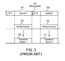
- FIG. 3 is diagram illustrating the operation of a conventional rectangular window function
- FIG. 4 is a block diagram of an exemplary embodiment of an OFDM receiver in accordance with a number of aspects of the invention.
- FIG. 5 is an exemplary process flow diagram illustrating the operation of window and wrap logic.
- FIG. 6A is a flow diagram of operations performed by ICI subtraction logic in accordance with an aspect of the invention.
- FIG. 6B is a flow chart of exemplary operations performed in carrying out the process depicted in FIG. 6A .
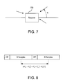
- FIG. 7 shows how a receiver can receive different rays of a signal, each with its own Doppler shift depending on the angle of arrival, ⁇ i , relative to the receiver.
- FIG. 8 illustrates how a difference in successively determined channel estimates is preferably measured from mid-symbol to mid-symbol in some embodiments.
- FIG. 9 illustrates a number of window functions that might be considered for use in OFDM receivers of the type described herein.
- FIG. 10 is a graph showing the results of simulations of the effectiveness of canceling and windowing for different window functions.
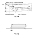
- FIG. 11 is a set of graphs showing the effect of changing the size of the window function.
- FIG. 12 illustrates how, for purposes of determining ICI canceling coefficients, the 3-step window function can be considered as the sum of 4 rectangular pulses, each time shifted.
- FIG. 13 is a table showing cancellation coefficients calculated for a 3-step window function.
- FIG. 14 is a set of graphs showing, for a given amount of ICI cancellation, what combinations of window function size (3-step window function assumed) and number of bins cancelled will achieve that level of cancellation.
- SER Symbol Error Rate
- the invention can additionally be considered to be embodied entirely within any form of computer readable carrier, such as solid-state memory, magnetic disk, optical disk or carrier wave (such as radio frequency, audio frequency or optical frequency carrier waves) containing an appropriate set of computer instructions that would cause a processor to carry out the techniques described herein.
- computer readable carrier such as solid-state memory, magnetic disk, optical disk or carrier wave (such as radio frequency, audio frequency or optical frequency carrier waves) containing an appropriate set of computer instructions that would cause a processor to carry out the techniques described herein.
- any such form of embodiments may be referred to herein as “logic configured to” perform a described action, or alternatively as “logic that” performs a described action.
- a non-rectangular window function is applied to the received signal at the receiver.
- Non-rectangular windowing reduces the ICI problem from frequency offsets and Doppler channels, and at least marginally improves the received signal to noise ratio.
- Non-rectangular windowing is particularly effective when it comes to reducing the ICI from carriers that are relatively far away from the carrier experiencing the interference. That is, by applying windowing, the total ICI experienced is dominated by the very closest sub-carriers. This, in turn, implies that if ICI cancellation is employed, fewer ICI terms need to be cancelled, thereby reducing complexity.
- an adaptive process is used to change the window size.
- the window expands to use up any excess cyclic prefix time, not corrupted by channel delay spread. In this way, a receiver tuned to a channel with low delay spread can make use of the unnecessary portion of the CP to improve its performance in Doppler environments.
- a simplified ICI canceling routine is used.
- the simplified ICI canceling routine takes advantage of the non-rectangular windowing to reduce the number of channels involved in the ICI cancellation. Non-rectangular windowing also reduces the number of correction coefficient values.
- FIG. 2 is a block diagram of a conventional OFDM receiver.
- a digitized received signal, r(n) is subjected to a conventional rectangular window function 201 , which selects N contiguous signal samples corresponding to the duration of one symbol.
- the operation of the conventional rectangular window function 201 is illustrated in FIG. 3 .
- CP 1 cyclic prefix
- CP 2 cyclic prefix
- the conventional rectangular window function 307 takes on one of two possible values, zero and one.
- the rectangular window function 307 acts as a gate: when its value is zero, the corresponding part of the received signal is not selected.
- the window function 307 has a value of one, the corresponding part of the received signal is selected (e.g., allowed to pass through unaffected to the output of the rectangular window function 201 ).
- the duration/length of the non-zero part of the rectangular window function 307 is set equal to the duration of a transmitted symbol, so that N sample points are selected directly from the received signal each time the rectangular window function 307 is applied. In FIG. 3 , this is illustrated as N samples 309 corresponding to Symbol 1 , and N samples 311 corresponding to Symbol 2 .
- the start of the conventional rectangular window function 307 is shown being exactly aligned with the start of each symbol. In practice, it is permissible to start the rectangular window function 307 somewhat earlier (i.e., within the corresponding cyclic prefix for the symbol) so long as the window does not overlap any part of the received signal that has been affected by delay spread (i.e., affected by inter-symbol interference). Starting the conventional rectangular window earlier in this way corresponds to a shift of the N sample points, which may be corrected by known additional processing in the receiver.
- each group of N samples from the conventional rectangular window function 201 is supplied to an N-point Fast Fourier Transform (FFT) unit 203 , which generates a set of coefficients that represent the information being communicated.
- the coefficients are supplied to a channel estimator 205 which uses conventional techniques to generate an estimate of the channel.
- the coefficients are also supplied to an equalizer 207 along with the channel estimate (from the channel estimator 205 ) so that the effects of multi-path propagation can be removed.
- the equalization can be performed by a one-tap per sub channel equalizer.
- FIG. 4 is a block diagram of an exemplary embodiment of an OFDM receiver 400 in accordance with a number of aspects of the invention.
- the exemplary OFDM receiver 400 differs from a conventional receiver in that the received signal, r(n), is supplied to window and wrap logic 401 instead of a conventional rectangular window function.
- the operation of the window and wrap logic 401 will now be described with reference to the exemplary process flow diagram shown in FIG. 5 .
- FIG. 5 shows a signal comprising first and second symbols 301 , 305 and their respective cyclic prefixes CP 1 and CP 2 .
- the window function 501 may differ from the conventional rectangular window in several respects. First, it may take on more than just two values, and is consequently not shaped like a rectangle. For example, the window function 501 increases linearly from its minimum value at zero to its maximum value, remains at its maximum value for some period of time, and then decreases linearly back to its zero.
- this particular window function (which is herein referred to as a “triangle” window) is one of many possible window functions that may be used. The amplitude of the window function at any particular moment weights the corresponding sample that is selected.
- the window function 501 also differs from the conventional rectangular window in that its duration need not be limited to the duration of a symbol. Rather, it is preferred to make the window function 501 longer than the duration of a symbol, but not so long that it will overlap with a portion of the cyclic prefix that is affected by the channel's delay spread.
- the window 501 exceeds the length N of the symbol by an amount W REL ⁇ N, where W REL ⁇ N might be anything from zero to the number of samples in the CP. (This is also the size of the window's “roll-off region”.
- the subscript “REL” is used here to denote that W REL represents the relative size of the roll-off region compared to the length of the symbol.)
- the window function 501 has taken on its maximum permissible duration for the given amount of channel time dispersion. In other embodiments, shorter durations may also be used.
- the set of selected weighted samples 503 comprises three portions: a central portion 505 of N samples, an initial portion 507 , and a final portion 509 . Looking first at the central portion 503 , it will be observed that not all of the N samples are weighted at their maximum values. Rather, some number of first samples and some number of final samples of the N samples are weighted at less than their maximum value.
- the information represented by the first samples of the central portion 505 is identical to the information represented by the final portion 509 of the selected weighted samples 503 .
- the information represented by the final samples of the central portion 505 is identical to the information represented by the initial portion 507 of the selected weighted samples 503 .
- the window function 501 is therefore designed in such a way that the weighted samples from the initial portion 507 may be combined with the weighted samples from the final samples of the central portion 505 to yield a set of combined samples, each weighted at its maximum value (i.e., a Nyquist window is used). Further, the weighted samples from the final portion 509 may be combined with the weighted samples from the initial samples of the central portion 505 to yield a set of combined samples, each weighted at its maximum value. In FIG. 5 , this is illustrated as the N combined samples 511 .
- the window function 501 fulfills the Nyquist condition and is circularly overlapped (wrapped) to obtain the required FFT length of N points. It will be further noted that, in this example, the circular overlapping is symmetric in the sense that the N samples constituting the central portion are in the middle. This is not a requirement, however. An example of a non-symmetric window is also described later in this disclosure.
- an additional feature is provided in which the window size is dynamically adjusted to ensure that the window function 501 does not coincide with a portion of the cyclic prefix affected by the channel's delay spread.
- the received signal, r(n) is supplied to delay spread estimation logic 403 to determine an estimate of the delay spread of the channel.
- delay spread estimation logic 403 There are a number of known ways of performing this estimation, any of which may be used.
- the delay spread estimate is supplied to window size determination logic 405 .
- window size determination logic 405 From an ICI cancellation point of view, it is preferable to use as large a window as possible because this typically gives better performance for the same number of canceled ICI terms; alternatively, a different tradeoff can be made in which fewer ICI terms are canceled while still achieving the same performance as would be obtained with rectangular windowing but with a more complex ICI cancellation scheme.
- a large window can only be used when the maximum delay spread of the channel is significantly smaller than the duration of the cyclic prefix.
- the window size determination logic 405 therefore, utilizes the estimate of the delay spread of the channel to adapt the duration of the window function 501 preferably to make it as large as possible without selecting samples from the cyclic prefix that have been affected by the channel's delay spread. Since an estimate of the delay spread of the channel is often needed anyway (e.g., for channel estimation), the addition of the window size determination logic 405 constitutes only a minimum of extra complexity to the receiver 400 . As shown in FIG. 4 , the window size determination logic 405 dynamically adjusts the operation of the window and wrap logic 401 at least to the extent that the duration of the window used by the window and wrap logic 401 is dynamically adjusted.
- the delay spread of the channel may be estimated after the FFT unit 203 , and a suitable window size then found.
- window size and shape control generation of cancellation coefficients 407 which might be stored in a lookup table or simply calculated within the receiver 400 .
- Cancellation coefficients, G L are supplied to ICI subtraction logic 409 which also receives the output from the FFT unit 203 and the channel estimate from the channel estimation logic 205 .
- the ICI subtraction logic 409 subtracts an estimate of the ICI from the FFT output based on the coefficients, G L , estimates of the transmitted signal, and the rate of change of the channel estimate with respect to time.
- the output from the ICI subtraction logic 409 is then supplied to the equalizer 207 , which operates in a conventional manner.
- the cancellation process starts by first calculating what is herein referred to as a self-interference term, ICI k,k , which is an estimate of the data received at time t on one of the sub-carriers, k, weighted by the (rate of) change of the channel through which sub-carrier k passes at time t.
- the self-interference term will depend on the rate of change of the channel, which throughout will be assumed to be constant during an OFDM symbol.
- the notation H k ′(t) is used herein to denote the change of the channel during one symbol, whose midpoint is at time t.
- H k ′(t) is the change of the channel for one symbol
- the average change of the channel during this symbol compared to what the channel looks like at the start of the symbol is H k ′(t)/2.
- ICI k,k we therefore define the self-interference, ICI k,k as: ICI k,k ⁇ D k ( t ) H k ′( t )/2
- D k (t) is the sent data on carrier k, in practice this can, for example, be estimated as
- D k ⁇ ( t ) ⁇ R k H ⁇ k
- Alternative ways of estimating D k (t) include decision directed approaches as well as estimates derived by minimizing the minimum mean square error (MMSE) of the estimate. These ways of estimating data are, by themselves, known in the art. The use of a decision directed approach will be discussed in more detail later in this disclosure in relation to simulation results.
- MMSE minimum mean square error
- the required logic is further simplified by assuming that the channel changes in a linear way over two or more symbols, so that instead of calculating a derivative term, an average rate of change is simply calculated by determining the difference between channel estimates corresponding to two different moments in time, and dividing by a number representing the time lapse between those two moments. If these approximations are made, one obtains an approximation of the self-interference term given by
- the “4” in the denominator derives from the fact that the expression for ICI k,k has a factor of 2 in the denominator, and the estimate of the change in the channel during one symbol also has a factor of 2 in the denominator due to it being a difference between channel estimates computed over 2 successive symbols.
- Each of the three channel terms is available from the channel estimation logic 205 .
- ⁇ k (t) is the current channel estimate for sub-carrier k
- ⁇ k (t+T N +T cp ) is the next channel estimate
- ⁇ k (t ⁇ T N ⁇ T cp ) is the previous channel estimate.
- the current received signal from the FFT is (D k (t)H k (t)) (with D k (t) being the signal actually transmitted at time t on sub-carrier k, and H k (t) representing the actual channel on sub-carrier k at time t).
- FIG. 6A is a flow diagram of these operations, which are performed by the ICI subtraction logic 409 .
- one or more self-interference terms are generated for neighboring sub-carriers k ⁇ L (L ⁇ [ . . . , ⁇ 3, ⁇ 2, ⁇ 1, 1, 2, 3, . . . ]).
- These self-interference terms are scaled by an amount G L , and then subtracted from the sub-carrier, k, whose interference is to be reduced.
- the inverse channel term is often required in the equalization process, so the division term is not necessarily an extra burden.
- the exemplary process illustrated in FIG. 6A will now be described in greater detail with reference to a flow chart depicted in FIG. 6B .
- the object in this instance is to reduce ICI for the kth sub-carrier.
- the exemplary process begins by generating a self-interference term, ICI k ⁇ L,k ⁇ L , for a signal received on one or more neighboring sub-carriers k ⁇ L, wherein L ⁇ [ . . . , ⁇ 3, ⁇ 2, ⁇ 1, 1, 2, 3, . . .
- the self-interference term is an estimate of the data received at time t on the sub-carrier k ⁇ L, weighted by a rate of change of the channel through which sub-carrier k ⁇ L passes at time t (step 601 ).
- an ICI cancellation coefficient, G L is obtained (step 603 ) that corresponds to the Lth nearest neighbor of sub-carrier k ⁇ L.
- the ICI cancellation coefficient G L may be, for example, read from a previously stored table of such coefficients, or it may be calculated dynamically. As mentioned earlier, the ICI cancellation coefficient, G L , is determined as a function of the window function.
- An estimated ICI term is then generated by adjusting the self-interference term, ICI k ⁇ L,k ⁇ L , by an amount based on the ICI cancellation coefficient, G L (step 605 ).
- the estimated ICI term is subtracted from a term representing a signal received on the kth sub-carrier at time t (step 607 ).
- the number of estimated ICI terms generated from neighboring bins (i.e., the number of values that L takes on) and subtracted from the signal on the kth sub-carrier at time t is application dependent.
- the exp term is caused by the shift of the rectangular time window from a position centered on zero to a position starting at zero (as per the FFT). The slope of this expression is used in the first term of the Taylor expansion to get the ICI value
- ⁇ Y ⁇ ( f ) ⁇ f D k ⁇ H k ⁇ [ ( ⁇ ⁇ ⁇ cos ⁇ ( ⁇ ⁇ ⁇ f ) ( ⁇ ⁇ ⁇ f ) - ⁇ ⁇ ⁇ sin ⁇ ( ⁇ ⁇ ⁇ f ) ( ⁇ ⁇ ⁇ f ) 2 ) ⁇ exp ⁇ ( j ⁇ ⁇ ⁇ ⁇ ⁇ f ) + j ⁇ ⁇ ⁇ ⁇ exp ⁇ ( j ⁇ ⁇ ⁇ ⁇ f ) ⁇ sin ⁇ ( ⁇ ⁇ ⁇ f ) ⁇ ⁇ ⁇ f ]
- FIG. 7 shows how a receiver 700 can receive different rays of a signal, each with its own Doppler shift depending on the angle of arrival, ⁇ i , relative to the receiver 700 .
- Each ray has an associated gain (h i ), phase ( ⁇ i ), delay ( ⁇ i ) and normalized Doppler shift (i.e., the actual Doppler frequency divided by the sub-carrier spacing)
- each ray is substantially constant (quasi-static) during reception of one symbol. It is the phase rotation generated by the Doppler shift that causes fading in time. The effect of each ray will be summed separately.
- H k ⁇ ( t ) ⁇ i ⁇ h i ⁇ exp ( j ⁇ 2 ⁇ ⁇ ⁇ i ⁇ k N + ⁇ i + 2 ⁇ ⁇ i ⁇ t N )
- the channel changes to H k (t+T N +T cp ) (i.e., the new channel estimate in the next time slot).
- the rotation on each path is 2 ⁇ i (N+cp)/N.
- H k ⁇ ( t + T N / 2 ) H k ⁇ ( t ) + [ ( H k ⁇ ( t + T N + T cp ) - H k ⁇ ( t ) ) ( T N + T cp ) ] ⁇ T N 2
- ICI k , k D k ⁇ ( t ) [ ( H k ⁇ ( t + T N + T cp ) - H k ⁇ ( t ) ) ( T N + T cp ) ] ⁇ T N 2
- ICI k , k D k ⁇ ( t ) [ ( H k ⁇ ( t + T N + T cp ) - H k ⁇ ( t - T N - T cp ) ) 2 ⁇ ( T N + T cp ) ] ⁇ T N 2
- ICI k , k R k ⁇ ( t ) H ⁇ k ⁇ ( t ) [ ( H ⁇ k ⁇ ( t + T N + T cp ) - H ⁇ k ⁇ ( t - T N - T cp ) ) 2 ⁇ ( T N + T cp ) ] ⁇ T N 2
- Receiver windowing also reduces ICI, so in some embodiments a suitable window is selected prior to determination of the coefficients G L since, as mentioned above, the coefficients are determined as a function of the type of window being used.
- FIG. 9 illustrates a number of window functions that might be considered for use in OFDM receivers of the type described herein.
- FIG. 10 is a graph showing the results of simulations of the effectiveness of canceling and windowing for different window functions.
- the ICI is caused by frequency offset rather than Doppler shift of the channel.
- frequency error can be seen as a special case of Doppler shift, in which the channel change means that the phase is changed during an OFDM symbol.
- the horizontal axis depicts the number of cancelled bins, with bin 0 representing no cancellation, a first point representing removal of only the fixed phase offset, a point “2” showing the effect of removing the fixed phase offset plus cancellation of the 2 adjacent bins, a point “4” showing the effect of removing the fixed phase offset plus cancellation of the 4 adjacent bins, and so on.
- the top curve shows the effect of using a conventional rectangular window function. The lower the curve, the better the performance. It can be seen from the various graphs that selecting a “best” window function for a given OFDM receiver is dependent on the number of bins that will be cancelled in that receiver. The smoother windows perform better when the number of cancelled bins is large.
- the triangle is best above a point 6 (i.e., removal of the fixed phase offset plus the 6 adjacent bins).
- the 3-step is best for removal of the fixed phase offset plus from 2 to 6 adjacent bins of cancellation and the 1-step is marginally better for the case of no ICI cancellation at all—just removal of the fixed phase offset.
- the 1-step is the best giving a (1 ⁇ W REL /2) noise reduction (0.28 dB in the example of FIG. 10 ).
- W REL i.e., the size of the window roll-off region relative to the size of the symbol
- results depicted in FIG. 10 demonstrate that it can be advantageous to select a shape of the window function based on a length of the window function, and some alternative embodiments include this aspect.
- FIG. 11 is a set of graphs showing the effect of changing the size of the window function.
- the cyclic prefix is assumed to be 25% of the symbol period in this case).
- the horizontal axis depicts the number of cancelled bins, with point 0 representing no cancellation, a first point representing removal of only the fixed phase offset, a point “2” showing the effect of removing the fixed phase offset plus the 2 adjacent bins, a point “4” showing the effect of removing the fixed phase offset plus the 4 adjacent bins, and so on.
- the improvement generally increases also as the window size is made larger.
- the shape of the window function determines the values of the canceling coefficients, G L , that are used by the ICI subtraction logic 409 .
- these coefficients can be determined beforehand and stored in a lookup table. The following is an example that well-illustrates the principles involved in determining the canceling coefficients for a given window function. In this example, a 3-step window function is assumed.
- the 3-step window function can be considered as the sum of four rectangular pulses, each time shifted with respect to the others. This is illustrated in FIG. 12 .
- the value W REL is here expressed relative to the FFT symbol size, which is shown being normalized to a value of 1.0. To avoid complex coefficients the wrap that is performed after the window function is applied (i.e., to generate combined weighted samples) should be between the dotted lines shown in the figure.
- the experienced interference, Y(L), is therefore the sum of the interference associated with each of the rectangular pulses, and is given by:
- G L cos ⁇ ( ⁇ ⁇ ⁇ LW REL ) + cos ⁇ ( ⁇ ⁇ ⁇ L ⁇ ⁇ W REL 3 ) 2 ⁇ j ⁇ ⁇ ⁇ L
- FIG. 14 is a set of graphs showing, for a given amount of ICI cancellation, what combinations of window function size (3-step window function assumed) and number of bins cancelled will achieve that level of cancellation.
- These graphs show that window size can be traded off for canceling complexity, ICI reduction or Doppler performance.
- the information presented in FIG. 14 provides a basis for a set of alternative embodiments in which ICI cancellation is selectively applied based on what SNR is required for the system to work properly and an estimate of the experienced Doppler frequency. For example, if the required SNR is 10 dB, it is known that an ICI level as high as ⁇ 10 dB will be acceptable. Since, in the example of FIG. 14 , it is known that this level of performance can be achieved without ICI cancellation, the ICI cancellation is turned off. If instead, 20 dB is required, then ICI cancellation is turned on to satisfy the receiver's requirements. (This figure is for a fixed f D .) Since the amplitude of the ICI is proportional to the derivative of the channel, practical embodiments can compare the estimated ICI level with the required SNR to dynamically determine whether ICI cancellation should be performed.
- Adaptively changing the window size to utilize the available ISI-free section of the cyclic prefix can lead to a greatly improved performance in Doppler channels, when the delay spread of the channel is low.
- H K , n H _ K + ( n - N - 1 2 ) ⁇ H K ′ N , ( 1 )
- H K ′ is the channel change during the (information part of the) symbol for carrier K
- n is the time index going from 0 to N ⁇ 1. Note that in this case, the average channel during the reception of the OFDM symbol equals H K . Considering the K+Lth bin at the output of the FFT, this equals
- the last step follows from the fact that the different tones are orthogonal if the channel is static, so it is only the varying part that contributes to the ICI. To proceed, we use the fact that if N becomes large, then
- the gain that can be obtained by using a non-rectangular window can also be derived using the sampled signal at the output of the FFT.
- r N ⁇ W ,r N ⁇ W+1 , . . . , r N ⁇ 1 are replaced by r ⁇ W ,r ⁇ W+1 , . . . , r ⁇ 1 , before applying the FFT.
- Folding takes place around sample zero since r 0 is the first sample fed to the FFT.
- the ICI can then be calculated as
- ICI k - L , k S k ⁇ H k ′ ⁇ e - j ⁇ 2 ⁇ ⁇ N ⁇ WL j2 ⁇ ⁇ ⁇ L . ( 9 )
- this exemplary OFDM receiver utilizes both windowing, and ICI cancellation.
- the received signal is first supplied to window and wrap logic 401 , which performs various window operations as described above.
- the N samples generated by the window and wrap logic 401 are supplied to the FFT unit 203 which generates the transmitted data from the modulated signal.
- the channel estimator 205 generates an estimate of the channel, and supplies this to ICI subtraction logic 409 and to an equalizer 207 .
- the ICI subtraction logic 409 uses the channel estimate to generate an estimate of the ICI and to then subtract this ICI estimate from the data supplied by the FFT unit 203 .
- the coefficients, G L , used by the ICI subtraction logic 409 are themselves a function of the window function being used by the window and wrap logic 401 .
- the output of the ICI subtraction logic 409 is then supplied to the equalizer 207 for further processing.
- Simulations were performed to test the above-described techniques for a DVB-T system with an 8k FFT.
- the existence of high Doppler shifts implies that channel estimation will be more difficult, especially in case interpolation in time is used.
- a channel with a relatively short excess delay (1 ⁇ s) was used in the simulations. This allows for channel estimation to be done by directly interpolating between the pilot symbols in the frequency direction.
- FIG. 15 is a set of graphs showing a comparison between simulated effective SNR and theoretical effective SNR for the case of perfect channel estimation.
- the Carrier-to-Noise ratio (C/N) is equal to 100 dB.
- Graph 1501 shows theoretical performance for the case of no windowing applied.
- Graph 1503 shows the results of simulated performance for the case of no windowing applied.
- Graph 1505 shows theoretical performance for the case of windowing being applied.
- Graph 1507 shows the results of simulated performance for the case of windowing being applied.
- Graph 1601 shows theoretical performance for the case of no windowing applied.
- Graph 1603 shows the results of simulated performance for the case of no windowing applied.
- Graph 1605 shows theoretical performance for the case of windowing being applied.
- Graph 1607 shows the results of simulated performance for the case of windowing being applied.
- Graph 1701 shows performance when no windowing and no ICI canceling is performed.
- Graph 1703 shows performance when windowing is performed but no ICI canceling is performed.
- Graph 1705 is a graph showing performance when no windowing is performed but ICI cancellation of 2 bins is performed.
- Graph 1707 is a graph showing performance when windowing is performed and ICI cancellation of 2 bins is performed.
- Graph 1709 is a graph showing performance when no windowing is performed but ICI cancellation of 4 bins is performed.
- Graph 1711 is a graph showing performance when windowing is performed and ICI cancellation of 4 bins is performed.
- Graph 1801 shows performance when no windowing and no ICI canceling is performed.
- Graph 1803 shows performance when windowing is performed but no ICI canceling is performed.
- Graph 1805 is a graph showing performance when no windowing is performed but ICI cancellation of 2 bins is performed.
- Graph 1807 is a graph showing performance when windowing is performed and ICI cancellation of 2 bins is performed.
- Graph 1809 is a graph showing performance when no windowing is performed but ICI cancellation of 4 bins is performed.
- Graph 1811 is a graph showing performance when windowing is performed and ICI cancellation of 4 bins is performed.
- Graph 1901 shows performance when no windowing and no ICI canceling is performed.
- Graph 1903 shows performance when windowing is performed but no ICI canceling is performed.
- Graph 1905 is a graph showing performance when no windowing is performed but ICI cancellation of 2 bins is performed.
- Graph 1907 is a graph showing performance when windowing is performed and ICI cancellation of 2 bins is performed.
- Graph 1909 is a graph showing performance when no windowing is performed but ICI cancellation of 4 bins is performed.
- Graph 1911 is a graph showing performance when windowing is performed and ICI cancellation of 4 bins is performed.
- Graph 2001 shows performance when no windowing and no ICI canceling is performed.
- Graph 2003 shows performance when windowing is performed but no ICI canceling is performed.
- Graph 2005 is a graph showing performance when no windowing is performed but ICI cancellation of 2 bins is performed.
- Graph 2007 is a graph showing performance when windowing is performed and ICI cancellation of 2 bins is performed.
- Graph 2009 is a graph showing performance when no windowing is performed but ICI cancellation of 4 bins is performed.
- Graph 2011 is a graph showing performance when windowing is performed and ICI cancellation of 4 bins is performed.
- Graph 2101 shows performance when no windowing and no ICI canceling is performed.
- Graph 2103 shows performance when windowing is performed but no ICI canceling is performed.
- Graph 2105 is a graph showing performance when no windowing is performed but ICI cancellation of 2 bins is performed.
- Graph 2107 is a graph showing performance when windowing is performed and ICI cancellation of 2 bins is performed.
- Graph 2109 is a graph showing performance when no windowing is performed but ICI cancellation of 4 bins is performed.
- Graph 2111 is a graph showing performance when windowing is performed and ICI cancellation of 4 bins is performed.
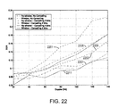
- Graph 2201 shows performance when no windowing and no ICI canceling is performed.
- Graph 2203 shows performance when windowing is performed but no ICI canceling is performed.
- Graph 2205 is a graph showing performance when no windowing is performed but ICI cancellation of 2 bins is performed.
- Graph 2207 is a graph showing performance when windowing is performed and ICI cancellation of 2 bins is performed.
- Graph 2209 is a graph showing performance when no windowing is performed but ICI cancellation of 4 bins is performed.
- Graph 2211 is a graph showing performance when windowing is performed and ICI cancellation of 4 bins is performed.
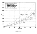
- Graph 2301 shows performance when no windowing and no ICI canceling is performed.
- Graph 2303 shows performance when windowing is performed but no ICI canceling is performed.
- Graph 2305 is a graph showing performance when no windowing is performed but ICI cancellation of 2 bins is performed.
- Graph 2307 is a graph showing performance when windowing is performed and ICI cancellation of 2 bins is performed.
- Graph 2309 is a graph showing performance when no windowing is performed but ICI cancellation of 4 bins is performed.
- Graph 2311 is a graph showing performance when windowing is performed and ICI cancellation of 4 bins is performed.
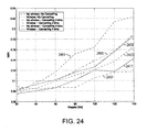
- Graph 2401 shows performance when no windowing and no ICI canceling is performed.
- Graph 2403 shows performance when windowing is performed but no ICI canceling is performed.
- Graph 2405 is a graph showing performance when no windowing is performed but ICI cancellation of 2 bins is performed.
- Graph 2407 is a graph showing performance when windowing is performed and ICI cancellation of 2 bins is performed.
- Graph 2409 is a graph showing performance when no windowing is performed but ICI cancellation of 4 bins is performed.
- Graph 2411 is a graph showing performance when windowing is performed and ICI cancellation of 4 bins is performed.
- some alternative embodiments might further improve ICI canceller performance by using the fact that pilot symbols are known, and not treating them as unknown data.
- channel estimation can further be improved by using higher order filters.
- Better channel estimation in turn means better ICI cancellation, since the channel estimates are used in the ICI cancellation process.
Abstract
Description
where fD=fcv/c is the maximum Doppler frequency, and Δf is the carrier spacing between the sub-carriers. Here, fc is the carrier frequency, v is the relative speed between receiver and transmitter and c=3×10⁸ m/s is the speed of light. When designing an OFDM system, this understanding of ICI can be used to ensure that ICI caused by Doppler effects will not be a problem by making Δf sufficiently large in relation to the expected Doppler shift.
wherein WREL is a size of a roll-off region of the window-function relative to N.
ICI k−L,k−L ={circumflex over (D)} k−L(t)Ĥ k−L′(t)
where {circumflex over (D)}k−L(t) is an estimate of the data transmitted on sub-carrier k−L at time t, and Ĥk−L′(t) is an estimate of the derivative of the channel for sub-carrier k−L at time t. In some of these embodiments, {circumflex over (D)}k−L(t) is determined by using a decision directed technique.
where:
ICI k,k ≡D k(t)H k′(t)/2
where Rk is the actually received data (Rk(t)=Dk(t)Hk(t)) and Ĥk is the estimate of Hk. Alternative ways of estimating Dk(t) include decision directed approaches as well as estimates derived by minimizing the minimum mean square error (MMSE) of the estimate. These ways of estimating data are, by themselves, known in the art. The use of a decision directed approach will be discussed in more detail later in this disclosure in relation to simulation results.
where TN is the time duration corresponding to N samples, and Tcp is the time duration of the cyclic prefix. The “4” in the denominator derives from the fact that the expression for ICIk,k has a factor of 2 in the denominator, and the estimate of the change in the channel during one symbol also has a factor of 2 in the denominator due to it being a difference between channel estimates computed over 2 successive symbols. Each of the three channel terms is available from the
where f is the offset frequency in bins (=L+δ) from the desired bin, k. The exp term is caused by the shift of the rectangular time window from a position centered on zero to a position starting at zero (as per the FFT). The slope of this expression is used in the first term of the Taylor expansion to get the ICI value
Note that since the frequency offset from the kth bin is L+δ in the above derivation, and one in practice is observing the output of bin L, the true frequency offset for the signal has a sign that is opposite that of δ.
change when L goes negative. The self-interference term that occurs (L=0) represents the phase rotation in half a symbol period and is usually included in the channel estimation process.
The amplitude, phase and delay of each ray is substantially constant (quasi-static) during reception of one symbol. It is the phase rotation generated by the Doppler shift that causes fading in time. The effect of each ray will be summed separately.
The channel, Hk(t), for frequency bin k slowly changes due to the Doppler phase rotation on each path
If we assume a linear response between channel measurements:
where the difference ΔHk=Hk(t+TN+Tcp)−Hk(t), which appears in the numerator on the right-hand side of the equation, is preferably measured from mid-symbol to mid-symbol as illustrated in
WindowSize=(1+W REL)N=(1+cp·win)N
where WREL is the size of the window roll-off region, which is here expressed as a fraction, win, of the size of the cyclic prefix (which itself is expressed relative to the size of the symbol, N).
-
- Triangle window: The window begins over an initial period of time by increasing linearly from its minimum value of zero to its maximum value, remains at its maximum value for a time, and then decreases linearly back to zero. This type of window was used as an example in
FIG. 5 . - Raised cosine: The window begins over an initial period of time by increasing from its minimum value of zero to its maximum value in accordance with a raised cosine function, remains at its maximum value for a time, and then decreases from its maximum value back to zero in accordance with a raised cosine function.
- 1-step: The window begins with a step function that increases from a minimum value of zero to an intermediate value, stays at the intermediate value over a first period of time, then with another step function increases from the intermediate value to a maximum value, remains at the maximum value for a second period of time, then with a step function decreases from the maximum value to the intermediate value, remains at the intermediate value for a third period of time, and then with a step function decreases from the intermediate value back to zero.
- 3-step: The window begins with a step function that increases from a minimum value of zero to a first intermediate value, stays at the first intermediate value over a first period of time, then increases from the first intermediate value to a second intermediate value, stays at the second intermediate value over a second period of time, then increases from the second intermediate value to a third intermediate value, stays at the third intermediate value over a third period of time, then with another step function increases from the third intermediate value to a maximum value, remains at the maximum value for a fourth period of time, then with a step function decreases from the maximum value to the third intermediate value, remains at the third intermediate value for a fifth period of time, then with a step function decreases from the third intermediate value to the second intermediate value, remains at the second intermediate value for a sixth period of time, then with a step function decreases from the second intermediate value to the first intermediate value, remains at the first intermediate value for a seventh period of time, and then with a step function decreases from the first intermediate value back to zero.
The invention is not limited to these examples, however; many other window functions not illustrated here may also be used.
- Triangle window: The window begins over an initial period of time by increasing linearly from its minimum value of zero to its maximum value, remains at its maximum value for a time, and then decreases linearly back to zero. This type of window was used as an example in
By similar reasoning as for the case when a rectangular window is used (i.e., by using Taylor expansion), the following expression is obtained for the ICI:
ICI k−L,k =G L ICI k,k
but where now the coefficient GL has been reduced from 1/(jπL) to
These coefficients are shown in a table presented in
where HK′ is the channel change during the (information part of the) symbol for carrier K, and n is the time index going from 0 to
where rn denotes the nth sample of the received signal. Note that ICIK+L is the total signal on bin K+L.
That is, if the channel is not varying then there is no leakage in the FFT.
where the last step follows from the fact that the different tones are orthogonal if the channel is static, so it is only the varying part that contributes to the ICI. To proceed, we use the fact that if N becomes large, then
Consequently, the ICI on carrier k+L caused by the symbol sent on carrier k is given by
Alternatively, by replacing L by −L, we obtain
Defining the self-interference as DkHk′/2, it follows that the same result is obtained as when the ICI terms were derived from assuming the channel being a superposition of frequency offsets.
Straight-forward calculation then gives
Since this can be viewed as an average of Eqns. (6) and (9), we obtain
is merely a phase shift caused by how the folding is done. This phase shift can be avoided by having a symmetric window with respect to the FFT position, that is, by having a symmetric window as in the previous example with a three step window. Finally, to further emphasize the similarity with the previous derivation of the effect of using a non-rectangular window, note that WREL=W/N.
In Table 1, the effect of using the simple window above is given for various values of the normalized window length WREL and number of canceled bins. Here, canceling two bins means that ICI from the two closest bins (one on each side, i.e., L=±1) are cancelled, canceling four bins means that ICI from the four closest bins (two on each side, i.e., L=±1,±2) are cancelled, and so on.
| TABLE 1 |
| Ideal improvement in dB by using different combinations of Window |
| lengths and different complexity in the ICI cancellation. |
| No canceling | 2 |
4 |
6 bins | ||
| WREL = 0 | 0 dB | 4.07 | 6.20 | 7.64 | ||
| WREL = 1/16 | 0.84 | 6.21 | 9.61 | 12.03 | ||
| WREL = 1/8 | 1.73 | 8.16 | 11.15 | 11.74 | ||
| WREL = 3/16 | 2.65 | 9.12 | 9.99 | 10.10 | ||
| WREL = 1/4 | 3.59 | 8.75 | 8.75 | 10.02 | ||
{circumflex over (D)} k =R k /Ĥ k. (12)
-
- Symbol error rate (SER) prior to the FEC decoding. That is, the SER is determined based on the equalized data in the IQ-diagram.
- The SNR in the IQ diagram, where the error is weighted by |ĤK| in order to compensate for the received signal being divided by ĤK when equalizing the channel.
-
- The impact of using a window as the one described by Eqn. (10) of size WREL= 3/16.
- The impact of using a decision directed approach, as described above.
- The impact of the number of canceled bins. Here only three cases were compared: No cancellation, canceling the two closest bins, and canceling four bins.
-
- In case no ICI cancellation is used, the simulated effective SNR agrees reasonably well with that predicted by theory. Here the theoretical effective SNR is defined as
-
- The loss can here be attributed to non-ideal channel estimation.
- The gain in Doppler is about 30%, as predicted by the results in Table 1.
- When ICI cancellation is applied, windowing makes a significant difference.
- If Eqn. (12) is used for estimating the sent signal (i.e., no decision is made), then it seems that increasing the number of canceled bins improves performance, although only marginally when going from 2 to 4 canceled bins.
- When a decision directed approach is taken, it appears that canceling only two bins actually gives better results than canceling four.
- The decision directed approach gives the best results. The reason for this is believed to be not only because the error is zero in case of a correct decision, but also because for the really poor values of Eqn. (12) (i.e., where the estimated signal has a huge amplitude) an erroneous decision can also mean a significant improvement.
Claims (29)
ICI k−L,k−L ={circumflex over (D)} k−L(t)Ĥ k−L′(t)
ICI k−L,k−L ={circumflex over (D)} k−L(t)Ĥ k−L′(t)
Priority Applications (9)
| Application Number | Priority Date | Filing Date | Title |
|---|---|---|---|
| US11/350,807 US7706428B2 (en) | 2005-04-21 | 2006-02-10 | Low complexity inter-carrier interference cancellation |
| TW095113031A TW200705911A (en) | 2005-04-21 | 2006-04-12 | Low complexity inter-carrier interference cancellation |
| DE602006011452T DE602006011452D1 (en) | 2005-04-21 | 2006-04-21 | Time domain windowing and inter-carrier interference cancellation |
| AT06744535T ATE453997T1 (en) | 2005-04-21 | 2006-04-21 | TIME DOMAIN WINDOW TECHNOLOGY AND INTER- CARRIER DISTURBANCE CANCELING |
| EP06744535A EP1872551B1 (en) | 2005-04-21 | 2006-04-21 | Time domain windowing and inter-carrier interference cancellation |
| KR1020077026977A KR20070122572A (en) | 2005-04-21 | 2006-04-21 | Time domain windowing and inter-carrier interference cancellation |
| PCT/IB2006/000962 WO2006111843A1 (en) | 2005-04-21 | 2006-04-21 | Time domain windowing and inter-carrier interference cancellation |
| CN2006800221440A CN101204057B (en) | 2005-04-21 | 2006-04-21 | Time domain windowing and inter-carrier interference cancellation |
| JP2008507187A JP2008537424A (en) | 2005-04-21 | 2006-04-21 | Time domain windowing and intercarrier interference cancellation |
Applications Claiming Priority (2)
| Application Number | Priority Date | Filing Date | Title |
|---|---|---|---|
| US67338405P | 2005-04-21 | 2005-04-21 | |
| US11/350,807 US7706428B2 (en) | 2005-04-21 | 2006-02-10 | Low complexity inter-carrier interference cancellation |
Publications (2)
| Publication Number | Publication Date |
|---|---|
| US20060239367A1 US20060239367A1 (en) | 2006-10-26 |
| US7706428B2 true US7706428B2 (en) | 2010-04-27 |
Family
ID=36715287
Family Applications (1)
| Application Number | Title | Priority Date | Filing Date |
|---|---|---|---|
| US11/350,807 Expired - Fee Related US7706428B2 (en) | 2005-04-21 | 2006-02-10 | Low complexity inter-carrier interference cancellation |
Country Status (9)
| Country | Link |
|---|---|
| US (1) | US7706428B2 (en) |
| EP (1) | EP1872551B1 (en) |
| JP (1) | JP2008537424A (en) |
| KR (1) | KR20070122572A (en) |
| CN (1) | CN101204057B (en) |
| AT (1) | ATE453997T1 (en) |
| DE (1) | DE602006011452D1 (en) |
| TW (1) | TW200705911A (en) |
| WO (1) | WO2006111843A1 (en) |
Cited By (6)
| Publication number | Priority date | Publication date | Assignee | Title |
|---|---|---|---|---|
| US20100008454A1 (en) * | 2008-07-12 | 2010-01-14 | Michael Schnell | Method for compensation of information losses in an OFDM-based multi-carrier communication signal caused by blanking out pulse-shaped interferences |
| CN101917382A (en) * | 2010-08-20 | 2010-12-15 | 华为技术有限公司 | OFDM multi-antenna mapping method and device |
| US20110090971A1 (en) * | 2009-10-20 | 2011-04-21 | Maxlinear, Inc. | Doppler estimator for ofdm systems |
| US8000417B1 (en) * | 2007-11-27 | 2011-08-16 | Samsung Electronics Co., Ltd. | Methods and OFDM receivers providing inter-carrier interference cancellation with guard interval reuse scheme |
| US20140010272A1 (en) * | 2011-02-14 | 2014-01-09 | QUALCOMM Incorpated | Pilot Signal Cancellation Scheme for Mobile Broadband Systems Based on OFDM |
| US10270626B2 (en) | 2014-09-23 | 2019-04-23 | Huawei Technologies Co., Ltd. | Adaptive narrowband interference cancellation method, and apparatus |
Families Citing this family (69)
| Publication number | Priority date | Publication date | Assignee | Title |
|---|---|---|---|---|
| AU2003201483A1 (en) * | 2003-01-15 | 2004-08-10 | Telefonaktiebolaget Lm Ericsson (Publ) | Correlation method for channel estimation for ofdm |
| US8675631B2 (en) | 2005-03-10 | 2014-03-18 | Qualcomm Incorporated | Method and system for achieving faster device operation by logical separation of control information |
| US7590184B2 (en) | 2005-10-11 | 2009-09-15 | Freescale Semiconductor, Inc. | Blind preamble detection for an orthogonal frequency division multiplexed sample stream |
| US7623599B2 (en) * | 2005-11-21 | 2009-11-24 | Freescale Semiconductor, Inc. | Blind bandwidth detection for a sample stream |
| US8948329B2 (en) | 2005-12-15 | 2015-02-03 | Qualcomm Incorporated | Apparatus and methods for timing recovery in a wireless transceiver |
| CN101336533B (en) * | 2006-02-03 | 2012-07-11 | 艾利森电话股份有限公司 | Method, device and method for recovering OFDM signal |
| US7675844B2 (en) * | 2006-02-24 | 2010-03-09 | Freescale Semiconductor, Inc. | Synchronization for OFDM signals |
| JP5046317B2 (en) * | 2006-04-27 | 2012-10-10 | 住友電気工業株式会社 | Receiver, transmitter, transmission system, and transmission method |
| WO2007148796A1 (en) * | 2006-06-23 | 2007-12-27 | Panasonic Corporation | Radio transmitter, radio receiver, and pilot generating method |
| US20080025197A1 (en) * | 2006-07-28 | 2008-01-31 | Mccoy James W | Estimating frequency error of a sample stream |
| EP2057809B1 (en) * | 2006-08-21 | 2010-05-26 | Koninklijke Philips Electronics N.V. | Transmission methods and apparatuses for cancelling inter-carrier interference |
| JP2008109173A (en) | 2006-10-23 | 2008-05-08 | Oki Electric Ind Co Ltd | Fft window extending and generating method |
| US7787358B2 (en) * | 2006-12-19 | 2010-08-31 | Telefonaktiebolaget Lm Ericsson (Publ) | Uplink inter-carrier interference cancellation of OFDMA systems |
| US20080144749A1 (en) * | 2006-12-19 | 2008-06-19 | Leif Wilhelmsson | Inter-Carrier Interference Cancellation for OFDMA Systems |
| US7720183B2 (en) * | 2006-12-28 | 2010-05-18 | Industrial Technology Research Institute | Apparatus and method for inter-carrier interference self-cancellation and inter-carrier interference reconstruction and cancellation |
| US9008198B2 (en) * | 2007-01-05 | 2015-04-14 | Qualcomm Incorporated | Methods and apparatus for timing synchronization based on transitional pilot symbols |
| US7839831B2 (en) * | 2007-01-08 | 2010-11-23 | Qualcomm Incorporated | Methods and apparatus for time tracking using assistance from TDM pilots in a communication network |
| WO2008099572A1 (en) * | 2007-02-15 | 2008-08-21 | Mitsubishi Electric Corporation | Reception device and reception method |
| KR101339425B1 (en) * | 2007-08-27 | 2013-12-09 | 삼성전자주식회사 | Method of estimating Inter-Carrier Interference and ICI mitigating equalizer |
| US7801020B2 (en) * | 2007-08-29 | 2010-09-21 | Intel Corporation | Mobile channel estimation algorithm for DVB-H COFDM demodulator |
| US7773683B2 (en) * | 2007-08-31 | 2010-08-10 | Industrial Technology Research Institute | Method and apparatus for ICI cancellation in communication systems |
| KR101386972B1 (en) * | 2007-10-25 | 2014-04-17 | 한국과학기술원 | Device for determining interference using cyclic prefix and method thereof |
| KR101359628B1 (en) * | 2007-10-25 | 2014-02-06 | 삼성전자주식회사 | Method for Inter-carrier interference cancellation and equalization method, apparatus, and OFDM receiver using the method |
| JP2009111749A (en) | 2007-10-30 | 2009-05-21 | Sony Corp | Reception apparatus, reception method, and program |
| WO2009107078A1 (en) * | 2008-02-25 | 2009-09-03 | Nxp B.V. | Methods, systems and arrangements for frequency shift compensation |
| CN101971536B (en) * | 2008-02-27 | 2015-10-21 | 松下电器产业株式会社 | Receiving system, integrated circuit and method of reseptance |
| WO2009122727A1 (en) * | 2008-03-31 | 2009-10-08 | パナソニック株式会社 | Receiver, method of reception, reception program, integrated circuit, and digital television |
| EP2146470B1 (en) | 2008-07-15 | 2012-02-01 | ST-Ericsson SA | Inter-carrier interference reduction for multi-carrier signals |
| US7664190B1 (en) | 2008-08-04 | 2010-02-16 | Mediatek Inc. | Multi-carrier receiver with dynamic power adjustment and method for dynamically adjusting the power consumption of a multi-carrier receiver |
| CN101789819B (en) * | 2009-01-22 | 2012-11-28 | 北京信威通信技术股份有限公司 | Signal transmission method of multi-aerial system |
| EP2228955B1 (en) * | 2009-03-13 | 2017-02-22 | OCT Circuit Technologies International Limited | System and method for OFDM reception in the presense of Doppler effect based on time domain windowing |
| JP5344429B2 (en) * | 2009-03-24 | 2013-11-20 | ラピスセミコンダクタ株式会社 | FFT window extension generation method |
| TW201039574A (en) * | 2009-04-22 | 2010-11-01 | Ralink Technology Corp | Method of detecting transmission channel and a wireless communication system using the same |
| US8340234B1 (en) * | 2009-07-01 | 2012-12-25 | Qualcomm Incorporated | System and method for ISI based adaptive window synchronization |
| US8693305B2 (en) * | 2009-08-24 | 2014-04-08 | Qualcomm Incorporated | Method and apparatus for detecting OFDM signals in the presence of frequency orthogonal OFDM interferers |
| JP5349206B2 (en) * | 2009-08-28 | 2013-11-20 | 三菱電機株式会社 | Intercarrier interference canceling apparatus and intercarrier interference canceling method |
| US8223862B2 (en) | 2009-10-20 | 2012-07-17 | King Fahd University Of Petroleum And Minerals | OFDM inter-carrier interference cancellation method |
| WO2011067866A1 (en) * | 2009-12-04 | 2011-06-09 | 三菱電機株式会社 | Receiver apparatus and reception method |
| EP2509240B1 (en) * | 2009-12-04 | 2015-11-04 | Mitsubishi Electric Corporation | Receiver devices and receiving methods |
| US8254510B2 (en) * | 2009-12-23 | 2012-08-28 | Industrial Technology Research Institute | Apparatus and method for inter-carrier interference cancellation |
| CN101764783B (en) * | 2010-02-01 | 2012-07-18 | 上海交通大学 | Method for eliminating inter-carrier interference in orthogonal frequency division multiplexing system |
| KR101576914B1 (en) * | 2010-12-30 | 2015-12-11 | 삼성전자주식회사 | Wireless communication system for medical devices using cognitive radio technology |
| CN102291359B (en) * | 2011-09-06 | 2014-08-06 | 复旦大学 | Producing and sending device for enhancing quality of receiving optical OFDM (Orthogonal Frequency Division Multiplexing) signal by adopting time domain windowing technology |
| US9124475B2 (en) * | 2011-09-19 | 2015-09-01 | Alcatel Lucent | Method and apparatus for interference cancellation for antenna arrays |
| JP5789469B2 (en) * | 2011-09-30 | 2015-10-07 | 富士通テン株式会社 | Receiving apparatus and receiving method |
| CN103179059A (en) * | 2011-12-21 | 2013-06-26 | 中兴通讯股份有限公司 | Method and device for eliminating inter-carrier interference (ICI) |
| CN102752253A (en) * | 2011-12-22 | 2012-10-24 | 南京邮电大学 | Method for inhibiting inter-carrier interference of orthogonal frequency division multiplexing (OFDM) system by time-frequency domain combined processing |
| US20130170568A1 (en) * | 2011-12-29 | 2013-07-04 | Assaf Prihed | Reducing inter-carrier interference in ofdm and ofdma systems by time sample scaling based on cyclic prefix samples |
| US9461773B2 (en) * | 2012-08-09 | 2016-10-04 | Stefano Chinnici | Method and a node for detecting phase noise in MIMO communication systems |
| CN103051578B (en) * | 2012-12-04 | 2016-04-06 | 北京工业大学 | With the iteration error propagation judgement OFDM channel estimation method that ICI eliminates |
| US8897412B2 (en) * | 2012-12-14 | 2014-11-25 | Intel Corporation | Method and apparatus for phase noise mitigation |
| US8873655B2 (en) * | 2013-01-10 | 2014-10-28 | Intel Corporation | Sending information at a band edge within an orthogonal frequency-division multiplexing (OFDM) symbol |
| CN104079306B (en) * | 2013-03-26 | 2016-08-03 | 华为技术有限公司 | The operational approach of a kind of receiver and signal receiver |
| US8908796B1 (en) * | 2013-05-15 | 2014-12-09 | University Of South Florida | Orthogonal frequency division multiplexing (OFDM) transmitter and receiver windowing for adjacent channel interference (ACI) suppression and rejection |
| US20150043686A1 (en) * | 2013-08-08 | 2015-02-12 | Amlogic Co., Ltd. | Methods and Systems for Channel Estimation |
| CN106688262B (en) * | 2014-11-03 | 2020-09-11 | 华为技术有限公司 | Processing method and device for eliminating adjacent band interference in wireless system |
| KR102547119B1 (en) * | 2016-01-05 | 2023-06-23 | 삼성전자주식회사 | Method and apparatus for controlling interference in wireless communication system |
| US11125870B2 (en) * | 2016-08-26 | 2021-09-21 | Nec Corporation | Moving-target detection system and moving-target detection method |
| KR102292994B1 (en) * | 2017-03-23 | 2021-08-26 | 삼성전자 주식회사 | Method and apparatus for adjusting a timing in a wireless communication system |
| CN109150446B (en) * | 2017-06-16 | 2021-07-27 | 展讯通信(上海)有限公司 | Time index indicating method, base station, storage medium and electronic device |
| CN109120559B (en) * | 2017-06-22 | 2021-06-29 | 上海数字电视国家工程研究中心有限公司 | Self-adaptive ICI inter-carrier interference elimination method and device |
| CN109120560B (en) * | 2017-06-22 | 2021-06-29 | 上海数字电视国家工程研究中心有限公司 | Self-adaptive ICI inter-carrier interference elimination method and device |
| US10461966B2 (en) * | 2018-02-26 | 2019-10-29 | Samsung Electronics Co., Ltd | System and method for interference cancelation from one numerology on another numerology in mixed numerologies |
| CN109802719B (en) * | 2019-01-03 | 2020-07-17 | 长沙天仪空间科技研究院有限公司 | Satellite communication system based on narrow-band interference suppression |
| EP3809654B1 (en) | 2019-10-14 | 2024-03-20 | Volkswagen AG | Wireless communication device and corresponding apparatus, method and computer program |
| EP3809652B1 (en) * | 2019-10-14 | 2023-12-06 | Volkswagen AG | Wireless communication device and corresponding apparatus, method and computer program |
| EP3809656A1 (en) | 2019-10-14 | 2021-04-21 | Volkswagen AG | Wireless communication device and corresponding apparatus, method and computer program |
| KR20210082891A (en) * | 2019-12-26 | 2021-07-06 | 한국전자통신연구원 | Method for decoding channel using noise level correction in high speed mobilde reception environment and apparatus using the same |
| CN114007176B (en) * | 2020-10-09 | 2023-12-19 | 上海又为智能科技有限公司 | Audio signal processing method, device and storage medium for reducing signal delay |
Citations (14)
| Publication number | Priority date | Publication date | Assignee | Title |
|---|---|---|---|---|
| US5357502A (en) | 1990-02-06 | 1994-10-18 | France Telecom And Telediffusion De France Sa | Device for the reception of digital data time frequency interlacing, notably for radio broadcasting at high bit rate towards mobile receivers with nyquist temporal window |
| US6088327A (en) | 1995-06-07 | 2000-07-11 | Deutsche Thomson-Brandt Gmbh | Method and circuit arrangement for improving carrier separation for the transmission of OFDM signals |
| US20020146063A1 (en) | 2001-02-22 | 2002-10-10 | Alexei Gorokhov | Multicarrier transmission system with reduced complexity leakage matrix multiplication |
| US20020163983A1 (en) | 2001-03-01 | 2002-11-07 | Redferm Arthur John | Receiver window design for multicarrier communication systems |
| US20020181625A1 (en) * | 2001-02-22 | 2002-12-05 | Alexei Gorokhov | Reduced complexity intercarrier interference cancellation |
| US20040022175A1 (en) | 2000-09-12 | 2004-02-05 | Edgar Bolinth | Method and orthogonal frequency division multiplexing (ofdm) receiver for reducing the influence of harmonic interference on ofdm transmission systems |
| US20040151254A1 (en) * | 2002-12-31 | 2004-08-05 | Alcatel | Adaptive inter-carrier interference self-cancellation method and transceiver thereof |
| US20040184550A1 (en) * | 2003-03-20 | 2004-09-23 | Makoto Yoshida | Receiver which demodulates OFDM symbol |
| US20050129136A1 (en) * | 2003-11-11 | 2005-06-16 | Ntt Docomo, Inc. | OFDM receiver |
| US7206349B2 (en) * | 2000-02-22 | 2007-04-17 | Koninklijke Philips Electronics N.V. | Multicarrier receiver with channel estimator |
| US7277512B1 (en) * | 2003-02-20 | 2007-10-02 | Advanced Micro Devices, Inc. | Systems and methods for accounting for intercarrier interference in transmission systems |
| US20080095226A1 (en) * | 2002-12-10 | 2008-04-24 | New Jersey Institute Of Technology | Apparatus for phase noise suppression for ofdm based wlans |
| US20080129136A1 (en) * | 2006-12-01 | 2008-06-05 | Honda Motor Co., Ltd. | Axial gap type motor |
| US20080304585A1 (en) * | 2004-12-28 | 2008-12-11 | Zte Corporation | Method For Suppressing The Inter-Carrier Interference In The Orthogonal Frequency Division Multiplexing Mobile Communication System |
Family Cites Families (2)
| Publication number | Priority date | Publication date | Assignee | Title |
|---|---|---|---|---|
| GB0115015D0 (en) * | 2001-06-20 | 2001-08-08 | Koninkl Philips Electronics Nv | Method of, and receiver for, minimising carrier phase rotation due to signal adjustments and enhancements |
| CN1246983C (en) * | 2003-09-19 | 2006-03-22 | 清华大学 | Sectional demodifying computing method for effectively reducing interfaces between sub-carrier |
-
2006
- 2006-02-10 US US11/350,807 patent/US7706428B2/en not_active Expired - Fee Related
- 2006-04-12 TW TW095113031A patent/TW200705911A/en unknown
- 2006-04-21 DE DE602006011452T patent/DE602006011452D1/en active Active
- 2006-04-21 CN CN2006800221440A patent/CN101204057B/en not_active Expired - Fee Related
- 2006-04-21 EP EP06744535A patent/EP1872551B1/en not_active Not-in-force
- 2006-04-21 KR KR1020077026977A patent/KR20070122572A/en not_active Application Discontinuation
- 2006-04-21 JP JP2008507187A patent/JP2008537424A/en active Pending
- 2006-04-21 AT AT06744535T patent/ATE453997T1/en not_active IP Right Cessation
- 2006-04-21 WO PCT/IB2006/000962 patent/WO2006111843A1/en active Application Filing
Patent Citations (14)
| Publication number | Priority date | Publication date | Assignee | Title |
|---|---|---|---|---|
| US5357502A (en) | 1990-02-06 | 1994-10-18 | France Telecom And Telediffusion De France Sa | Device for the reception of digital data time frequency interlacing, notably for radio broadcasting at high bit rate towards mobile receivers with nyquist temporal window |
| US6088327A (en) | 1995-06-07 | 2000-07-11 | Deutsche Thomson-Brandt Gmbh | Method and circuit arrangement for improving carrier separation for the transmission of OFDM signals |
| US7206349B2 (en) * | 2000-02-22 | 2007-04-17 | Koninklijke Philips Electronics N.V. | Multicarrier receiver with channel estimator |
| US20040022175A1 (en) | 2000-09-12 | 2004-02-05 | Edgar Bolinth | Method and orthogonal frequency division multiplexing (ofdm) receiver for reducing the influence of harmonic interference on ofdm transmission systems |
| US20020146063A1 (en) | 2001-02-22 | 2002-10-10 | Alexei Gorokhov | Multicarrier transmission system with reduced complexity leakage matrix multiplication |
| US20020181625A1 (en) * | 2001-02-22 | 2002-12-05 | Alexei Gorokhov | Reduced complexity intercarrier interference cancellation |
| US20020163983A1 (en) | 2001-03-01 | 2002-11-07 | Redferm Arthur John | Receiver window design for multicarrier communication systems |
| US20080095226A1 (en) * | 2002-12-10 | 2008-04-24 | New Jersey Institute Of Technology | Apparatus for phase noise suppression for ofdm based wlans |
| US20040151254A1 (en) * | 2002-12-31 | 2004-08-05 | Alcatel | Adaptive inter-carrier interference self-cancellation method and transceiver thereof |
| US7277512B1 (en) * | 2003-02-20 | 2007-10-02 | Advanced Micro Devices, Inc. | Systems and methods for accounting for intercarrier interference in transmission systems |
| US20040184550A1 (en) * | 2003-03-20 | 2004-09-23 | Makoto Yoshida | Receiver which demodulates OFDM symbol |
| US20050129136A1 (en) * | 2003-11-11 | 2005-06-16 | Ntt Docomo, Inc. | OFDM receiver |
| US20080304585A1 (en) * | 2004-12-28 | 2008-12-11 | Zte Corporation | Method For Suppressing The Inter-Carrier Interference In The Orthogonal Frequency Division Multiplexing Mobile Communication System |
| US20080129136A1 (en) * | 2006-12-01 | 2008-06-05 | Honda Motor Co., Ltd. | Axial gap type motor |
Non-Patent Citations (9)
| Title |
|---|
| Armstrong, Jean: "Analysis of New and Existing Methods of Reducing Intercarrier Interference Due to Carrier Frequency Offset in OFDM" IEEE Transactions on Communications, IEEE Service Center, Piscataway, NJ, US, vol. 47, No. 3, Mar. 1999, XP011009358. |
| Müller-Weinfurtner, Stefan H.: "Optimum Nyquist Windowing in OFDM Receivers" IEEE Transactions on Communications, vol. 49, No. 3, Mar. 2001. |
| Muschallik, Claus: "Improving an OFDM Reception Using an Adaptive Nyquist Windowing" IEEE Transactions on Consumer Electronics, vol. 42, No. 3, Aug. 1996. |
| PCT International Preliminary Report on Patentability, completed Jun. 21, 2007, in connection with International Patent Application No. PCT/IB2006/000962. |
| PCT International Search Report, dated Aug. 22, 2006, in connection with International Application No. PCT/IB2006/000962. |
| PCT Written Opinion, dated Aug. 22, 2006, in connection with International Application No. PCT/IB2006/000962. |
| Suyama, Satoshi et al.: "A Maximum Likelihood OFDM Receiver with Smoothed FFT-Window for Large Multipath Delay Difference over the Guard Interval" IEEE, VTC, 2002. |
| Suzuki, N. et al.: "A New OFDM Demodulation Method to Reduce Influence of ISI Due to Longer Delay than Guard Interval" Communication Systems, 2002. ICCS 2002. The 8th International Conference on Nov. 25-28, 2002. Piscataway, NJ, USA, IEEE, vol. 1, Nov. 25, 2002, XP010629217. |
| Yang, Hongwei et al. "An Adaptive ICI Self Cancellation Scheme to Compensate the Frequency Offset for OFDM System" Vehicular Technology Conference VTC Spring 2003; Apr. 22-25, 2003, vol. 4, pp. 2658-2662 ISSN 1090-3038. |
Cited By (9)
| Publication number | Priority date | Publication date | Assignee | Title |
|---|---|---|---|---|
| US8000417B1 (en) * | 2007-11-27 | 2011-08-16 | Samsung Electronics Co., Ltd. | Methods and OFDM receivers providing inter-carrier interference cancellation with guard interval reuse scheme |
| US20100008454A1 (en) * | 2008-07-12 | 2010-01-14 | Michael Schnell | Method for compensation of information losses in an OFDM-based multi-carrier communication signal caused by blanking out pulse-shaped interferences |
| US8379780B2 (en) * | 2008-07-12 | 2013-02-19 | Deutsches Zentrum für Luft- und Raumfahrt e.V. | Method for compensation of information losses in an OFDM-based multi-carrier communication signal caused by blanking out pulse-shaped interferences |
| US20110090971A1 (en) * | 2009-10-20 | 2011-04-21 | Maxlinear, Inc. | Doppler estimator for ofdm systems |
| US8897385B2 (en) * | 2009-10-20 | 2014-11-25 | Maxlinear, Inc. | Doppler estimator for OFDM systems |
| CN101917382A (en) * | 2010-08-20 | 2010-12-15 | 华为技术有限公司 | OFDM multi-antenna mapping method and device |
| CN101917382B (en) * | 2010-08-20 | 2013-04-17 | 华为技术有限公司 | OFDM multi-antenna mapping method and device |
| US20140010272A1 (en) * | 2011-02-14 | 2014-01-09 | QUALCOMM Incorpated | Pilot Signal Cancellation Scheme for Mobile Broadband Systems Based on OFDM |
| US10270626B2 (en) | 2014-09-23 | 2019-04-23 | Huawei Technologies Co., Ltd. | Adaptive narrowband interference cancellation method, and apparatus |
Also Published As
| Publication number | Publication date |
|---|---|
| KR20070122572A (en) | 2007-12-31 |
| ATE453997T1 (en) | 2010-01-15 |
| EP1872551A1 (en) | 2008-01-02 |
| EP1872551B1 (en) | 2009-12-30 |
| CN101204057B (en) | 2011-04-06 |
| US20060239367A1 (en) | 2006-10-26 |
| JP2008537424A (en) | 2008-09-11 |
| CN101204057A (en) | 2008-06-18 |
| DE602006011452D1 (en) | 2010-02-11 |
| WO2006111843A1 (en) | 2006-10-26 |
| TW200705911A (en) | 2007-02-01 |
Similar Documents
| Publication | Publication Date | Title |
|---|---|---|
| US7706428B2 (en) | Low complexity inter-carrier interference cancellation | |
| US8345809B2 (en) | Receiver apparatus for receiving a multicarrier signal | |
| US7995688B2 (en) | Channel estimation and ICI cancellation for OFDM | |
| US7554902B2 (en) | Preamble design for frequency offset estimation and channel equalization in burst OFDM transmission system | |
| US7912118B2 (en) | Hybrid domain block equalizer | |
| US7526020B2 (en) | Circuit for improving channel impulse response estimation and compensating for remnant frequency offset in the orthogonal frequency division multiplexing (OFDM) baseband receiver for IEEE 802.11a/g wireless LAN standard | |
| US7099270B2 (en) | Multi-path equalization for orthogonal frequency division multiplexing communication system | |
| US7583755B2 (en) | Systems, methods, and apparatus for mitigation of nonlinear distortion | |
| US7961799B2 (en) | Joint estimation apparatus of channel and frequency offset based on multiband-orthogonal frequency division multiplexing and thereof | |
| KR100610706B1 (en) | Ofdm system receiver apparatus | |
| US7720183B2 (en) | Apparatus and method for inter-carrier interference self-cancellation and inter-carrier interference reconstruction and cancellation | |
| JP4856171B2 (en) | Channel estimation with reduced complexity in OFDM systems | |
| US20110159831A1 (en) | Channel estimation for communication systems with multiple transmit antennas | |
| US8254510B2 (en) | Apparatus and method for inter-carrier interference cancellation | |
| CN101075829B (en) | Method for estimating channel of orthogonal frequency-division multiplexing system | |
| WO2008052732A1 (en) | Subblock-wise frequency domain equalizer | |
| KR100557877B1 (en) | Apparatus and method for channel estimating and ofdm system for the same | |
| Rinne et al. | An improved equalizing scheme for orthogonal frequency division multiplexing systems for time-variant channels | |
| Niranjane et al. | Performance analysis of different channel estimation techniques | |
| KR20080078110A (en) | Apparatus and method for frequency offset compensation in mobile communication system | |
| Zhang et al. | On practical inter-carrier interference cancellation techniques | |
| Lee et al. | Noise-robust channel estimation for DVB-T fixed receptions | |
| Wu et al. | Trade-off between synchronization and decoding in OFDM system | |
| Lv et al. | Blind estimation of symbol timing and carrier frequency offset in time-varying multipath channels for OFDM systems | |
| Kalbasi et al. | Receiver design for mobile OFDM with application to DVB-H |
Legal Events
| Date | Code | Title | Description |
|---|---|---|---|
| AS | Assignment |
Owner name: TELEFONAKTIEBOLAGET LM ERICSSON (PUBL),SWEDEN Free format text: ASSIGNMENT OF ASSIGNORS INTEREST;ASSIGNORS:WILHELMSSON, LEIF;FAULKNER, MICHAEL;SIGNING DATES FROM 20060323 TO 20060328;REEL/FRAME:017569/0588 Owner name: TELEFONAKTIEBOLAGET LM ERICSSON (PUBL), SWEDEN Free format text: ASSIGNMENT OF ASSIGNORS INTEREST;ASSIGNORS:WILHELMSSON, LEIF;FAULKNER, MICHAEL;REEL/FRAME:017569/0588;SIGNING DATES FROM 20060323 TO 20060328 |
|
| STCF | Information on status: patent grant |
Free format text: PATENTED CASE |
|
| CC | Certificate of correction | ||
| FPAY | Fee payment |
Year of fee payment: 4 |
|
| MAFP | Maintenance fee payment |
Free format text: PAYMENT OF MAINTENANCE FEE, 8TH YEAR, LARGE ENTITY (ORIGINAL EVENT CODE: M1552) Year of fee payment: 8 |
|
| FEPP | Fee payment procedure |
Free format text: MAINTENANCE FEE REMINDER MAILED (ORIGINAL EVENT CODE: REM.); ENTITY STATUS OF PATENT OWNER: LARGE ENTITY |
|
| LAPS | Lapse for failure to pay maintenance fees |
Free format text: PATENT EXPIRED FOR FAILURE TO PAY MAINTENANCE FEES (ORIGINAL EVENT CODE: EXP.); ENTITY STATUS OF PATENT OWNER: LARGE ENTITY |
|
| STCH | Information on status: patent discontinuation |
Free format text: PATENT EXPIRED DUE TO NONPAYMENT OF MAINTENANCE FEES UNDER 37 CFR 1.362 |
|
| FP | Lapsed due to failure to pay maintenance fee |
Effective date: 20220427 |