US7801247B2 - Multiple input, multiple output system and method - Google Patents
Multiple input, multiple output system and method Download PDFInfo
- Publication number
- US7801247B2 US7801247B2 US10/144,114 US14411402A US7801247B2 US 7801247 B2 US7801247 B2 US 7801247B2 US 14411402 A US14411402 A US 14411402A US 7801247 B2 US7801247 B2 US 7801247B2
- Authority
- US
- United States
- Prior art keywords
- channel
- symbol
- streams
- matrix
- hacek over
- Prior art date
- Legal status (The legal status is an assumption and is not a legal conclusion. Google has not performed a legal analysis and makes no representation as to the accuracy of the status listed.)
- Expired - Lifetime, expires
Links
- 238000000034 method Methods 0.000 title claims description 27
- 230000009466 transformation Effects 0.000 claims abstract description 41
- 239000011159 matrix material Substances 0.000 claims description 98
- 238000000844 transformation Methods 0.000 claims description 3
- 230000001131 transforming effect Effects 0.000 claims 14
- 230000011664 signaling Effects 0.000 claims 1
- 238000013507 mapping Methods 0.000 abstract description 14
- 239000013598 vector Substances 0.000 description 47
- 238000001514 detection method Methods 0.000 description 37
- 230000000875 corresponding effect Effects 0.000 description 23
- 230000005540 biological transmission Effects 0.000 description 21
- 238000013459 approach Methods 0.000 description 11
- 238000007476 Maximum Likelihood Methods 0.000 description 10
- 238000004891 communication Methods 0.000 description 10
- 238000010586 diagram Methods 0.000 description 6
- 230000007480 spreading Effects 0.000 description 6
- 230000003044 adaptive effect Effects 0.000 description 5
- 238000005562 fading Methods 0.000 description 5
- 230000001413 cellular effect Effects 0.000 description 4
- 230000000694 effects Effects 0.000 description 4
- 238000010606 normalization Methods 0.000 description 4
- 238000012935 Averaging Methods 0.000 description 3
- 230000008901 benefit Effects 0.000 description 3
- 238000006243 chemical reaction Methods 0.000 description 3
- 230000002596 correlated effect Effects 0.000 description 3
- 230000014509 gene expression Effects 0.000 description 3
- 238000013139 quantization Methods 0.000 description 3
- 238000004088 simulation Methods 0.000 description 3
- 238000001228 spectrum Methods 0.000 description 3
- 230000001629 suppression Effects 0.000 description 3
- 230000006978 adaptation Effects 0.000 description 2
- 238000004458 analytical method Methods 0.000 description 2
- 230000008859 change Effects 0.000 description 2
- 230000001934 delay Effects 0.000 description 2
- 230000003111 delayed effect Effects 0.000 description 2
- 238000005192 partition Methods 0.000 description 2
- 230000008569 process Effects 0.000 description 2
- 230000001360 synchronised effect Effects 0.000 description 2
- 238000007792 addition Methods 0.000 description 1
- 230000003321 amplification Effects 0.000 description 1
- 230000009286 beneficial effect Effects 0.000 description 1
- 230000021615 conjugation Effects 0.000 description 1
- 230000003247 decreasing effect Effects 0.000 description 1
- 238000005516 engineering process Methods 0.000 description 1
- PCHJSUWPFVWCPO-UHFFFAOYSA-N gold Chemical compound [Au] PCHJSUWPFVWCPO-UHFFFAOYSA-N 0.000 description 1
- 239000010931 gold Substances 0.000 description 1
- 229910052737 gold Inorganic materials 0.000 description 1
- 238000009499 grossing Methods 0.000 description 1
- 230000006872 improvement Effects 0.000 description 1
- 230000002452 interceptive effect Effects 0.000 description 1
- 230000002045 lasting effect Effects 0.000 description 1
- 238000012986 modification Methods 0.000 description 1
- 230000004048 modification Effects 0.000 description 1
- 238000003199 nucleic acid amplification method Methods 0.000 description 1
- 238000012545 processing Methods 0.000 description 1
- 238000011084 recovery Methods 0.000 description 1
Images


Classifications
-
- H—ELECTRICITY
- H04—ELECTRIC COMMUNICATION TECHNIQUE
- H04B—TRANSMISSION
- H04B7/00—Radio transmission systems, i.e. using radiation field
- H04B7/02—Diversity systems; Multi-antenna system, i.e. transmission or reception using multiple antennas
- H04B7/04—Diversity systems; Multi-antenna system, i.e. transmission or reception using multiple antennas using two or more spaced independent antennas
- H04B7/06—Diversity systems; Multi-antenna system, i.e. transmission or reception using multiple antennas using two or more spaced independent antennas at the transmitting station
- H04B7/0613—Diversity systems; Multi-antenna system, i.e. transmission or reception using multiple antennas using two or more spaced independent antennas at the transmitting station using simultaneous transmission
- H04B7/0615—Diversity systems; Multi-antenna system, i.e. transmission or reception using multiple antennas using two or more spaced independent antennas at the transmitting station using simultaneous transmission of weighted versions of same signal
- H04B7/0619—Diversity systems; Multi-antenna system, i.e. transmission or reception using multiple antennas using two or more spaced independent antennas at the transmitting station using simultaneous transmission of weighted versions of same signal using feedback from receiving side
- H04B7/0621—Feedback content
- H04B7/0634—Antenna weights or vector/matrix coefficients
-
- H—ELECTRICITY
- H04—ELECTRIC COMMUNICATION TECHNIQUE
- H04L—TRANSMISSION OF DIGITAL INFORMATION, e.g. TELEGRAPHIC COMMUNICATION
- H04L1/00—Arrangements for detecting or preventing errors in the information received
- H04L1/02—Arrangements for detecting or preventing errors in the information received by diversity reception
- H04L1/06—Arrangements for detecting or preventing errors in the information received by diversity reception using space diversity
- H04L1/0618—Space-time coding
-
- H—ELECTRICITY
- H04—ELECTRIC COMMUNICATION TECHNIQUE
- H04L—TRANSMISSION OF DIGITAL INFORMATION, e.g. TELEGRAPHIC COMMUNICATION
- H04L25/00—Baseband systems
- H04L25/02—Details ; arrangements for supplying electrical power along data transmission lines
- H04L25/0202—Channel estimation
- H04L25/0204—Channel estimation of multiple channels
-
- H—ELECTRICITY
- H04—ELECTRIC COMMUNICATION TECHNIQUE
- H04L—TRANSMISSION OF DIGITAL INFORMATION, e.g. TELEGRAPHIC COMMUNICATION
- H04L25/00—Baseband systems
- H04L25/02—Details ; arrangements for supplying electrical power along data transmission lines
- H04L25/0202—Channel estimation
- H04L25/024—Channel estimation channel estimation algorithms
- H04L25/0242—Channel estimation channel estimation algorithms using matrix methods
-
- H—ELECTRICITY
- H04—ELECTRIC COMMUNICATION TECHNIQUE
- H04B—TRANSMISSION
- H04B7/00—Radio transmission systems, i.e. using radiation field
- H04B7/02—Diversity systems; Multi-antenna system, i.e. transmission or reception using multiple antennas
- H04B7/04—Diversity systems; Multi-antenna system, i.e. transmission or reception using multiple antennas using two or more spaced independent antennas
- H04B7/06—Diversity systems; Multi-antenna system, i.e. transmission or reception using multiple antennas using two or more spaced independent antennas at the transmitting station
- H04B7/0613—Diversity systems; Multi-antenna system, i.e. transmission or reception using multiple antennas using two or more spaced independent antennas at the transmitting station using simultaneous transmission
- H04B7/0667—Diversity systems; Multi-antenna system, i.e. transmission or reception using multiple antennas using two or more spaced independent antennas at the transmitting station using simultaneous transmission of delayed versions of same signal
- H04B7/0669—Diversity systems; Multi-antenna system, i.e. transmission or reception using multiple antennas using two or more spaced independent antennas at the transmitting station using simultaneous transmission of delayed versions of same signal using different channel coding between antennas
-
- H—ELECTRICITY
- H04—ELECTRIC COMMUNICATION TECHNIQUE
- H04B—TRANSMISSION
- H04B7/00—Radio transmission systems, i.e. using radiation field
- H04B7/02—Diversity systems; Multi-antenna system, i.e. transmission or reception using multiple antennas
- H04B7/04—Diversity systems; Multi-antenna system, i.e. transmission or reception using multiple antennas using two or more spaced independent antennas
- H04B7/06—Diversity systems; Multi-antenna system, i.e. transmission or reception using multiple antennas using two or more spaced independent antennas at the transmitting station
- H04B7/0697—Diversity systems; Multi-antenna system, i.e. transmission or reception using multiple antennas using two or more spaced independent antennas at the transmitting station using spatial multiplexing
-
- H—ELECTRICITY
- H04—ELECTRIC COMMUNICATION TECHNIQUE
- H04L—TRANSMISSION OF DIGITAL INFORMATION, e.g. TELEGRAPHIC COMMUNICATION
- H04L25/00—Baseband systems
- H04L25/02—Details ; arrangements for supplying electrical power along data transmission lines
- H04L25/0202—Channel estimation
- H04L25/0212—Channel estimation of impulse response
-
- H—ELECTRICITY
- H04—ELECTRIC COMMUNICATION TECHNIQUE
- H04L—TRANSMISSION OF DIGITAL INFORMATION, e.g. TELEGRAPHIC COMMUNICATION
- H04L25/00—Baseband systems
- H04L25/02—Details ; arrangements for supplying electrical power along data transmission lines
- H04L25/0202—Channel estimation
- H04L25/0224—Channel estimation using sounding signals
Definitions
- the present invention relates to wireless digital communications, and more particularly to space-time diversity transmission systems and methods.
- Spread spectrum wireless communications utilize a radio frequency bandwidth greater than the minimum bandwidth required for the transmitted data rate, but many users may simultaneously occupy the bandwidth.
- Each of the users has a pseudo-random code for “spreading” information to encode it and for “despreading” (by correlation) received spread spectrum signals and recovery of information.
- Such multiple access typically appears under the name of code division multiple access (CDMA).
- the pseudo-random code may be an orthogonal (Walsh) code, a pseudo-noise (PN) code, a Gold code, or combinations (modulo-2 additions) of such codes. After despreading the received signal at the correct time instant, the user recovers the corresponding information while other users' interfering signals appear noise-like.
- the interim standard IS-95 for such CDMA communications employs channels of 1.25 MHz bandwidth and a pseudo-random code pulse (chip) interval T c of 0.8138 microsecond with a transmitted symbol (bit) lasting 64 chips.
- WCDMA wideband CDMA
- the recent 3GPP wideband CDMA (WCDMA) proposal employs a 3.84 MHz bandwidth and the CDMA code length applied to each information symbol may vary from 4 chips to 256 chips.
- UMTS universal mobile telecommunications system
- UTRA UMTS terrestrial radio access
- FDD frequency division duplex
- TDD time division duplex
- a RAKE receiver has individual demodulators (fingers) tracking separate paths and combines the finger results to improve signal-to-noise ratio (SNR).
- the combining may use a method such as the maximal ratio combining (MRC) in which the individual detected signals in the fingers are synchronized and weighted according to their signal strengths or SNRs and summed to provide the decoding. That is, a RAKE receiver typically has a number of DLL or TDL code tracking loops together with control circuitry for assigning tracking units to the strongest received paths. Also, an antenna array could be used for directionality by phasing the combined signals from the antennas.
- MRC maximal ratio combining
- UTRA allows for space-time block-coding-based transmit antenna diversity (STTD) in which, generically, channel bits b 0 , b 1 , b 2 , b 3 (values ⁇ 1) are transmitted as the sequence b 0 , b 1 , b 2 , b 3 by antenna 1 and simultaneously transmitted as the sequence ⁇ b 2 , b 3 , b 0 , ⁇ b 1 by antenna 2 .
- STTD space-time block-coding-based transmit antenna diversity
- STTD is a diversity technique in the sense that it provides redundancy for the transmitted symbols. Recently, efforts in standardization of high speed downlink packet access (HSDPA) in WCDMA have taken place. The use of multiple antennas at the transmitter as well as the receiver is considered as a candidate technology. While STTD fits nicely in the grand scheme, STTD does not provide any increase in data rate relative to the current WCDMA systems.
- HSDPA high speed downlink packet access
- the performance of a scheme can be evaluated based on the error rate (bit error rate, symbol error rate, frame error rate) as well as system throughput (the total data rate the system can support). While double/multiple STTD provides increased data rate and reasonably good performance, it can still be improved in some circumstances.
- the present invention provides encoding/decoding with a channel adapting linear transform of parallel multiple input, multiple output streams.
- FIGS. 1 a - 1 d are flow diagrams.
- FIGS. 2 a - 2 g illustrate preferred embodiment transmitter and receivers.
- FIGS. 3-4 show other preferred embodiment transmitter and receiver.
- FIGS. 5-9 present simulation results.
- FIGS. 1 a - 1 d are flow diagrams for preferred embodiment transmission and reception methods which include transmission using linear transformations of parallel symbol streams with space-time transmit diversity (STTD) encoding for multiple transmission antennas. Reception responds to the linear transformation.
- STTD space-time transmit diversity
- Alternative preferred embodiment double/multiple STTD encoding uses differing constellations for differing symbols streams with or without the linear transformation.
- the linear transformation adapts to the transmission channel conditions in order to make the transformed channel matrix formally approximate that of an independent identically distributed channel; this enhances channel capacity and system performance by compensating for high correlation of transmission channel coefficients as may arise from small spacing of transmitter antennas.
- the linear transformation is updated to adapt to changing channel conditions.
- Preferred embodiment approaches for simplifying the linear transformation computation include restriction of the linear transformation to a permutation or quantization of its elements.
- FIGS. 2 a - 2 c illustrate preferred embodiment transmitter and receiver functional blocks.
- base stations and mobile users could each include one or more digital signal processors (DSPs) and/or other programmable devices with stored programs for performance of the signal processing of the preferred embodiment methods.
- DSPs digital signal processors
- the base stations and mobile users may also contain analog integrated circuits for amplification of inputs to or outputs from antennas and conversion between analog and digital; and these analog and processor circuits may be integrated as a system on a chip (SoC).
- SoC system on a chip
- the stored programs may, for example, be in ROM or flash EEPROM integrated with the processor or external.
- the antennas may be parts of receivers with multiple finger RAKE detectors for each user's signals.
- Exemplary DSP cores could be in the TMS320C6xxx or TMS320C5xxx families from Texas Instruments.
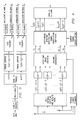
- FIG. 2 a illustrates a first preferred embodiment transmitter which encodes two symbol streams (s 1 and S 2 ) with an STTD encoder for each stream and transmits with four antennas, two antennas for each STTD encoder.
- FIG. 2 b illustrates a preferred embodiment receiver with one antenna for reception, such as for a mobile user in a cellular wireless system.
- Preferred embodiments in subsequent sections include general antenna arrangements.
- a base station may include the channel estimation and linear transformation computation as in FIG. 2 b.
- the FIG. 2 a transmitter may operate according to the FIG. 1 a flow as follows. Presume a block of data bits (with FEC) is channel encoded, block interleaved, and mapped to a block of symbols: . . . , s 1 (n), s 2 (n), s 1 (n+1), s 2 (n+1), s 1 (n+2), s 2 (n+2), s 1 (n+3), s 2 (n+3), . . . , where each symbol s j (k) is interpreted as a discrete complex number (e.g., QPSK, QAM, . . . ).
- the serial-to-parallel converter sends the stream . . .
- the upper STTD encoder has two outputs streams: . . . , x 1 (n), x 1 (n+1), x 1 (n+2), x 1 (n+3), . . . , and . . .
- x 1 (n) s 1 (n)
- x 1 (n+1) s 1 (n+1)
- x 2 (n) ⁇ s 1 *(n+1)
- x 2 (n+1) s 1 *(n). That is, the x 1 stream is just the s 1 stream and the x 2 stream is the pairwise rotation in two-complex-dimensional space of the s 1 stream.
- the lower STTD encoder has two outputs streams: . . .
- the W block linearly transforms the four streams x 1 (n), x 2 (n), x 3 (n), x 4 (n) into the four streams y 1 (n), y 2 (n), y 3 (n), y 4 (n); that is, W transforms four symbol streams into four streams of linear combinations of symbols.
- W adapts to transmission channel conditions as described below; and the choice of W enhances channel capacity. Note that the flow of FIG. 1 a presumes that the transmitter also receives signals in the same channel as its transmissions so that the transmitter can estimate the physical channel coefficients and compute W; otherwise, the transmitter must obtain W from the receiver to which it transmits.
- each of the four outputs y j (n) is next spread (multiplied by a common spreading code). Then the (spread) transformed-symbol streams drive modulators (pulse generators (at the chip rate) with essentially cosine and sine pulses for the real (in phase) and imaginary (quadrature) components of the (spread) y j (n)) which modulate the carrier wave radiated by the corresponding transmitter antennas.
- modulators pulse generators (at the chip rate) with essentially cosine and sine pulses for the real (in phase) and imaginary (quadrature) components of the (spread) y j (n)
- each sub-carrier (tone) would have its own double/multiple STTD and linear transformation.
- FIG. 2 b illustrates a first preferred embodiment receiver with one antenna which operates as indicated by FIG. 1 b .
- the antenna connects to a down-converter which drives a RAKE detector having one or more tracking fingers (including a sub-chip-rate sampler for A/D conversion, early-late chip synchronizer with despreading correlator, path channel estimation) to track resolvable received multipath signals, and the multipath detected signals may be combined using SNR weights.
- All four transmitter spreaders use the same spreading code; this increases capacity in that other spreading codes may be used for other data streams.
- Small spacing among the four transmitter antennas implies high correlation among the transmission channel coefficients in that each path from one transmitter antenna likely has corresponding highly correlated paths from the other three transmitter antennas.
- r ( n ) h 1 y 1 ( n )+ h 2 y 2 ( n )+ h 3 y 3 ( n )+ h 4 y 4 ( n )+ w ( n )
- h m is the baseband channel coefficient for the channel path(s) from the mth transmitter antenna to the receiver antenna
- w(n) is channel white noise. Note that the h m vary with n, but this variation is slow and thus ignored (except for channel estimation updates) and not explicit in the notation.
- Estimate the h m by intermittently transmitting pilot symbols from each of the four transmitter antennas; FIG. 2 b indicates channel estimation.
- a 2 is a 2 ⁇ 2 matrix corresponding to the channel path(s) of the lower pair of transmitter antennas to the receiver antenna with the first row h 3 , ⁇ h 4 and second row h 4 *, h 3 *; and w is a 2-vector with white noise components.
- the notation can be further compressed with the following definitions: 4 ⁇ 1 vector s as the vertical concatenation of s 1 and S 2 ; and 2 ⁇ 4 matrix A as the horizontal concatenation of A 1 and A 2 (thus the first row of A is [h 1 , ⁇ h 2 , h 3 , ⁇ h 4 ] and the second row is [h 2 *, h 1 *, h 4 *, h 3 *].
- r A s+w
- the matrix A is the 2 ⁇ 4 effective channel coefficient matrix of the channel from the four transmitter antennas to the receiver antenna.
- the two signals transmitted by the two transmitter antennas fed from the same STTD encoder will not interfere with each other due to the orthogonality provided by the STTD encoding.
- interference resistant detection scheme is the maximum likelihood (which is optimal) detection, linear detection (zero forcing or minimum mean square error (MMSE)), and iterative detection (zero forcing or MMSE). Both linear and iterative detectors are based on the idea of interference suppression and/or cancellation.
- a 1 H ⁇ A 1 ⁇ ( ⁇ h 1 ⁇ 2 + ⁇ h 2 ⁇ 2 ) ⁇ I 2 ⁇ ⁇ ( I 2 ⁇ ⁇ is ⁇ ⁇ 2 ⁇ 2 ⁇ ⁇ identity ⁇ ⁇ matrix )
- a 2 H ⁇ A 2 ⁇ ( ⁇ h 3 ⁇ 2 + ⁇ h 4 ⁇ 2 ) ⁇ I 2
- a 1 H ⁇ A 2 ⁇ [ ( h 1 * ⁇ h 3 + h 2 ⁇ h 4 * ) - ( h 1 * ⁇ h 4 - h 2 ⁇ h 3 * ) ( h 1 * ⁇ h 4 + h 2 ⁇ h 4 * ) * ( h 1 * ⁇ h 3 - h 2 ⁇ h 4 * ) * ( h 1 * ⁇ h 3 - h 2 ⁇ h 4 * ) * ]
- a 2 H ⁇ A 2 ⁇ ( A 1 H ⁇ A 2 ) H
- R TX transmitter spatial covariance matrix
- R RX receiver spatial covariance matrix
- ⁇ RX (1,1) is just a multiplicative constant, and the relative values of the ⁇ TX (k,m) determines the detection.
- the number of samples N used may depend upon the fading rate of the channel; but a heuristic rule of thumb takes N>5L where L is the length of vector h m .
- the estimates ⁇ m (from a pilot channel) are available from the space-time combining operation.
- the transformed physical channel in terms of x has channel coefficients :
- the 2 ⁇ 2 STTD channel matrices are ⁇ hacek over (A) ⁇ 1 with first row [ 1 , ⁇ 2 ] and second row [ 2 *, 1 *], and ⁇ hacek over (A) ⁇ 2 with first row [ 3 , ⁇ 4 ] and second row [ 4 *, 3 *];
- the channel matrix ⁇ hacek over (C) ⁇ ⁇ hacek over (A) ⁇ H ⁇ hacek over (A) ⁇ ;
- the preferred embodiments choose W so the transformed channel matrix ⁇ hacek over (C) ⁇ approximates that of an independent, identically distributed channel. This translates into finding the W that minimizes the expectation of the off-diagonal terms of ⁇ hacek over (C) ⁇ and that uniformizes the expectations of the on-diagonal terms.
- trace ⁇ W H W ⁇ 4.
- FIG. 1 b illustrates the foregoing flow, including intermittently updating the channel coefficient estimation and resultant W computation.
- FIG. 2 b shows a receiver block diagram.
- the recent channel estimates are used to generate estimates of the correlation expectations E[h k h m *] which are transformed by a W into the transformed channel correlation expectations E[ k m *] and also, by combinations, into elements of an updated E[ ⁇ hacek over (C) ⁇ ].
- update W by picking the transformation which makes E[C] approximate the maximum capacity channel with 0 off-diagonal elements and uniform on-diagonal elements. Intermittently (periodically) perform this update computation of W to adapt to changing channel conditions.
- the channel coefficients estimation could be a moving averages over a few slots (e.g., 3 slots, 6 slots, 15 slots with a 0.667 msec slot in WCDMA); or the estimation could be at the symbol rate by running the pilot through a simple smoothing filter, especially for high fading rates conditions.
- the W update may be once a transmission time interval which may be 1 slot, 3 slots, 5 slots, 15 slots. More adaptively, the updates could be according to an analysis of current channel estimates.
- the transmitter After finding W, which may be performed by both the transmitter and the receiver or just by the receiver and conveyed to the transmitter, the transmitter applies W to transmissions as illustrated in FIGS. 1 a , 2 a .
- the receiver applies W to its estimates of physical channel coefficients m from pilot transmissions to recover the transformed physical channel coefficients m and then the STTD matrices ⁇ hacek over (A) ⁇ m by expectations.
- the ⁇ hacek over (A) ⁇ m are used for space-time decoding as shown in FIGS.
- the minimization computations optimally consider all possible W and lead to complex computations.
- TDD time-division duplexing
- the W computation may be performed at the base station using its channel estimates as in FIG. 1 a ; the base station typically has available computational power.
- the W used at the transmitter can be communicated to the receiver for detection.
- the receiver itself may also compute W based on its most recent or delayed channel estimates.
- the W must be computed at the mobile receiver (the base station receives signals from the mobile in a different frequency band) and communicated to the base station via a feedback channel; consequently, quantization of W permits computations to be performed by searching (comparison-feedback) over smaller sets of possible Ws.
- a one-shot approach compares all possible choices of W and then progressively signals the quantized elements of W back to the transmitter, most significant bits first. Alternatively, partition the set of all possible W into subsets: S 1 , S 2 , . . . S K .
- the receiver compares the choices of W in a corresponding subset S k(t) , and the resulting best (minimizing) choice W (k) from this subset is then compared to the then-current previous best choices W (1) , . . . , W (K) from the other subsets, and the best W (t) of these W (1) , . . . , W (k) , . . . , W (K) is used as the update and sent to the transmitter.
- the restriction to a search of only permutation Ws reduces the computation complexity for a mobile receiver which may have limited computational power.
- the permutation matrix W may be chosen as the minimization: min ⁇ v 1
- v 1 , v 2 , and v 3 are weighting parameters that are chosen to achieve the desired degree of trade-off.
- the approach of restricting W to be a permutation can be expanded to include weighting of the nonzero elements of W.
- 2 4.
- FIG. 2 c illustrates a first preferred embodiment receiver with Q ( ⁇ 2) antennas and which, analogous to the one antenna receiver of FIG. 2 b , receives transmissions from the transmitter of FIG. 2 a ;
- FIG. 1 c is a flow diagram.
- FIG. 2 e illustrates a single antenna together with Q RAKE fingers for tracking Q resolvable received paths can effectively operate the same as Q antennas because Q resolvable paths will have differing transmission channel coefficients.
- other combinations of antennas and fingers can be interpreted as multiple antennas with single fingers or a single antenna with multiple fingers.
- r q ( n ) h q1 y 1 ( n )+ h q2 y 2 ( n )+ h q3 y 3 ( n )+ h q4 y 4 ( n )+ w q ( n )
- h qm is the baseband channel coefficient for the channel from the m th transmitter antenna to receiver antenna q
- w q (n) is channel white noise. Pilot symbols from each of the four transmitter antennas provide updating estimates for the h qm as shown in FIG. 2 d.
- FIG. 1 c is a flow diagram for the operation of the Q-antenna receiver which is analogous to and an extension of the operation of the previously-described one antenna receiver of FIG. 1 b .
- ⁇ hacek over (A) ⁇ q1 equal q1 , ⁇ q2 and second row q2 *, q1 *
- ⁇ hacek over (A) ⁇ q2 is a 2 ⁇ 2 matrix corresponding to the channels of the lower pair x 3 , x 4 to receiver antenna q with first row q3 , ⁇ q4 and second row q4 *, q3 *
- W q is a 2-vector with white noise components.
- the notation can be further compressed with the following definitions: the 2Q ⁇ 1 vector r with its first two components equal the two components of r 1 , next two components equal the two components of r 2 , and so forth to the Qth last two components equal to the two components of r Q (i.e., vertical concatenation of r 1 , r 2 , . . .
- ⁇ hacek over (A) ⁇ Q1 ⁇ hacek over (A) ⁇ Q2 (thus the first row of ⁇ hacek over (A) ⁇ is [ 11 , ⁇ h 12 , h 13 , ⁇ h 14 ] and second row [h 12 *, h 11 *, h 14 *, h 13 *], third row [h 21 , ⁇ h 22 , h 23 , ⁇ h 24 ], fourth row [h 22 *, h 21 *, h 24 *, h 23 *], and so forth down to the 2Qth row [h Q2 *, h Q1 *, h Q4 *, h Q3 *].
- r ⁇ hacek over (A) ⁇ s+w
- the matrix ⁇ hacek over (A) ⁇ is the 2Q ⁇ 4 effective transformed channel coefficient matrix of the 4Q paths: one from each of the four x m to each of the Q receiver antennas.
- the 4 ⁇ 4 transformation matrix W will be determined as previously by approximating an independent, identically distributed channel.
- 2 ) I 2 (I 2 is 2 ⁇ 2 identity matrix) ⁇ hacek over (A) ⁇ q2 H ⁇ hacek over (A) ⁇ q2 (
- ⁇ hacek over (C) ⁇ consists of sums of STTD-encoded 2 ⁇ 2 subblocks and reflects the transformed physical channel which determines performance of the communication system.
- the preferred embodiments choose the transformation W to enhance capacity of the physical channel C to yield the transformed physical channel ⁇ hacek over (C) ⁇ .
- the estimates ⁇ (from a pilot channel) are available from the space-time RAKE operation. Further, the estimates of ⁇ TX (p,p′) from various receiver antennas q can be averaged (with weightings) to improve the estimates.
- an interference resistant detector must be used to separate the two independent data streams from two STTD encoders.
- the optimal maximum likelihood detection would estimate the transmitted symbols s by ⁇ which is the vector of symbols that minimizes the sum of the errors in the received signal on the receiver antennas: ⁇ r 1 ⁇ ( ⁇ hacek over (A) ⁇ 11 ⁇ 1 + ⁇ hacek over (A) ⁇ 12 ⁇ 2 ) ⁇ 2 + ⁇ r 2 ⁇ ( ⁇ hacek over (A) ⁇ 21 ⁇ 1 + ⁇ hacek over (A) ⁇ 22 ⁇ 2 ) ⁇ + . . .
- the resulting minimum MSE for all of the 4 symbols in s corresponds to the diagonal elements of the matrix N 0 F.
- Each element of y is then passed separately to a decision device (symbol detector) to provide the corresponding hard symbol estimate.
- the iterative MMSE (IMMSE) detector is a sequence of 4 linear MMSE detection stages, where each detection provides the soft and hard symbol estimates for each of the 4 symbols in s. In each of the 4 stages, a linear MMSE transformation is performed. After the transformation, one symbol is selected for detection (based on the post detection SINR). The signal corresponding to that symbol is then regenerated and subtracted from the received signal.
- a 1 , a 2 , a 3 , and a 4 denote the first, second, third, and fourth columns of matrix ⁇ hacek over (A) ⁇ .
- v(n) denote the n-th element of a vector v.
- the following pseudo-code describes how an IMMSE detector operates:
- FIG. 2 c generalizes the foregoing transmitter from four transmit antennas to P antennas with P/2 separate STTD encoders for P/2 symbol streams s 1 , s 2 , . . . , s P/2 .
- the preceding preferred embodiments are modified so that
- r q ⁇ hacek over (A) ⁇ q1 s 1 + ⁇ hacek over (A) ⁇ q2 s 2 + . . . + ⁇ hacek over (A) ⁇ qP/2 s P/2 +W q
- r q is the 2-vector of components r q (n), r q *(n+1);
- s 1 is the 2-vector of components s 1 (n), s 1 *(n+1); . . .
- s P/2 is the 2-vector of components s P/2 (n), s P/2 *(n+1);
- ⁇ hacek over (A) ⁇ q1 is a 2 ⁇ 2 matrix corresponding to the channels of the upper pair x 1 , x 2 in FIG. 2 d to receiver antenna q with first row of ⁇ hacek over (A) ⁇ q1 equal q1 , ⁇ q2 and second row q2 *, q1 *; . . .
- ⁇ hacek over (A) ⁇ qP/2 is a 2 ⁇ 2 matrix corresponding to the channels of the bottom pair x P-1 , x P to antenna q with first row q,P-1 , ⁇ qP and second row qP *, q,P-1 *.
- the notation can be further compressed with the following definitions: the 2Q ⁇ 1 vector r with its first two components equal the two components of r 1 , next two components equal the two components of r 2 , and so forth to the Qth last two components equal to the two components of r Q (i.e., vertical concatenation of r 1 , r 2 , . . . , r Q ), P ⁇ 1 vector s as the vertical concatenation of s 1 , . . .
- ⁇ hacek over (A) ⁇ Q,P/ 2 (thus the first row of ⁇ hacek over (A) ⁇ is [ 11 , ⁇ 12 , 13 , ⁇ 14 , . . . , 1,P-1 , ⁇ 1P ] and second row [ 12 *, 11 *, 14 *, 13 *, . . . , 1P *, 1,P-1 *], third row [ 21 , ⁇ 22 , 23 , ⁇ 24 , . . . , 2,P-1 , ⁇ 2P ], fourth row [ 22 *, 21 *, 24 *, 23 *, . . . .
- the matrix A is the 2Q ⁇ P effective transformed channel coefficient matrix of the PQ paths: one from each of the P transmitter antennas to each of the Q receiver antennas.
- the P ⁇ P transformation matrix W will be determined as previously by approximating an independent, identically distributed channel.
- a ⁇ qm H ⁇ A ⁇ qm ( ⁇ ⁇ q , 2 ⁇ m - 1 ⁇ 2 + ⁇ ⁇ q , 2 ⁇ m ⁇ 2 ) ⁇ I 2 ( I 2 ⁇ ⁇ is ⁇ ⁇ 2 ⁇ 2 ⁇ ⁇ identity ⁇ ⁇ matrix )
- a ⁇ qk H ⁇ A ⁇ qm [ ( ⁇ q , 2 ⁇ k - 1 * ⁇ ⁇ q , 2 ⁇ m - 1 + ⁇ q , 2 ⁇ k ⁇ ⁇ q , 2 ⁇ m * ) - ( ⁇ q , 2 ⁇ k - 1 * ⁇ ⁇ q , 2 ⁇ m - ⁇ q , 2 ⁇ k ⁇ ⁇ q , 2 ⁇ m - 1 * ) ( ⁇ q , 2 ⁇ k - 1 * ⁇ ⁇ q , 2 ⁇
- the channel is frequency selective (contains multiple propagation paths with different delays)
- two possible scenarios can occur.
- the first scenario is relevant to CDMA systems with large spreading gain (e.g. ⁇ 128) and the channel delay spread is small compared to one symbol duration.
- different paths arriving at the receiver at different delays can be resolved to provide multipath diversity without causing significant amount of inter-symbol interference.
- Additional path diversity can be treated as having additional receive antennas (e.g. having 2-path diversity at each antenna is equivalent to having 2Q receive antennas).
- the second scenario is relevant to higher data rate systems where the channel delay spread is sufficiently large compared to one symbol duration that the effect of inter-symbol interference is significant.
- multipath interference suppression can be used in conjunction to the spatial interference resistant detector, especially when the number of users/codes is large and/or higher order modulation is used.
- the concept described above for selecting the best linear transformation W can be extended to this scenario.
- the above description applies to systems that employ multiple STTD encoding.
- the aforementioned weighting technique for combating the effect of correlated channels can also be applied to multi-input multi-output (MIMO) systems that do not employ any space-time coding.
- MIMO multi-input multi-output
- P and Q the number of transmit and receive antennas
- the received (despread) baseband signal across all receive antennas at any time interval can be written in a Q-dimensional vector as:
- h p denotes the Q-vector channel corresponding to the p-th transmit antenna
- x p is the transmitted signal via the p-th transmit antenna.
- the matrix H is the Q ⁇ P MIMO channel matrix and the vector x is the P ⁇ 1 transmitted signal vector. Note that in this case, the time index (n) can be suppressed since the transmitted symbols are independent across time.
- the P ⁇ 1 transmitted signal vector x is obtained from the linearly transformed P ⁇ 1 transmitted data symbol vector s.
- H contains the actual physical channel coefficients. That is, the (q,p)-th element of matrix H corresponds to the channel between the p-th transmit antenna and q-th receive antenna.
- the rule for choosing W is similar to that for multiple STTD systems described above: choose W so that the corresponding transformed E[H H H], denoted E[M], will resemble the channel matrix of an independent, identically distributed channel in that: (1) expectations of off-diagonal elements are close to 0 and (2) expectations of on-diagonal elements are uniform.
- the off-diagonal elements reflect the average additional interference due to channel correlations, and the smallest on-diagonal element corresponds to the stream with the worst signal to interference plus noise ratio (SINR), which dominates performance.
- the minimization computations optimally consider all possible W and lead to complex computations.
- TDD time-division duplexing
- the W computation may be performed at the base station using its channel estimates as in FIG. 1 a ; the base station typically has available computational power.
- the W used at the transmitter can be communicated to the receiver for detection.
- the receiver itself may also compute W based on its most recent or delayed channel estimates.
- the W must be computed at the mobile receiver (the base station receives signals from the mobile in a different frequency band) and communicated to the base station via a feedback channel; consequently, quantization of W permits computations to be performed by searching (comparison-feedback) over smaller sets of possible Ws.
- a one-shot approach compares all possible choices of W and then progressively signals the quantized elements of W back to the transmitter, most significant bits first. Alternatively, partition the set of all possible W into subsets: S 1 , S 2 , . . . S K .
- the receiver compares the choices of W in a corresponding subset S k(t) , and the resulting best (minimizing) choice W (k) from this subset is then compared to the then-current previous best choices W (1) , . . . , W (K) from the other subsets, and the best W (t) of these W (1) , . . . , W (k) , . . . W (K) is used as the update and sent to the transmitter.
- FIG. 3 illustrates asymmetric modulation preferred embodiments for two symbol streams (analogous to FIG. 2 a ) in which the symbol mapping differs for the streams;
- FIG. 1 d is a flow diagram.
- the serial-to-parallel converter processes 6 bits per symbol interval by alternating sets of 2 bits to the upper symbol mapper and 4 bits to the lower symbol mapper.
- the upper symbol mapper maps a set of 2 bits into a QPSK symbol
- the lower mapper maps a set of 4 bits into a 16-QAM symbol.
- the resulting symbol streams (upper QPSK and lower 16-QAM) are each STTD encoded (and spread) and transmitted.
- the serial-to-parallel converter could process groups of 12 bits (2 symbol intervals) by 4 bits to the upper mapper for two QPSK symbols followed by 8 bits to the lower mapper for two 16-QAM symbols.
- This asymmetric symbol constellation sizes can take advantage of asymmetries in the channel (space diversity).
- the symbol mapping may be adaptive to the channel by using channel estimates to compare capacity of the transmitter antennas.
- the symbol mappers may provide multiple symbol constellations for dynamic adaptation; or all the symbol mappings may be performed in a single (programmable) DSP or other processor.
- FIG. 4 shows a receiver for the asymmetric symbol transmission where detection uses the appropriate symbol constellations which are updated intermittently (periodically).
- the asymmetric symbol preferred embodiments can also use time diversity in that the symbol mapping may alternate in successive symbol periods. And time diversity can be mixed with space diversity. In particular, for 12 bits per 2 symbol intervals the following symbol possibilities arise:
- different combinations of 4 modulation (symbol mapping) schemes can be used, one for each transmit antenna.
- different combinations of P modulation schemes can be used.
- a combination of P modulation schemes corresponds to a particular assignment of P modulation schemes to P different symbols.
- a fixed criterion does not depend on the channel dynamics, whereas an adaptive criterion periodically updates the modulation assignment based upon the change in channel condition.
- Adaptive criterion can be based on several metrics.
- One possible metric is to minimize the bit error rate (BER) or the frame error rate (FER) for a given channel realization while fixing the data rate.
- the set of possible modulation assignments contains different assignments, which result in the same data rate.
- Another possible metric is to maximize the system throughput (data rate) for a given channel realization while imposing a worst-case error rate (BER or FER) constraint.
- the set of modulation assignments contains different assignments with varying data rates.
- a relation/mapping between the channel parameters and the error rate (BER or FER) is needed. Such mapping depends on the type of detector that is used at the receiver.
- a union bound for BER in terms of the channel parameters and modulation assignment scheme can be derived.
- the selected assignment for the first case should be the one that results in the minimum BER bound.
- the error rate is a decreasing function of minimum/worst-case post-detection SINR, where the minimum is taken across all the P symbols.
- the selected assignment for the first case should be the one that results in the largest minimum/worst-case post-detection SINR. Closed-form expressions of the post-detection SINR for each symbol can be derived for different types of linear and iterative detectors.
- h qp is the physical channel coefficient from transmit antenna p to receive antenna q.
- r q A q1 s 1 +A q2 s 2 + . . . +A qP/2 s P/2 +w q
- r q is the 2-vector of components r q (n), r q *(n+1)
- a q1 is a 2 ⁇ 2 matrix corresponding to the channels of the upper pair x 1 , x 2 in FIG.
- the notation can be further compressed with the following definitions: the 2Q ⁇ 1 vector r with its first two components equal the two components of r 1 , next two components equal the two components of r 2 , and so forth to the Qth last two components equal to the two components of r Q (i.e., vertical concatenation of r 1 , r 2 , . . . , r Q ), P ⁇ 1 vector s as the vertical concatenation of s 1 . . . s P/2 ; and 2Q ⁇ P matrix A as the Q ⁇ P/2 array of 2 ⁇ 2 matrices A 11 A 12 . . . A 1,P/2 ; A 21 A 22 , . . .
- the resulting minimum MSE for all the 4 symbols in s corresponds to the diagonal elements of the matrix N 0 F.
- Each element of y is then passed separately to a decision device (symbol detector) provide the corresponding hard symbol estimate.
- the iterative MMSE (IMMSE) detector is a sequence of 4 linear MMSE detection stages, where each detection provides the soft and hard symbol estimates for each of the 4 symbols in s. In each of the 4 stages, a linear MMSE transformation is performed. After the transformation, one symbol is selected for detection. The signal corresponding to that symbol is then regenerated and subtracted from the received signal.
- IMMSE iterative MMSE
- SINR ( n ) ( E nn /N 0 ) F nn ⁇ 1 where F nn indicates the n-th diagonal element of matrix F.
- matrix F is the same for all the symbols in s (see the above discussion on LMMSE).
- matrix F is different for different symbols in s since each symbol is detected at different iteration.
- This SINR expression can be used for selecting the symbol to be detected at each iteration. Based on the above relation, the selected symbol is the one that results in the minimum (F nn /E nn ). Symbol selection at each iteration can also be thought of as finding the detection order.
- the SINR expression given above is instrumental for selecting the modulation assignment (described above) as it provides an explicit relation between the post-detection SINR (which is inversely related to BER or FER) and the channel condition (conveyed in matrix F) for both linear and iterative MMSE detectors.
- the adaptive assignment selection chooses a modulation assignment that maximizes the worst-case SINR (minimum SINR across all the symbols in s).
- the system throughput is maximized by selecting an assignment with the highest possible data rate that still satisfies the error rate constraint. In this case, the mapping between SINR and error rate can be used.
- the symbol mapping asymmetry also extends to the case of more than 2 streams with STTD encoding; that is, the transmitter of FIG. 2 c can have an asymmetric symbol mapping among the P/2 streams.
- the asymmetric modulation preferred embodiments can also follow the setup of FIG. 2 a in that the symbol mapping may be performed prior to the serial-to-parallel. Further, the STTD encoder outputs of the asymmetric symbols can also be linearly transformed prior to transmission; thereby combining the asymmetry with the channel adaptation of preceding preferred embodiments. In fact, a permutation linear transformation together with fixed symbol mappers can provide the choice among space-only, time-only, and space-time asymmetries.
- the receiver with Q antennas may be as in FIG. 2 d with the detection including searches over asymmetric constellation products.
- both the transmitter and the receiver can compute channel conditions and thus the constellation selection, but either the transmitter or the receiver alone could perform the computations and convey to the other the constellation selection.
- the receiver assesses the channel conditions and conveys information to the transmitter; and the transmitter could perform the selection computation and convey such to the receiver.
- channels A and B are flat Rayleigh fading models (peak cross-correlation of 0.6 for channel B).
- 1234 denotes regular double STTD without permutation; 3124 is the optimal permutation for channel A; and 1432 is the optimal permutation for channel B.
- the optimal permutation does not depend upon the modulation scheme, it only depends upon the spatial covariance profile.
- FIGS. 8-9 show comparisons of both STTD encoding 8-PSK with one STTD encoding QPSK and the other 16-QAM (i.e., spatial asymmetry) for an ID channel and for channel B, respectively.
- ModeDetect means the modified iterative detector in which instead of using the post-detection symbol SINR, use the MSE scaled by the average symbol energy.
- the preferred embodiments can be modified in various ways while retaining the features of linear transformation of symbols prior to transmission and/or symmetrical symbol mapping.
- the receiver could have the linear transformation provided by the transmitter and thereby avoid the computation; the STTD could be 3 ⁇ 3 or larger; the asymmetric symbol encoding could also apply to general multiple input, multiple output (MIMO) systems; . . .
Abstract
Description
r(n)=h 1 y 1(n)+h 2 y 2(n)+h 3 y 3(n)+h 4 y 4(n)+w(n)
where hm is the baseband channel coefficient for the channel path(s) from the mth transmitter antenna to the receiver antenna and w(n) is channel white noise. Note that the hm vary with n, but this variation is slow and thus ignored (except for channel estimation updates) and not explicit in the notation. Estimate the hm by intermittently transmitting pilot symbols from each of the four transmitter antennas;
and so
This can be expressed in terms of 2-vectors and 2×2 matrices as:
r=A 1 s 1 +A 2 s 2 +w
where r is the 2-vector of components r(n), r*(n+1); s1 is the 2-vector of components s1(n), s1*(n+1); s2 is the 2-vector of components s2(n), S2*(n+1); A1 is a 2×2 matrix corresponding to the channel path(s) of the upper pair of transmitter antennas in
r=A s+w
The matrix A is the 2×4 effective channel coefficient matrix of the channel from the four transmitter antennas to the receiver antenna.
min ∥r−Aŝ∥ 2=min ∥r−(A 1 ŝ 1 +A 2 ŝ 2)∥2
Because there are a finite number of symbols in a constellation (e.g., QAM, QPSK, . . . ), there are only a finite number of symbol pairs to search for the minimization. And the minimization computations can use the channel estimates  (derived from received known pilot symbol transmissions) in place of A. Further, the detector output may be a soft (log of symbol probability) output for each possible symbol; a MAP decoder would use such detector outputs.
z=A H r=A H(A s+w)=C s+A H w
Then the decoding minimization formally becomes
min(z−Cŝ)HC−1(z−Cŝ)
where C is the 4×4 Hermitian matrix AH A which can be viewed as a 2×2 array of 2×2 matrices Ak HAm for k,m=1, 2 with
That is, C consists of STTD-encoded 2×2 subblocks and reflects the physical channel which determines performance of the communication system.
Rk,m=E[hkhm*]
For fading channels with rich scatterers (typical conditions for cellular wireless), the scattering at the transmitter and at the receiver are independent; and this independence, in general, implies R decomposes as the tensor product of the transmitter spatial covariance matrix RTX (elements ρTX(k,m)) and the receiver spatial covariance matrix RRX (elements ρRX(i,j)). That is, R=RRX
E[hkhm*]=ρRX(1,1)ρTX(k,m) for k,m=1, 2, 3, 4
Thus ρRX(1,1) is just a multiplicative constant, and the relative values of the ρTX(k,m) determines the detection.
ρRX(1,1)ρTX(k,m)=(1/N)Σ1≦n≦N ĥ k [n]ĥ m *[n]
where N is the number of samples and the ĥm[n] are the channel coefficient estimates for symbol interval n. The number of samples N used may depend upon the fading rate of the channel; but a heuristic rule of thumb takes N>5L where L is the length of vector hm. The estimates ĥm (from a pilot channel) are available from the space-time combining operation.
Take h to be the 4-vector with components h1, h2, h3, h4 and
Likewise in terms of x, the 2×2 STTD channel matrices are {hacek over (A)}1 with first row [
min{|E[
min{|E[|
Thus the overall detection approach in
min({hacek over (A)}Hr−{hacek over (C)}ŝ)H{hacek over (C)}−1({hacek over (A)}Hr−{hacek over (C)}ŝ)
where. {hacek over (C)} is roughly the identity matrix. In this case, one may approximate the maximum likelihood matrix as
min ∥{hacek over (A)}Hr−{hacek over (C)}ŝ∥2
min{v1|E[hπ(1)*hπ(3)+hπ(2)hπ(4)*]|2+v2|E[hπ(1)*hπ(4)−hπ(2)h π(3)*]|2+v3|E[|hπ(1)|2+|hπ(2)|2]−2|2}
where v1, v2, and v3 are weighting parameters that are chosen to achieve the desired degree of trade-off.
r q(n)=h q1 y 1(n)+h q2y2(n)+h q3 y 3(n)+h q4 y 4(n)+w q(n)
where hqm is the baseband channel coefficient for the channel from the mth transmitter antenna to receiver antenna q and wq(n) is channel white noise. Pilot symbols from each of the four transmitter antennas provide updating estimates for the hqm as shown in
or more explicitly,
and
This can again be expressed in terms of 2-vectors and 2×2 matrices as:
r q ={hacek over (A)} q1 s 1 +{hacek over (A)} q2 s 2 +w q
where rq is the 2-vector of components rq(n), rq*(n+1); s1 is the 2-vector of components s1(n), s1*(n+1); s2 is the 2-vector of components s2(n), s2*(n+1); {hacek over (A)}q1 is a 2×2 matrix corresponding to the channels of the upper pair x1, x2 in
r={hacek over (A)}s+w
The matrix {hacek over (A)} is the 2Q×4 effective transformed channel coefficient matrix of the 4Q paths: one from each of the four xm to each of the Q receiver antennas. The 4×4 transformation matrix W will be determined as previously by approximating an independent, identically distributed channel.
{hacek over (A)} q1 H {hacek over (A)} q1=(|h q1|2 +|h q2| 2)I 2 (I2 is 2×2 identity matrix)
{hacek over (A)} q2 H {hacek over (A)} q2=(|h q3|2 +|h q4|2)I 2
{hacek over (A)}q2 H{hacek over (A)}q1=({hacek over (A)}q1 H{hacek over (A)}q2)H
ρRX(q,q)ρTX(p,p′)=(1/N)Σ1≦n≦N ĥ qp [n]ĥ qp′ *[n]
where N is the number of samples in the average. The estimates ĥ (from a pilot channel) are available from the space-time RAKE operation. Further, the estimates of ρTX(p,p′) from various receiver antennas q can be averaged (with weightings) to improve the estimates.
min{|Σ1≦q≦QE[
min{|Σ1≦q≦QE[|
with a normalization of Σ1≦q≦Q E[|
∥r1−({hacek over (A)}11ŝ1+{hacek over (A)}12ŝ2)∥2+∥r2−({hacek over (A)}21ŝ1+{hacek over (A)}22ŝ2)∥+ . . . +∥rQ−({hacek over (A)}Q1ŝ1+{hacek over (A)}Q2ŝ2)∥2
Such a maximum likelihood detection becomes computationally intensive with larger antenna systems. Since the size of matrix {hacek over (A)} is 2Q×4, linear (1-shot) and iterative detectors with lower complexity are applicable when Q is at least 2. As mentioned before, both linear and iterative detectors are based on the idea of interference suppression/cancellation. Possible methods include zero forcing and minimum mean square error (MMSE). In the following, the linear MMSE (LMMSE) and iterative MMSE (IMMSE) detectors are explained. A zero-forcing-based detector can be obtained from its MMSE analog by removing the second term in the matrix inverse.
z={hacek over (A)} H r={hacek over (A)} H({hacek over (A)}s+w)={hacek over (C)}s+{hacek over (A)}w
the LMMSE detector essentially performs a linear transformation F to the statistics z such that the mean square error (MSE) E[∥F z−s∥2] is minimized. The (theoretically derived) linear transformation F is:
F=({hacek over (C)}+N 0 /E s I 4)−1
where N0 is the energy of each of the 2Q components of the white noise w, Es is the average energy of each symbol in s (assume that all the symbols in s are of the same constellation, modulation scheme), and I4 is the 4×4 identity matrix. As noted above, the linear transformation for linear zero-forcing (LZF) detector is simply
F=({hacek over (C)})−1
And the resulting minimum MSE for all of the 4 symbols in s corresponds to the diagonal elements of the matrix N0F. The resulting linearly transformed statistics y=Fz is essentially the soft estimate of s. Each element of y is then passed separately to a decision device (symbol detector) to provide the corresponding hard symbol estimate.
| B = [ a1 a2 a3 a4 ] | ||
| for p=1 to 4 | ||
| F = ( BH B + N0/Es I)− : (4−p+1) × (4−p+1) matrix | |
| y = F BH r : (4−p+1) ×1 vector | |
| Find the smallest diagonal element of matrix F | |
| Select one out of (4−p+1) symbols to be detected which |
| corresponds to the smallest diagonal element of | |
| matrix F: let that be s(o(p) ) |
| Obtain soft estimate of symbol s(o(p) ) from the |
| corresponding element of y |
| Find the hard estimate of s(o(p) ): σ(o(p) ) | |
| r = r − ao(p) σ (o(p) ) | |
| Remove column ao(p) from B |
| end | ||
Note that the symbol selection is based on the diagonal elements of matrix F, which correspond to symbol MSEs. Theoretically, the symbol MSE is inversely proportional to SINR.
4. Multiple Antenna Preferred Embodiments
and similarly
where W is a P×P linear transformation of P-vector x to P-vector y=W*x as in
r q ={hacek over (A)} q1 s 1 +{hacek over (A)} q2 s 2 + . . . +{hacek over (A)} qP/2 s P/2 +W q
where rq is the 2-vector of components rq(n), rq*(n+1); s1 is the 2-vector of components s1(n), s1*(n+1); . . . , sP/2 is the 2-vector of components sP/2(n), sP/2*(n+1); {hacek over (A)}q1 is a 2×2 matrix corresponding to the channels of the upper pair x1, x2 in
r={hacek over (A)}s+w
The matrix A is the 2Q×P effective transformed channel coefficient matrix of the PQ paths: one from each of the P transmitter antennas to each of the Q receiver antennas. The P×P transformation matrix W will be determined as previously by approximating an independent, identically distributed channel.
That is, {hacek over (C)} consists of sums of STTD-encoded 2×2 subblocks and reflects the transformed physical channel and determines performance of the communication system. Again, the preferred embodiments choose the transformation W to enhance capacity of the physical channel C to yield the transformed physical channel {hacek over (C)}.
E[hqphq′p′*]=ρRX(q,q′)ρTX(p,p′) for p,p′=1, . . . , P; q,q′=1, . . . , Q
Then for each pair q,q′, all of the ρTX(p,p′) can be found up to the multiplicative constant ρRX(q,q′). That is, the separability of the receiver covariance and transmitter covariance means that the previously-analyzed case Q=1 suffices. Indeed, the transformation W in general leads to the transmitter covariance {hacek over (R)}TX=WH RTX W and the covariance {hacek over (R)}=(IQ
ρRX(q,q)ρTX(p,p′)=(1/N)Σ1≦n≦N ĥ qp [n]ĥ qp′ *[n]
where N is the number of samples in the average. The estimates ĥ (from a pilot channel) are available from the space-time RAKE operation.
with a normalization of E[|
where hp denotes the Q-vector channel corresponding to the p-th transmit antenna, and xp is the transmitted signal via the p-th transmit antenna. The matrix H is the Q×P MIMO channel matrix and the vector x is the P×1 transmitted signal vector. Note that in this case, the time index (n) can be suppressed since the transmitted symbols are independent across time.
r=H W s+w
Unlike in multiple STTD encoded systems, H contains the actual physical channel coefficients. That is, the (q,p)-th element of matrix H corresponds to the channel between the p-th transmit antenna and q-th receive antenna.
E[hqphq′p′*]=ρRX(q,q′)ρTX(p,p′) for p,p′=1, . . . , P; q,q′=1, . . . , Q
Then for each pair q,q′, all of the ρTX(p,p′) can be found up to the multiplicative constant ρRX(q,q′). That is, the separability of the receiver covariance and transmitter covariance means that the previously-analyzed case Q=1 suffices.
M=WHHHH W
where the (i,j)-th element of matrix HHH is hi Hhj=Σ1≦q≦Q hiq*hqj. Hence, the elements of matrix E[HH H] can be directly related to the elements of matrix R since Σ1≦q≦Q E[hiq*hqj]=Σ1≦q≦QρRX(i,q) ρTX(q,j).
min{Σ1≦i≦PΣi≦j≦P|Mij|}
min{Σ1≦i≦P|Mij−1 |}
with a normalization of Σ1≦i≦P M11=P and trace{WHW}=P.
For FDD systems, the angles θ and φ can be uniformly quantized to finite number of values. For systems with P>2, Givens or Householder rotations can be used.
7. Asymmetric Modulation Preferred Embodiments
| asymmetry | s1(n) | s1(n + 1) | s2(n) | s2(n + 1) | ||
| none | 8PSK | 8PSK | 8PSK | 8PSK | ||
| space | QPSK | QPSK | 16-QAM | 16-QAM | ||
| time | QPSK | 16-QAM | QPSK | 16-QAM | ||
| space/time | QPSK | 16-QAM | 16-QAM | QPSK | ||
For other numbers of bits per symbol interval, other symbol constellations would be used; for example, 18 bits per 2 symbol intervals could use 16-QAM plus 32-QAM. And the bit rate (bits per symbol interval) could vary in time, so the pairs of constellations used would also vary.
and similarly
where hqp is the physical channel coefficient from transmit antenna p to receive antenna q.
r q =A q1 s 1 +A q2 s 2 + . . . +A qP/2 s P/2 +w q
where rq is the 2-vector of components rq(n), rq*(n+1); S1 is the 2-vector of components s1(n), s1*(n+1); . . . , sP/2 is the 2-vector of components sP/2(n), sP/2*(n+1); Aq1 is a 2×2 matrix corresponding to the channels of the upper pair x1, x2 in
r=A s+w
The matrix A is the 2Q×P effective transformed channel coefficient matrix of the PQ paths: one from each of the P transmitter antennas to each of the Q receiver antennas.
z=A H r=A H(A s+w)=C s+A H w
the LMMSE detector essentially performs a linear transformation F to the statistics z such that the mean square error (MSE) E[∥F z−s∥2] is minimized. Again, theoretically, such linear transformation F is:
F=(C+N 0 E −1)−1
where N0 is the energy of each of the 2Q components of the white noise w, E is the 4×4 diagonal matrix of symbol average energies: E11 is average energy of s1(n), E22 average of s1(n+1), E33 average of s2(n), E44 average of s2(n+1) (e.g., n denotes even-indexed symbol intervals and n+1 denotes odd-indexed intervals). As noted above, the linear transformation for linear zero-forcing (LZF) detector is simply F=C−1.
| B = [ a1 a2 a3 a4 ] | ||
| E = diag{ E11 , E22 , E33 , E44 } | ||
| for p=1 to 4 | ||
| F = ( BH B + N0 E−1 )−1 : (4−p+1) × (4−p+1) matrix | |
| y = F BH r : (4−p+1) ×1 vector | |
| Find the smallest diagonal element of matrix F | |
| Select one out of (4−p+1) symbols to be detected which |
| corresponds to largest SINR: let that be s(o(p) ) |
| Obtain soft estimate of symbol s(o(p) ) from the |
| corresponding element of y |
| Find the hard estimate of s(o(p) ): σ(o(p) ) | |
| r = r − ao(p) σ (o(p) ) | |
| Remove column ao(p) from B | |
| Remove column o(p) and row o(p) from matrix E |
| end | ||
The extension for systems with P=2p (p≧3) transmit antennas is straightforward.
SINR(n)=(E nn /N 0)F nn−1
where Fnn indicates the n-th diagonal element of matrix F. For LMMSE, matrix F is the same for all the symbols in s (see the above discussion on LMMSE). For IMMSE, matrix F is different for different symbols in s since each symbol is detected at different iteration. This SINR expression can be used for selecting the symbol to be detected at each iteration. Based on the above relation, the selected symbol is the one that results in the minimum (Fnn/Enn). Symbol selection at each iteration can also be thought of as finding the detection order.
Claims (16)
Priority Applications (1)
| Application Number | Priority Date | Filing Date | Title |
|---|---|---|---|
| US10/144,114 US7801247B2 (en) | 2001-05-01 | 2002-05-13 | Multiple input, multiple output system and method |
Applications Claiming Priority (5)
| Application Number | Priority Date | Filing Date | Title |
|---|---|---|---|
| US28799801P | 2001-05-01 | 2001-05-01 | |
| US28820901P | 2001-05-02 | 2001-05-02 | |
| US10/135,611 US7778355B2 (en) | 2001-05-01 | 2002-04-30 | Space-time transmit diversity |
| US10/135,679 US7133459B2 (en) | 2001-05-01 | 2002-04-30 | Space-time transmit diversity |
| US10/144,114 US7801247B2 (en) | 2001-05-01 | 2002-05-13 | Multiple input, multiple output system and method |
Related Parent Applications (1)
| Application Number | Title | Priority Date | Filing Date |
|---|---|---|---|
| US10/135,611 Continuation-In-Part US7778355B2 (en) | 2001-05-01 | 2002-04-30 | Space-time transmit diversity |
Publications (2)
| Publication Number | Publication Date |
|---|---|
| US20030210750A1 US20030210750A1 (en) | 2003-11-13 |
| US7801247B2 true US7801247B2 (en) | 2010-09-21 |
Family
ID=29400252
Family Applications (1)
| Application Number | Title | Priority Date | Filing Date |
|---|---|---|---|
| US10/144,114 Expired - Lifetime US7801247B2 (en) | 2001-05-01 | 2002-05-13 | Multiple input, multiple output system and method |
Country Status (1)
| Country | Link |
|---|---|
| US (1) | US7801247B2 (en) |
Cited By (23)
| Publication number | Priority date | Publication date | Assignee | Title |
|---|---|---|---|---|
| US20080095262A1 (en) * | 2004-08-03 | 2008-04-24 | Agency For Science, Technology And Research | Method for Transmitting a Digital Data Stream, Transmitter, Method for Receiving a Digital Data Stream and Receiver |
| US20080232238A1 (en) * | 2001-06-10 | 2008-09-25 | Agee Brian G | Method and system for robust, secure, and high-efficiency voice and packet transmission over ad-hoc, mesh, and MIMO communication networks |
| US20120069887A1 (en) * | 2009-06-19 | 2012-03-22 | Sungho Park | Method of Minimizing Feedback Overhead Using Spatial Channel Covariance in a Multi-Input Multi-Output System |
| US20140029680A1 (en) * | 2012-07-26 | 2014-01-30 | The Boeing Company | System and Method for Generating an On-Demand Modulation Waveform for Use in Communications between Radios |
| US9312895B1 (en) | 2008-08-07 | 2016-04-12 | Hypres, Inc. | Two stage radio frequency interference cancellation system and method |
| US9628231B2 (en) | 2002-05-14 | 2017-04-18 | Genghiscomm Holdings, LLC | Spreading and precoding in OFDM |
| US9660764B2 (en) * | 2007-07-04 | 2017-05-23 | Lg Electronics Inc. | Broadcast transmitter and method of processing broadcast service data for transmission |
| US9768842B2 (en) | 2002-05-14 | 2017-09-19 | Genghiscomm Holdings, LLC | Pre-coding in multi-user MIMO |
| US10142082B1 (en) | 2002-05-14 | 2018-11-27 | Genghiscomm Holdings, LLC | Pre-coding in OFDM |
| US10200227B2 (en) | 2002-05-14 | 2019-02-05 | Genghiscomm Holdings, LLC | Pre-coding in multi-user MIMO |
| US10305636B1 (en) | 2004-08-02 | 2019-05-28 | Genghiscomm Holdings, LLC | Cooperative MIMO |
| US10644916B1 (en) | 2002-05-14 | 2020-05-05 | Genghiscomm Holdings, LLC | Spreading and precoding in OFDM |
| US10797733B1 (en) | 2001-04-26 | 2020-10-06 | Genghiscomm Holdings, LLC | Distributed antenna systems |
| US10880145B2 (en) | 2019-01-25 | 2020-12-29 | Genghiscomm Holdings, LLC | Orthogonal multiple access and non-orthogonal multiple access |
| US10931338B2 (en) | 2001-04-26 | 2021-02-23 | Genghiscomm Holdings, LLC | Coordinated multipoint systems |
| US11018918B1 (en) | 2017-05-25 | 2021-05-25 | Genghiscomm Holdings, LLC | Peak-to-average-power reduction for OFDM multiple access |
| US11115160B2 (en) | 2019-05-26 | 2021-09-07 | Genghiscomm Holdings, LLC | Non-orthogonal multiple access |
| US11184037B1 (en) | 2004-08-02 | 2021-11-23 | Genghiscomm Holdings, LLC | Demodulating and decoding carrier interferometry signals |
| US11196603B2 (en) | 2017-06-30 | 2021-12-07 | Genghiscomm Holdings, LLC | Efficient synthesis and analysis of OFDM and MIMO-OFDM signals |
| US11343823B2 (en) | 2020-08-16 | 2022-05-24 | Tybalt, Llc | Orthogonal multiple access and non-orthogonal multiple access |
| US11381285B1 (en) | 2004-08-02 | 2022-07-05 | Genghiscomm Holdings, LLC | Transmit pre-coding |
| US11552737B1 (en) | 2004-08-02 | 2023-01-10 | Genghiscomm Holdings, LLC | Cooperative MIMO |
| US11917604B2 (en) | 2019-01-25 | 2024-02-27 | Tybalt, Llc | Orthogonal multiple access and non-orthogonal multiple access |
Families Citing this family (48)
| Publication number | Priority date | Publication date | Assignee | Title |
|---|---|---|---|---|
| US7092737B2 (en) * | 2002-07-31 | 2006-08-15 | Mitsubishi Electric Research Laboratories, Inc. | MIMO systems with rate feedback and space time transmit diversity |
| US7263132B2 (en) * | 2002-08-13 | 2007-08-28 | Mitsubishi Electric Research Laboratories, Inc. | Adaptive space-time transmit diversity coding for MIMO systems |
| KR100511299B1 (en) * | 2002-12-13 | 2005-08-31 | 엘지전자 주식회사 | Data symbol mapping and spreading apparatus for mobile communication system |
| FR2848747A1 (en) * | 2002-12-16 | 2004-06-18 | France Telecom | Pre-coded signal emitting process for wireless communication system, involves interlacing pre-coded transmitted symbols to modify temporal order of symbols and coding each block of symbols according to coding time space |
| US7130580B2 (en) * | 2003-03-20 | 2006-10-31 | Lucent Technologies Inc. | Method of compensating for correlation between multiple antennas |
| US7197082B2 (en) * | 2003-03-20 | 2007-03-27 | Lucent Technologies Inc. | Linear transformation of symbols to at least partially compensate for correlation between antennas in space time block coded systems |
| US8064528B2 (en) | 2003-05-21 | 2011-11-22 | Regents Of The University Of Minnesota | Estimating frequency-offsets and multi-antenna channels in MIMO OFDM systems |
| US7340015B1 (en) * | 2003-08-18 | 2008-03-04 | Qualcomm Incorporated | Asymmetric wireless protocol communications wherein upstream traffic uses one protocol and downstream traffic uses a different protocol |
| US7643438B2 (en) * | 2003-08-28 | 2010-01-05 | Alcatel-Lucent Usa Inc. | Method of determining random access channel preamble detection performance in a communication system |
| US7724838B2 (en) * | 2003-09-25 | 2010-05-25 | Qualcomm Incorporated | Hierarchical coding with multiple antennas in a wireless communication system |
| US7006840B2 (en) * | 2003-09-30 | 2006-02-28 | Interdigital Technology Corporation | Efficient frame tracking in mobile receivers |
| DE60313001T2 (en) * | 2003-12-10 | 2007-08-30 | Motorola, Inc., Schamburg | Space / time transit diversity method and device |
| KR100789355B1 (en) * | 2004-03-05 | 2008-01-02 | 가부시키가이샤 엔티티 도코모 | Receiver apparatus, receiving method, and wireless communication system |
| US8422585B2 (en) | 2004-04-01 | 2013-04-16 | Research In Motion Limited | Space-time block coding systems and methods |
| EP1730869B1 (en) * | 2004-04-01 | 2009-11-18 | Nortel Networks Limited | Space-time block coding system and methods |
| US7636406B2 (en) * | 2004-05-05 | 2009-12-22 | Metalink Ltd. | System and method of a MIMO transmitter / receiver |
| US20050281361A1 (en) * | 2004-06-16 | 2005-12-22 | Broadcom Corporation | Interference cancellation of STBC with multiple streams in OFDM for wlan |
| EP1615366A1 (en) * | 2004-07-08 | 2006-01-11 | Motorola, Inc. | Method and apparatus for transmitting and receiving a datasymbol stream |
| US7606319B2 (en) * | 2004-07-15 | 2009-10-20 | Nokia Corporation | Method and detector for a novel channel quality indicator for space-time encoded MIMO spread spectrum systems in frequency selective channels |
| US7362822B2 (en) * | 2004-09-08 | 2008-04-22 | Intel Corporation | Recursive reduction of channel state feedback |
| US7492829B2 (en) * | 2004-09-10 | 2009-02-17 | Intel Corporation | Closed loop feedback in MIMO systems |
| US7539253B2 (en) | 2004-09-10 | 2009-05-26 | Intel Corporation | Interpolation in channel state feedback |
| US7236748B2 (en) * | 2004-09-30 | 2007-06-26 | Intel Corporation | Closed loop feedback in MIMO systems |
| US7609780B2 (en) * | 2004-09-30 | 2009-10-27 | Intel Corporation | Method and apparatus for performing sequential closed loop multiple input multiple output (MIMO) |
| US7778826B2 (en) * | 2005-01-13 | 2010-08-17 | Intel Corporation | Beamforming codebook generation system and associated methods |
| JPWO2006129750A1 (en) * | 2005-06-03 | 2009-01-08 | 松下電器産業株式会社 | Radio transmission apparatus, radio reception apparatus, and signal arrangement method |
| JP4695212B2 (en) * | 2006-12-11 | 2011-06-08 | テレフオンアクチーボラゲット エル エム エリクソン(パブル) | Antenna system monitoring method |
| US7764747B2 (en) | 2007-03-30 | 2010-07-27 | Olympus Corporation | Methods and systems for transmitting and processing pilot signals |
| US7843990B2 (en) * | 2007-04-09 | 2010-11-30 | Alcatel-Lucent Usa Inc. | Determining a channel matrix by measuring interference |
| US8830812B2 (en) | 2007-08-31 | 2014-09-09 | Alcatel Lucent | Optimizing precoder settings using average SINR reports for groups of tones |
| US8155063B2 (en) * | 2008-04-28 | 2012-04-10 | Apple Inc. | Apparatus and methods for transmission and reception of data in multi-antenna systems |
| US8217802B2 (en) * | 2009-02-03 | 2012-07-10 | Schlumberger Technology Corporation | Methods and systems for borehole telemetry |
| US8362916B2 (en) * | 2009-02-05 | 2013-01-29 | Schlumberger Technology Corporation | Methods and systems for borehole telemetry |
| US8295335B2 (en) * | 2009-12-31 | 2012-10-23 | Intel Corporation | Techniques to control uplink power |
| WO2012089241A1 (en) * | 2010-12-28 | 2012-07-05 | Telefonaktiebolaget L M Ericsson (Publ) | Improved wireless communication system |
| WO2012119269A1 (en) * | 2011-03-10 | 2012-09-13 | Telefonaktiebolaget L M Ericsson (Publ) | Apparatus and method for detecting faulty antennas |
| US9722841B1 (en) * | 2014-07-16 | 2017-08-01 | University Of South Florida | Channel-based coding for wireless communications |
| US10020839B2 (en) | 2016-11-14 | 2018-07-10 | Rampart Communications, LLC | Reliable orthogonal spreading codes in wireless communications |
| US10873361B2 (en) | 2019-05-17 | 2020-12-22 | Rampart Communications, Inc. | Communication system and methods using multiple-in-multiple-out (MIMO) antennas within unitary braid divisional multiplexing (UBDM) |
| US11641269B2 (en) | 2020-06-30 | 2023-05-02 | Rampart Communications, Inc. | Modulation-agnostic transformations using unitary braid divisional multiplexing (UBDM) |
| US11050604B2 (en) | 2019-07-01 | 2021-06-29 | Rampart Communications, Inc. | Systems, methods and apparatuses for modulation-agnostic unitary braid division multiplexing signal transformation |
| US10917148B2 (en) | 2019-07-01 | 2021-02-09 | Rampart Communications, Inc. | Systems, methods and apparatus for secure and efficient wireless communication of signals using a generalized approach within unitary braid division multiplexing |
| US11025470B2 (en) * | 2019-07-01 | 2021-06-01 | Rampart Communications, Inc. | Communication system and method using orthogonal frequency division multiplexing (OFDM) with non-linear transformation |
| US10833749B1 (en) * | 2019-07-01 | 2020-11-10 | Rampart Communications, Inc. | Communication system and method using layered construction of arbitrary unitary matrices |
| US10951442B2 (en) | 2019-07-31 | 2021-03-16 | Rampart Communications, Inc. | Communication system and method using unitary braid divisional multiplexing (UBDM) with physical layer security |
| US10735062B1 (en) | 2019-09-04 | 2020-08-04 | Rampart Communications, Inc. | Communication system and method for achieving high data rates using modified nearly-equiangular tight frame (NETF) matrices |
| US10965352B1 (en) | 2019-09-24 | 2021-03-30 | Rampart Communications, Inc. | Communication system and methods using very large multiple-in multiple-out (MIMO) antenna systems with extremely large class of fast unitary transformations |
| US11159220B2 (en) | 2020-02-11 | 2021-10-26 | Rampart Communications, Inc. | Single input single output (SISO) physical layer key exchange |
Citations (19)
| Publication number | Priority date | Publication date | Assignee | Title |
|---|---|---|---|---|
| US6047020A (en) * | 1996-03-19 | 2000-04-04 | Nokia Telecommunications Oy | Receiving method and a receiver |
| US6058105A (en) * | 1997-09-26 | 2000-05-02 | Lucent Technologies Inc. | Multiple antenna communication system and method thereof |
| US6112095A (en) * | 1997-01-08 | 2000-08-29 | Us Wireless Corporation | Signature matching for location determination in wireless communication systems |
| US6128330A (en) * | 1998-11-24 | 2000-10-03 | Linex Technology, Inc. | Efficient shadow reduction antenna system for spread spectrum |
| US6131016A (en) * | 1997-08-27 | 2000-10-10 | At&T Corp | Method and apparatus for enhancing communication reception at a wireless communication terminal |
| US6178196B1 (en) * | 1997-10-06 | 2001-01-23 | At&T Corp. | Combined interference cancellation and maximum likelihood decoding of space-time block codes |
| US20010033622A1 (en) * | 2000-03-14 | 2001-10-25 | Joengren George | Robust utilization of feedback information in space-time coding |
| US6317411B1 (en) * | 1999-02-22 | 2001-11-13 | Motorola, Inc. | Method and system for transmitting and receiving signals transmitted from an antenna array with transmit diversity techniques |
| US6327303B1 (en) * | 1998-07-30 | 2001-12-04 | Motorola, Inc. | Method and system for data transmission using a lossy compression service |
| US20010053143A1 (en) * | 2000-05-22 | 2001-12-20 | Ye Li | MIMO OFDM system |
| US6351499B1 (en) * | 1999-12-15 | 2002-02-26 | Iospan Wireless, Inc. | Method and wireless systems using multiple antennas and adaptive control for maximizing a communication parameter |
| US20020172293A1 (en) * | 2001-03-28 | 2002-11-21 | Kiran Kuchi | Non-zero complex weighted space-time code for multiple antenna transmission |
| US6510173B1 (en) * | 1998-10-08 | 2003-01-21 | Centro De Technologia Vidriera Monterrey, S.A. | Method for the orthogonal and offset transmission-reception of a signal and device for realizing the same |
| US6542556B1 (en) * | 2000-03-31 | 2003-04-01 | Nokia Mobile Phones Ltd. | Space-time code for multiple antenna transmission |
| US6643333B1 (en) * | 1997-03-26 | 2003-11-04 | Siemens Aktiengesellschaft | Method and transmitting device for transmitting data symbols from subscriber signals via a radio interface of a mobile communications system |
| US6721300B1 (en) * | 2000-03-22 | 2004-04-13 | Matsushita Electric Industrial Co., Ltd | STTD encoding method and diversity transmitter |
| US6850481B2 (en) * | 2000-09-01 | 2005-02-01 | Nortel Networks Limited | Channels estimation for multiple input—multiple output, orthogonal frequency division multiplexing (OFDM) system |
| US6891897B1 (en) * | 1999-07-23 | 2005-05-10 | Nortel Networks Limited | Space-time coding and channel estimation scheme, arrangement and method |
| US6898248B1 (en) * | 1999-07-12 | 2005-05-24 | Hughes Electronics Corporation | System employing threaded space-time architecture for transporting symbols and receivers for multi-user detection and decoding of symbols |
-
2002
- 2002-05-13 US US10/144,114 patent/US7801247B2/en not_active Expired - Lifetime
Patent Citations (20)
| Publication number | Priority date | Publication date | Assignee | Title |
|---|---|---|---|---|
| US6047020A (en) * | 1996-03-19 | 2000-04-04 | Nokia Telecommunications Oy | Receiving method and a receiver |
| US6112095A (en) * | 1997-01-08 | 2000-08-29 | Us Wireless Corporation | Signature matching for location determination in wireless communication systems |
| US6643333B1 (en) * | 1997-03-26 | 2003-11-04 | Siemens Aktiengesellschaft | Method and transmitting device for transmitting data symbols from subscriber signals via a radio interface of a mobile communications system |
| US6131016A (en) * | 1997-08-27 | 2000-10-10 | At&T Corp | Method and apparatus for enhancing communication reception at a wireless communication terminal |
| US6058105A (en) * | 1997-09-26 | 2000-05-02 | Lucent Technologies Inc. | Multiple antenna communication system and method thereof |
| US6178196B1 (en) * | 1997-10-06 | 2001-01-23 | At&T Corp. | Combined interference cancellation and maximum likelihood decoding of space-time block codes |
| US6327303B1 (en) * | 1998-07-30 | 2001-12-04 | Motorola, Inc. | Method and system for data transmission using a lossy compression service |
| US6510173B1 (en) * | 1998-10-08 | 2003-01-21 | Centro De Technologia Vidriera Monterrey, S.A. | Method for the orthogonal and offset transmission-reception of a signal and device for realizing the same |
| US6757322B2 (en) * | 1998-11-24 | 2004-06-29 | Linex Technologies, Inc. | Space diversity and coding, spread-spectrum antenna and method |
| US6128330A (en) * | 1998-11-24 | 2000-10-03 | Linex Technology, Inc. | Efficient shadow reduction antenna system for spread spectrum |
| US6317411B1 (en) * | 1999-02-22 | 2001-11-13 | Motorola, Inc. | Method and system for transmitting and receiving signals transmitted from an antenna array with transmit diversity techniques |
| US6898248B1 (en) * | 1999-07-12 | 2005-05-24 | Hughes Electronics Corporation | System employing threaded space-time architecture for transporting symbols and receivers for multi-user detection and decoding of symbols |
| US6891897B1 (en) * | 1999-07-23 | 2005-05-10 | Nortel Networks Limited | Space-time coding and channel estimation scheme, arrangement and method |
| US6351499B1 (en) * | 1999-12-15 | 2002-02-26 | Iospan Wireless, Inc. | Method and wireless systems using multiple antennas and adaptive control for maximizing a communication parameter |
| US20010033622A1 (en) * | 2000-03-14 | 2001-10-25 | Joengren George | Robust utilization of feedback information in space-time coding |
| US6721300B1 (en) * | 2000-03-22 | 2004-04-13 | Matsushita Electric Industrial Co., Ltd | STTD encoding method and diversity transmitter |
| US6542556B1 (en) * | 2000-03-31 | 2003-04-01 | Nokia Mobile Phones Ltd. | Space-time code for multiple antenna transmission |
| US20010053143A1 (en) * | 2000-05-22 | 2001-12-20 | Ye Li | MIMO OFDM system |
| US6850481B2 (en) * | 2000-09-01 | 2005-02-01 | Nortel Networks Limited | Channels estimation for multiple input—multiple output, orthogonal frequency division multiplexing (OFDM) system |
| US20020172293A1 (en) * | 2001-03-28 | 2002-11-21 | Kiran Kuchi | Non-zero complex weighted space-time code for multiple antenna transmission |
Non-Patent Citations (1)
| Title |
|---|
| Liang et al "Downlink Channel Covariance Matrix (DCCM) Estimation and its Applications in Wireless DS-CDMA Systems", IEEE Journal on Selected Area in Communications, vol. 19, No. 2, Feb. 2001,pp. 222-232. * |
Cited By (80)
| Publication number | Priority date | Publication date | Assignee | Title |
|---|---|---|---|---|
| US9106286B2 (en) | 2000-06-13 | 2015-08-11 | Comcast Cable Communications, Llc | Network communication using diversity |
| US9344233B2 (en) | 2000-06-13 | 2016-05-17 | Comcast Cable Communications, Llc | Originator and recipient based transmissions in wireless communications |
| USRE45775E1 (en) | 2000-06-13 | 2015-10-20 | Comcast Cable Communications, Llc | Method and system for robust, secure, and high-efficiency voice and packet transmission over ad-hoc, mesh, and MIMO communication networks |
| USRE45807E1 (en) | 2000-06-13 | 2015-11-17 | Comcast Cable Communications, Llc | Apparatus for transmitting a signal including transmit data to a multiple-input capable node |
| US9722842B2 (en) | 2000-06-13 | 2017-08-01 | Comcast Cable Communications, Llc | Transmission of data using a plurality of radio frequency channels |
| US8315326B2 (en) | 2000-06-13 | 2012-11-20 | Aloft Media, Llc | Apparatus for generating at least one signal based on at least one aspect of at least two received signals |
| US8315327B2 (en) | 2000-06-13 | 2012-11-20 | Aloft Media, Llc | Apparatus for transmitting a signal including transmit data to a multiple-input capable node |
| US9820209B1 (en) | 2000-06-13 | 2017-11-14 | Comcast Cable Communications, Llc | Data routing for OFDM transmissions |
| US8451928B2 (en) | 2000-06-13 | 2013-05-28 | Aloft Media, Llc | Apparatus for calculating weights associated with a first signal and applying the weights to a second signal |
| US8451929B2 (en) | 2000-06-13 | 2013-05-28 | Aloft Media, Llc | Apparatus for calculating weights associated with a received signal and applying the weights to transmit data |
| US9515788B2 (en) | 2000-06-13 | 2016-12-06 | Comcast Cable Communications, Llc | Originator and recipient based transmissions in wireless communications |
| US9401783B1 (en) | 2000-06-13 | 2016-07-26 | Comcast Cable Communications, Llc | Transmission of data to multiple nodes |
| US9654323B2 (en) | 2000-06-13 | 2017-05-16 | Comcast Cable Communications, Llc | Data routing for OFDM transmission based on observed node capacities |
| US20110142108A1 (en) * | 2000-06-13 | 2011-06-16 | Cpu Consultants, Inc. | Apparatus for Calculating Weights Associated with a First Signal and Applying the Weights to a Second Signal |
| US9391745B2 (en) | 2000-06-13 | 2016-07-12 | Comcast Cable Communications, Llc | Multi-user transmissions |
| US9197297B2 (en) | 2000-06-13 | 2015-11-24 | Comcast Cable Communications, Llc | Network communication using diversity |
| US9209871B2 (en) | 2000-06-13 | 2015-12-08 | Comcast Cable Communications, Llc | Network communication using diversity |
| US10349332B2 (en) | 2000-06-13 | 2019-07-09 | Comcast Cable Communications, Llc | Network communication using selected resources |
| US10257765B2 (en) | 2000-06-13 | 2019-04-09 | Comcast Cable Communications, Llc | Transmission of OFDM symbols |
| US9356666B1 (en) | 2000-06-13 | 2016-05-31 | Comcast Cable Communications, Llc | Originator and recipient based transmissions in wireless communications |
| US11424792B2 (en) | 2001-04-26 | 2022-08-23 | Genghiscomm Holdings, LLC | Coordinated multipoint systems |
| US10797733B1 (en) | 2001-04-26 | 2020-10-06 | Genghiscomm Holdings, LLC | Distributed antenna systems |
| US10797732B1 (en) | 2001-04-26 | 2020-10-06 | Genghiscomm Holdings, LLC | Distributed antenna systems |
| US10931338B2 (en) | 2001-04-26 | 2021-02-23 | Genghiscomm Holdings, LLC | Coordinated multipoint systems |
| US20080232238A1 (en) * | 2001-06-10 | 2008-09-25 | Agee Brian G | Method and system for robust, secure, and high-efficiency voice and packet transmission over ad-hoc, mesh, and MIMO communication networks |
| US8363744B2 (en) | 2001-06-10 | 2013-01-29 | Aloft Media, Llc | Method and system for robust, secure, and high-efficiency voice and packet transmission over ad-hoc, mesh, and MIMO communication networks |
| US10230559B1 (en) | 2002-05-14 | 2019-03-12 | Genghiscomm Holdings, LLC | Spreading and precoding in OFDM |
| US10389568B1 (en) | 2002-05-14 | 2019-08-20 | Genghiscomm Holdings, LLC | Single carrier frequency division multiple access baseband signal generation |
| US9768842B2 (en) | 2002-05-14 | 2017-09-19 | Genghiscomm Holdings, LLC | Pre-coding in multi-user MIMO |
| US9800448B1 (en) | 2002-05-14 | 2017-10-24 | Genghiscomm Holdings, LLC | Spreading and precoding in OFDM |
| US9628231B2 (en) | 2002-05-14 | 2017-04-18 | Genghiscomm Holdings, LLC | Spreading and precoding in OFDM |
| US11025468B1 (en) | 2002-05-14 | 2021-06-01 | Genghiscomm Holdings, LLC | Single carrier frequency division multiple access baseband signal generation |
| US9967007B2 (en) | 2002-05-14 | 2018-05-08 | Genghiscomm Holdings, LLC | Cooperative wireless networks |
| US10009208B1 (en) | 2002-05-14 | 2018-06-26 | Genghiscomm Holdings, LLC | Spreading and precoding in OFDM |
| US10015034B1 (en) | 2002-05-14 | 2018-07-03 | Genghiscomm Holdings, LLC | Spreading and precoding in OFDM |
| US10038584B1 (en) | 2002-05-14 | 2018-07-31 | Genghiscomm Holdings, LLC | Spreading and precoding in OFDM |
| US10142082B1 (en) | 2002-05-14 | 2018-11-27 | Genghiscomm Holdings, LLC | Pre-coding in OFDM |
| US10200227B2 (en) | 2002-05-14 | 2019-02-05 | Genghiscomm Holdings, LLC | Pre-coding in multi-user MIMO |
| US10211892B2 (en) | 2002-05-14 | 2019-02-19 | Genghiscomm Holdings, LLC | Spread-OFDM receiver |
| US11025312B2 (en) | 2002-05-14 | 2021-06-01 | Genghiscomm Holdings, LLC | Blind-adaptive decoding of radio signals |
| US10903970B1 (en) | 2002-05-14 | 2021-01-26 | Genghiscomm Holdings, LLC | Pre-coding in OFDM |
| US10840978B2 (en) | 2002-05-14 | 2020-11-17 | Genghiscomm Holdings, LLC | Cooperative wireless networks |
| US10778492B1 (en) | 2002-05-14 | 2020-09-15 | Genghiscomm Holdings, LLC | Single carrier frequency division multiple access baseband signal generation |
| US10644916B1 (en) | 2002-05-14 | 2020-05-05 | Genghiscomm Holdings, LLC | Spreading and precoding in OFDM |
| US10574497B1 (en) | 2002-05-14 | 2020-02-25 | Genghiscomm Holdings, LLC | Spreading and precoding in OFDM |
| US10587369B1 (en) | 2002-05-14 | 2020-03-10 | Genghiscomm Holdings, LLC | Cooperative subspace multiplexing |
| US11671299B1 (en) | 2004-08-02 | 2023-06-06 | Genghiscomm Holdings, LLC | Wireless communications using flexible channel bandwidth |
| US11018917B1 (en) | 2004-08-02 | 2021-05-25 | Genghiscomm Holdings, LLC | Spreading and precoding in OFDM |
| US11575555B2 (en) | 2004-08-02 | 2023-02-07 | Genghiscomm Holdings, LLC | Carrier interferometry transmitter |
| US11552737B1 (en) | 2004-08-02 | 2023-01-10 | Genghiscomm Holdings, LLC | Cooperative MIMO |
| US10305636B1 (en) | 2004-08-02 | 2019-05-28 | Genghiscomm Holdings, LLC | Cooperative MIMO |
| US11431386B1 (en) | 2004-08-02 | 2022-08-30 | Genghiscomm Holdings, LLC | Transmit pre-coding |
| US11646929B1 (en) | 2004-08-02 | 2023-05-09 | Genghiscomm Holdings, LLC | Spreading and precoding in OFDM |
| US11381285B1 (en) | 2004-08-02 | 2022-07-05 | Genghiscomm Holdings, LLC | Transmit pre-coding |
| US11223508B1 (en) | 2004-08-02 | 2022-01-11 | Genghiscomm Holdings, LLC | Wireless communications using flexible channel bandwidth |
| US11252005B1 (en) | 2004-08-02 | 2022-02-15 | Genghiscomm Holdings, LLC | Spreading and precoding in OFDM |
| US11784686B2 (en) | 2004-08-02 | 2023-10-10 | Genghiscomm Holdings, LLC | Carrier interferometry transmitter |
| US11804882B1 (en) | 2004-08-02 | 2023-10-31 | Genghiscomm Holdings, LLC | Single carrier frequency division multiple access baseband signal generation |
| US11075786B1 (en) | 2004-08-02 | 2021-07-27 | Genghiscomm Holdings, LLC | Multicarrier sub-layer for direct sequence channel and multiple-access coding |
| US11252006B1 (en) | 2004-08-02 | 2022-02-15 | Genghiscomm Holdings, LLC | Wireless communications using flexible channel bandwidth |
| US11184037B1 (en) | 2004-08-02 | 2021-11-23 | Genghiscomm Holdings, LLC | Demodulating and decoding carrier interferometry signals |
| US20080095262A1 (en) * | 2004-08-03 | 2008-04-24 | Agency For Science, Technology And Research | Method for Transmitting a Digital Data Stream, Transmitter, Method for Receiving a Digital Data Stream and Receiver |
| US7986743B2 (en) * | 2004-08-03 | 2011-07-26 | Agency For Science, Technology And Research | Method for transmitting a digital data stream, transmitter, method for receiving a digital data stream and receiver |
| US9660764B2 (en) * | 2007-07-04 | 2017-05-23 | Lg Electronics Inc. | Broadcast transmitter and method of processing broadcast service data for transmission |
| US9838051B1 (en) | 2008-08-07 | 2017-12-05 | Hypres, Inc. | Two stage radio frequency interference cancellation system and method |
| US9312895B1 (en) | 2008-08-07 | 2016-04-12 | Hypres, Inc. | Two stage radio frequency interference cancellation system and method |
| US20120069887A1 (en) * | 2009-06-19 | 2012-03-22 | Sungho Park | Method of Minimizing Feedback Overhead Using Spatial Channel Covariance in a Multi-Input Multi-Output System |
| US8503516B2 (en) * | 2009-06-19 | 2013-08-06 | Lg Electronics Inc. | Method of minimizing feedback overhead using spatial channel covariance in a multi-input multi-output system |
| US20140029680A1 (en) * | 2012-07-26 | 2014-01-30 | The Boeing Company | System and Method for Generating an On-Demand Modulation Waveform for Use in Communications between Radios |
| US9325545B2 (en) * | 2012-07-26 | 2016-04-26 | The Boeing Company | System and method for generating an on-demand modulation waveform for use in communications between radios |
| US11700162B2 (en) | 2017-05-25 | 2023-07-11 | Tybalt, Llc | Peak-to-average-power reduction for OFDM multiple access |
| US11018918B1 (en) | 2017-05-25 | 2021-05-25 | Genghiscomm Holdings, LLC | Peak-to-average-power reduction for OFDM multiple access |
| US11894965B2 (en) | 2017-05-25 | 2024-02-06 | Tybalt, Llc | Efficient synthesis and analysis of OFDM and MIMO-OFDM signals |
| US11570029B2 (en) | 2017-06-30 | 2023-01-31 | Tybalt Llc | Efficient synthesis and analysis of OFDM and MIMO-OFDM signals |
| US11196603B2 (en) | 2017-06-30 | 2021-12-07 | Genghiscomm Holdings, LLC | Efficient synthesis and analysis of OFDM and MIMO-OFDM signals |
| US10880145B2 (en) | 2019-01-25 | 2020-12-29 | Genghiscomm Holdings, LLC | Orthogonal multiple access and non-orthogonal multiple access |
| US11917604B2 (en) | 2019-01-25 | 2024-02-27 | Tybalt, Llc | Orthogonal multiple access and non-orthogonal multiple access |
| US11791953B2 (en) | 2019-05-26 | 2023-10-17 | Tybalt, Llc | Non-orthogonal multiple access |
| US11115160B2 (en) | 2019-05-26 | 2021-09-07 | Genghiscomm Holdings, LLC | Non-orthogonal multiple access |
| US11343823B2 (en) | 2020-08-16 | 2022-05-24 | Tybalt, Llc | Orthogonal multiple access and non-orthogonal multiple access |
Also Published As
| Publication number | Publication date |
|---|---|
| US20030210750A1 (en) | 2003-11-13 |
Similar Documents
| Publication | Publication Date | Title |
|---|---|---|
| US7801247B2 (en) | Multiple input, multiple output system and method | |
| US7133459B2 (en) | Space-time transmit diversity | |
| US7778355B2 (en) | Space-time transmit diversity | |
| US7181167B2 (en) | High data rate closed loop MIMO scheme combining transmit diversity and data multiplexing | |
| US10128920B2 (en) | Multi-antenna transmission for spatial division multiple access | |
| US8018903B2 (en) | Closed-loop transmit diversity scheme in frequency selective multipath channels | |
| US8290098B2 (en) | Closed loop multiple transmit, multiple receive antenna wireless communication system | |
| KR100948007B1 (en) | Wireless transmission using an adaptive transmit antenna array | |
| CN1823487B (en) | Method and controller for controlling communication resources | |
| US9923617B2 (en) | Communication channel optimization systems and methods in multi-user communication systems | |
| US7929631B2 (en) | Multiple space time transmit diversity communication system with selected complex conjugate inputs | |
| US7894538B2 (en) | Frequency-independent spatial processing for wideband MISO and MIMO systems | |
| Derryberry et al. | Transmit diversity in 3G CDMA systems | |
| US7301893B2 (en) | Linear space-time block code with block STTD structure | |
| Blostein et al. | Multiple antenna systems: their role and impact in future wireless access | |
| US7020175B2 (en) | MMSE reception of DS-CDMA with transmit diversity | |
| JP2004533787A (en) | Wireless communication system | |
| US20040218697A1 (en) | Array processing using an aggregate channel matrix generated using a block code structure | |
| Mietzner et al. | Boosting the performance of wireless communication systems: theory and practice of multiple-antenna techniques | |
| JP4567749B2 (en) | Method and apparatus for performing chip level equalization using combined processing | |
| Li et al. | Performance comparisons of MIMO techniques with application to WCDMA systems |
Legal Events
| Date | Code | Title | Description |
|---|---|---|---|
| AS | Assignment |
Owner name: TEXAS INSTRUMENTS INCORPORATED, TEXAS Free format text: ASSIGNMENT OF ASSIGNORS INTEREST;ASSIGNORS:ONGGOSANUSI, EKO N.;DABAK, ANAND G.;REEL/FRAME:013217/0397 Effective date: 20020805 |
|
| STCF | Information on status: patent grant |
Free format text: PATENTED CASE |
|
| FPAY | Fee payment |
Year of fee payment: 4 |
|
| MAFP | Maintenance fee payment |
Free format text: PAYMENT OF MAINTENANCE FEE, 8TH YEAR, LARGE ENTITY (ORIGINAL EVENT CODE: M1552) Year of fee payment: 8 |
|
| MAFP | Maintenance fee payment |
Free format text: PAYMENT OF MAINTENANCE FEE, 12TH YEAR, LARGE ENTITY (ORIGINAL EVENT CODE: M1553); ENTITY STATUS OF PATENT OWNER: LARGE ENTITY Year of fee payment: 12 |