US8104479B2 - Pleated bag for interventional pullback systems - Google Patents
Pleated bag for interventional pullback systems Download PDFInfo
- Publication number
- US8104479B2 US8104479B2 US11/453,441 US45344106A US8104479B2 US 8104479 B2 US8104479 B2 US 8104479B2 US 45344106 A US45344106 A US 45344106A US 8104479 B2 US8104479 B2 US 8104479B2
- Authority
- US
- United States
- Prior art keywords
- bag
- catheter
- folds
- pullback
- motor drive
- Prior art date
- Legal status (The legal status is an assumption and is not a legal conclusion. Google has not performed a legal analysis and makes no representation as to the accuracy of the status listed.)
- Expired - Fee Related, expires
Links
Images


Classifications
-
- A—HUMAN NECESSITIES
- A61—MEDICAL OR VETERINARY SCIENCE; HYGIENE
- A61B—DIAGNOSIS; SURGERY; IDENTIFICATION
- A61B8/00—Diagnosis using ultrasonic, sonic or infrasonic waves
- A61B8/44—Constructional features of the ultrasonic, sonic or infrasonic diagnostic device
- A61B8/4483—Constructional features of the ultrasonic, sonic or infrasonic diagnostic device characterised by features of the ultrasound transducer
- A61B8/4488—Constructional features of the ultrasonic, sonic or infrasonic diagnostic device characterised by features of the ultrasound transducer the transducer being a phased array
-
- A—HUMAN NECESSITIES
- A61—MEDICAL OR VETERINARY SCIENCE; HYGIENE
- A61B—DIAGNOSIS; SURGERY; IDENTIFICATION
- A61B8/00—Diagnosis using ultrasonic, sonic or infrasonic waves
- A61B8/12—Diagnosis using ultrasonic, sonic or infrasonic waves in body cavities or body tracts, e.g. by using catheters
-
- A—HUMAN NECESSITIES
- A61—MEDICAL OR VETERINARY SCIENCE; HYGIENE
- A61B—DIAGNOSIS; SURGERY; IDENTIFICATION
- A61B46/00—Surgical drapes
- A61B46/10—Surgical drapes specially adapted for instruments, e.g. microscopes
-
- A—HUMAN NECESSITIES
- A61—MEDICAL OR VETERINARY SCIENCE; HYGIENE
- A61B—DIAGNOSIS; SURGERY; IDENTIFICATION
- A61B8/00—Diagnosis using ultrasonic, sonic or infrasonic waves
- A61B8/44—Constructional features of the ultrasonic, sonic or infrasonic diagnostic device
- A61B8/4422—Constructional features of the ultrasonic, sonic or infrasonic diagnostic device related to hygiene or sterilisation
-
- A—HUMAN NECESSITIES
- A61—MEDICAL OR VETERINARY SCIENCE; HYGIENE
- A61B—DIAGNOSIS; SURGERY; IDENTIFICATION
- A61B8/00—Diagnosis using ultrasonic, sonic or infrasonic waves
- A61B8/44—Constructional features of the ultrasonic, sonic or infrasonic diagnostic device
- A61B8/4444—Constructional features of the ultrasonic, sonic or infrasonic diagnostic device related to the probe
- A61B8/4461—Features of the scanning mechanism, e.g. for moving the transducer within the housing of the probe
Definitions
- catheters used in interventional medicine are sterile, single-use products, which are disposed after the procedure.
- Catheters are inserted intraluminally, including intravascular and non-intravascular placement. Catheters can also be inserted interstitially.
- Many catheters used for diagnosis or treatment are designed to be used over a range of axial insertion depths.
- the distal end of the catheter contains a diagnostic or therapeutic element that needs to be placed in the desired target area.
- the target area in the body is longer than the diagnostic or therapeutic element, and so the catheter needs to be moved along the target area, so that the entire area can be either diagnosed or treated.
- IVUS intravascular ultrasound
- a catheter with one or more ultrasonic transducers at its tip is gradually pulled back along the length of a blood vessel or vascular structure in order to produce an ultrasonic image of the vessel and its disease.
- catheters are pulled or pushed by means of pullback devices. These devices are usually attached to the proximal end of the catheter that extends out of the patient.
- the devices have a motor that serves to move the catheter at a steady rate in the desired longitudinal direction. This in turn moves the distal element of the catheter through the desired range in the target area.
- the pullback devices have motors and other relatively expensive mechanical and electrical components, they are often constructed and supplied as non-sterile, reusable devices. These devices usually need to be close to the patient, so it is often desirable to place them on the sterile field, for example, on top of the patient's legs or between the patient's legs.
- IVUS pullback devices have consisted of two main parts, a motor drive and a sled. These parts are separable from each other, and are attached together prior to use.
- the motor drive has a separate motor for rotating a drive shaft containing an ultrasonic transducer at the tip.
- the sled has its own longitudinal drive motor.
- this device known commercially as the Boston Scientific ClearView pullback device, two sterile bags are used, one to cover the motor drive and one to cover the sled. After attaching the two covered parts to each other, the entire assembly can be placed on the sterile field.
- the bag that covers the sled is forced to bunch up, due the translation between the carriage of the sled and the base of the sled. For this reason, the user must manually create slack in the sled bag prior to fully attaching the catheter and beginning a pullback.
- 6,398,755 consists of a reusable motor drive and a disposable sterile sled.
- a single bag is placed over the motor drive and the sterile sled is attached to the motor drive by piercing the bag at the interface point. Because the carriage of the sled and the base of the sled are sterile, and do not need to be covered with a bag, there is no bunching up for the user to be concerned with. However, the user must now purchase not only the sterile bag but also a sterile sled for each procedure, increasing the cost per patient. In all of these devices, because the motor drive is separate from the sled, and thus needs to be attached, the motor drive is sometimes handled by itself, during which it is possible to drop and damage it.
- the device presented in U.S. Pat. No. 5,797,858 also allows for a single sterile bag.
- the required gearing for the longitudinal drive is a part of the sterile disposable catheter assembly, instead of being a part of the pullback device.
- the pullback device is covered with a single bag and the catheter is snapped in place. There is no bunching of the bag required.
- Another improvement with this device is that it does not have a separate motor drive and sled that need to be attached to each other.
- the only attachment step is the attachment of the catheter to the pullback device.
- the additional parts in the catheter increase its cost to manufacture.
- a single sterile bag that can enclose both the carriage for the motor drive and the sled of a catheter pullback device and expand as the carriage is translated along the sled.
- This invention relates to a pullback device, catheter and sterile bag design that overcomes many of the drawbacks of the previous designs.
- the catheter requires no extra parts and there is only one sterile bag required, so the cost per patient is a minimum.
- the pullback device does not consist of a separate motor drive and sled that must be attached to each other. It is a single component device that need only be covered by a bag.
- the bag has built in pleats that allow for the longitudinal displacement of the moving portion of the pullback device in relation to the stationary portion, without requiring that the user bunch up the material.
- the bag also has an orifice through which the proximal connector of the catheter is slid, allowing the catheter to be connected directly to the motor drive, without risk of contamination.
- a simple partial turn of the catheter connector into the pullback device locks it in place.
- the catheter is configured with a rigid inner sheath to minimize the chance of kinking during use with the pullback device.
- the catheter also has a reinforced guidewire lumen to avoid tearing of the lumen by the guidewire.
- FIG. 1 illustrates a pullback device
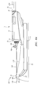
- FIG. 2 illustrates a sterile bag with pleats and an orifice.
- FIG. 3 illustrates an IVUS catheter for use with the sterile bag and pullback device.
- FIG. 4 is a detailed view of the distal end of the same IVUS catheter.
- FIG. 4 a is an orthogonal view of the same distal end, showing the drive shaft/transducer assembly inside.
- FIG. 5 is a detailed view of the proximal end of the same IVUS catheter.
- FIG. 5 a is a detailed view of the catheter connector of the same IVUS catheter.
- FIG. 6 is side view of the IVUS catheter attached to the pullback device and covered by the sterile bag, with a longitudinal section shown down the centerline of sterile bag.
- FIG. 6 a is the same combined view as FIG. 6 , but with the pullback device and catheter in fully retracted positions.
- FIG. 7 illustrates the pullback device after initial placement in the sterile bag.
- FIG. 8 illustrates the pullback device inside the sterile bag, with the motor drive of the pullback device retracted and the ring of the sterile bag inserted into the motor drive, the preferred configuration for catheter attachment.
- FIG. 9 illustrates the IVUS catheter being inserted into the motor drive of the pullback device through the orifice in the sterile bag.
- FIG. 10 illustrates the IVUS catheter being locked onto the pullback device.
- FIG. 11 illustrates the IVUS catheter in its locked state.
- FIG. 12 illustrates the outer sheath of the IVUS catheter being attached to the outer sheath clip of the pullback device.
- FIG. 13 illustrates a close-up of the sheath hub of the outer sheath of the IVUS catheter secured to the outer sheath clip of the pullback device.
- FIG. 14 illustrates the IVUS catheter, pullback device and sterile bag in the attached and fully retracted configuration, ready for catheter priming.
- FIG. 15 illustrates the catheter priming step.
- FIG. 16 illustrates the fully advanced configuration, after catheter priming and prior to the start of catheter pullback.
- FIG. 17 illustrates the IVUS catheter/pullback device/sterile bag system after approximately 5 cm of pullback.
- FIG. 18 illustrates the IVUS catheter/pullback device/sterile bag system after approximately 8 cm of pullback.
- FIG. 19 illustrates the IVUS catheter/pullback device/sterile bag system after approximately 13 cm of pullback.
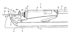
- FIG. 1 shows a unitary pullback device 5 for moving an ultrasonic transducer 175 of an IVUS catheter 120 in the axial direction inside a blood vessel.
- the pullback device 5 consists of a motor drive 10 and a sled 15 .
- the motor drive 10 and the sled 15 are permanently attached to each other, allowing the pullback device 5 to be handled, carried, stored and used without need to attach or detach the motor drive 10 and sled 15 , and without the possibility of misplacing or damaging the motor drive 10 .
- the pullback device 5 has two portions to which the IVUS catheter 120 is attached; they are a catheter interface 20 and an outer sheath clip 25 .
- the motor drive includes a rotational motor (not shown), which serves to rotate the drive shaft 165 of the IVUS catheter 120 .
- Power is delivered to the pullback device via a cable (not shown) that is attached to a cable input 30 on the motor drive 10 .
- information is transferred to and from the pullback device via the same cable.
- the motor drive 10 is moved longitudinally along the sled 15 over rod 40 and rack/rod 35 .
- the motor drive 10 can be driven on rack/rod 35 by a pinion gear (not shown).
- a sterile bag 75 is represented that serves to cover the pullback device 5 in order to maintain sterility during a sterile procedure.
- the sterile bag 75 includes a proximal end 80 having extendable folds that can be unfolded to cover the cable.
- the distal end 85 of the sterile bag 75 may include a clipping target area 100 for clipping the catheter to the outer sheath clip 25 .
- a ring 90 having an orifice 95 may be located along the centerline of the sterile bag 75 and may be sized to allow passage of the very proximal end of the IVUS catheter 120 .
- a pleated section 105 In between the clipping target area 100 and the ring 90 is a pleated section 105 that consist of folds 115 that are sealed on the side of the sterile bag 75 by multiple layer seals 110 .
- the multiple layer seals 110 may be continuous with single layer seals 112 on the sides of the bag.
- the sterile bag 75 may also be attached to a sterile drape 81 by use of adhesive strips 82 . As supplied to the user, the adhesive strips 82 may be covered by peelable adhesive strip covers 83 .
- the sterile bag 75 is preferably constructed of polyethylene, but can also be constructed of polyester, nylon, polyvinyl chloride and other polymeric materials.
- the multiple layer seals 110 and single layer seals 112 may be made using a heat seal process in which the materials are melted together at the desired locations. Alternatively, adhesives or epoxies may be used.
- FIG. 3 shows an IVUS catheter 120 for use with the pullback device 5 and sterile bag 75 .
- the IVUS catheter 120 has a proximal end 125 and a distal end 130 .
- the proximal end includes an outer sheath 135 and a telescoping inner sheath 140 .
- the inner sheath is attached to a catheter connector 185 .
- the outer sheath 135 is attached to a sheath hub 180 .
- an ultrasonic transducer 175 inside the catheter is in turn translated.
- the inner sheath 140 is preferably made from PEEK (poly ether ether ketone) that makes for a very rigid tube that is resistant to kinking.
- the IVUS catheter 120 consists of a relatively long and stiff proximal catheter tubing 131 and a relatively flexible distal catheter tubing 132 .
- the proximal catheter tubing 131 allows the catheter to be pushed with sufficient force, while the distal catheter tubing 132 allows smooth tracking through tortuous coronary vessels.
- an intermediate catheter tubing 133 can be bonded between the proximal catheter tubing 131 and the distal catheter tubing 132 .
- This intermediate catheter tubing 133 preferably has a stiffness between that of the other two tubings, and allows for smooth motion of the catheter around the aortic arch and out the curved ends of guiding catheters.
- the IVUS catheter 120 also has a distal tip 142 , which is tapered and has a small diameter, allowing it to more easily enter tortuous and stenosed coronary anatomy.
- FIG. 4 shows more detail of the distal end 130 of the IVUS catheter 120 .
- This distal end 130 is securely held to the rest of the IVUS catheter 120 with a tensile member 152 , which can be constructed of stainless steel, Kevlar® (Dupont registered trademark) or other high tensile materials.
- a guidewire lumen 148 extends between a distal guidewire lumen opening 145 and a proximal guidewire lumen opening 150 , and allows the catheter to be inserted and removed over a standard guidewire.
- the standard guidewire used in coronary applications has an outer diameter of 0.014′′. As shown in this preferred embodiment, this guidewire lumen 148 is relatively short, between 0.25 cm and 3 cm, preferably between 1.25 cm and 2 cm.
- a lumen reinforcement 155 is carried by the guidewire lumen 148 .
- the lumen reinforcement 155 is preferably constructed of polyimide tubing or other high strength materials.
- the lumen reinforcement 155 typically has an inner diameter of 0.018′′ to 0.021′′ and a wall thickness of 0.001′′ to 0.003′′.
- the lumen reinforcement 155 has a typical length of 0.040′′ to 0.500′′. If during a procedure, the catheter is retracted and it causes the portion of guidewire exiting the proximal guidewire lumen opening 150 to loop, the lumen reinforcement 155 will assure that the guidewire lumen 148 will not tear.
- the distal tip 142 of the IVUS catheter 120 includes a radiopaque marker 160 , which can be constructed of platinum, platinum/iridium, gold, or other radiodense materials. This marker allows the tip of the catheter to be visible on fluoroscopy.
- FIG. 4 a shows more detail of the distal end 130 of the IVUS catheter 120 .
- a drive shaft lumen 162 contains a rotatable drive shaft 165 .
- At the distal end of the drive shaft is a housing 170 on which is attached an ultrasonic transducer 175 .
- FIGS. 5 and 5 a the proximal end 125 of the IVUS catheter 120 is shown.
- the inner sheath 140 translates inside outer sheath 135 .
- Fluid is sealed between the two sheaths by a seal 215 carried by the sheath hub 180 .
- Catheter connector 185 contains a luer port 190 through which fluid can be injected into the two sheaths and through the drive shaft lumen 162 .
- Catheter connector 185 includes an insertion surface 191 that may include one or more grooves 195 .
- Catheter connector 185 may also include a gripping ridge 202 and an indicator 200 .
- a strain relief 205 may help to keep the catheter from kinking when handled.
- FIGS. 6 and 6 a illustrate the pullback device 5 in place inside the sterile bag 75 with IVUS catheter 120 attached.
- the sterile bag 75 alone is cut away in a longitudinal section in order to show the condition of the folds at the centerline.
- the folds 115 may be oriented so that each fold element steps down towards the right side of the figure. In this manner, the outer sheath clip 25 and support 27 of the sled 15 will not catch on the inwardly folded portions of the folds 115 as the pullback device is inserted into the sterile bag 75 .
- the sterile bag 75 comprises an upper section or upper sheet 76 and a lower section or lower sheet 77 .
- FIGS. 6 and 6 a cable 210 can be seen extending from cable input 30 .
- FIG. 6 represents the configuration of the components at the beginning of a pullback, when the motor drive 10 is at the most distal location in relation to the sled 15 .
- FIG. 6 a shows the components in the most retracted position, after a maximum length pullback, for example 15 cm. As seen in FIG. 6 a , the folds 115 have been extended.
- the extra slack in the assembly due to the initial configuration of the folds 115 assures that no stress is placed upon the junction between the catheter connector 185 /bag 75 /catheter interface 20 or the junction between the sheath hub 180 /bag 75 /outer sheath clip 25 , so that there is no slippage or tearing of the bag, and the connections stay connected.
- FIGS. 7-19 show the steps required for setting up and using the pullback device 5 with the sterile bag 75 and IVUS catheter 120 .
- FIG. 7 shows the pullback device after it has been inserted into the sterile bag.
- the outer sheath clip 25 has been inserted so that it passes the pleated section 105 .
- the pullback device has been inserted sufficiently so that the clipping target area 100 of the sterile bag 75 aligns with the outer sheath clip 25 of the sled 15 .
- the proximal end 80 of the sterile bag 75 has been unfolded so that it covers the cable (not shown), all the way past the end of the sterile field (for example the sterile drape 81 ). As shown in FIG.
- the ring 90 of the sterile bag is inserted into the cavity of the catheter interface 20 of the motor drive 10 .
- a small removable barrier may be packaged over the orifice 95 of the ring 90 in order to better maintain sterility, until the catheter connector is attached.
- the pullback device 5 is then manipulated so that the motor drive 10 is retracted completely in relation to the sled 15 .
- the catheter connector 185 may be inserted of through the orifice 95 of the ring 95 of the sterile bag 75 and into the cavity of the catheter interface 20 .
- the proximal end 192 of the connector includes an insertion surface 191 that may be sized to fit through the orifice 95 of the ring 90 with a slight clearance. This assures a closed sterile barrier after the catheter connector 185 is fully inserted and attached.
- An indicator 200 on catheter connector 185 may serve as an aid to the user to allow that the connector be inserted at the correct circumferential orientation. For example, in this case, the indicator is inserted at 60° off of vertical. This allows groove 195 to slide over an internal guide (not shown) that is located inside the cavity of the catheter interface 20 .
- the groove 195 in the catheter connector 185 is made up of an axial groove 197 and a circumferential groove 198 .
- the internal guide fits into the axial groove 197 of the groove 195 until the catheter connector 185 bottoms out.
- the catheter connector is then turned 30° clockwise to lock it into place, as shown in FIGS. 10 and 11 .
- the catheter connector 185 may be grasped by the gripping ridge 202 so that it can be turned.
- the circumferential groove 198 will then slide along the internal guide until the catheter connector reaches its locked position, as seen in FIG. 11 .
- This locked position may be achieved by an internal locking mechanism, such as a spring loaded lock.
- the catheter connector 185 is locked in place to the catheter interface 20 of the motor drive 10 , there is a mechanical and electrical connection to the drive shaft 165 of the IVUS catheter 120 and a mechanical and electrical connection to the catheter connector 185 .
- the mechanical connection to the catheter connector 185 keeps it circumferentially static, while the mechanical connection to the drive shaft 165 allows it to be rotated with respect to the catheter connector and catheter tubing, and thus, with respect to the blood vessel.
- the electrical connection to the drive shaft 165 allows a signal to be sent to the transducer 175 , causing it to vibrate, and allows a signal to be received from the transducer 175 , after it responds to echoes.
- the catheter connector 185 may be locked into place on the catheter interface 20 of the motor drive 10 while the outer sheath of the 135 may be secured to the sled 15 by snapping the sheath hub 180 to the outer sheath clip 25 .
- the clipping target area 100 of the sterile bag 75 may be located between the sheath hub 180 and the outer sheath clip 25 when they are secured together.
- the distal end 85 of the sterile bag 75 and the ring 90 of the sterile bag 75 are therefore secured to the sled 15 and the motor drive 10 respectively.
- Back and forth longitudinal translation will not be hampered, because the pleated section 105 of the sterile bag 75 allows for sufficient slack.
- the sterile bag 75 is able to form a waist 118 , when the motor drive is pulled back, also allowing for the necessary slack.
- FIG. 14 shows the assembled components in the desired position for priming the drive shaft lumen 162 of the IVUS catheter 120 .
- the drive shaft lumen 162 is primed in order to remove all air from the system. Air does not have a good matching acoustic impedance with the transducer material, and therefore is typically replaced by priming with sterile, heparinized saline.
- the catheter lumen is filled at its extended configuration at which it has a maximum volume Therefore, air will not enter when the motor drive is advanced to the distal starting position.
- a stopcock 220 is attached to the luer 190 of the catheter connector 185 .
- the stopcock 220 pictured is a three-way stopcock, and allows for the attachment of two different syringes, a small bore syringe 230 and a large bore syringe 225 .
- the valve 218 of the stopcock 220 can be selectively turned so that the small bore syringe 230 can be fed from the large bore syringe 225 .
- the valve 218 can then be turned (as shown) so that the small bore syringe 230 can be used to inject sterile heparinized saline through the drive shaft lumen 162 of the IVUS catheter 120 , purging it of all air.
- the valve 218 can then be closed, to maintain the primed condition. This is shown in FIG. 16 .
- the motor drive 10 is returned to its distal most position, as seen in FIG. 16 .
- the sterile bag 75 returns to a configuration close to its original configuration.
- the folds 115 reappear in the pleated section 105 and the waist 118 disappears. Due to the clarity of the sterile bag material as well as its thin wall, it is easy to operate the different buttons and visualize the different displays on the motor drive 10 .
- image button 45 When image button 45 is pressed it causes the motor drive motor to operate, in turn rotating the drive shaft 165 . It also begins the send and receive operation of the ultrasonic transducer 175 .
- image indicator 45 a illuminates.
- the drive shaft 165 stops rotating, the ultrasonic transducer 175 stops obtaining data and the image indicator 45 a turns off.
- a manual pullback can be performed by pressing the manual pullback select button 70 .
- the manual pullback indicator 70 a illuminates.
- the motor drive may then be moved by hand to the desired locations and pulled back in any desired speed.
- the longitudinal displacement display 60 indicates the longitudinal displacement, for example 1.5 mm from the starting position.
- the longitudinal displacement display 60 can be reset to 0.0 mm by pressing the longitudinal displacement reset button 65 .
- the inner sheath 140 may be constructed with stripes, for example every 0.5 cm, to allow the user to get a quick estimate of longitudinal displacement. This can be effective for quickly choosing the desired length of stent to use to treat an atherosclerotic lesion.
- the automatic pullback button 55 is pressed, one time for a desired pullback speed of 0.5 mm per second and two times for a desired pullback speed of 1.0 mm per second.
- Speed indicator lights 55 a and 55 b illuminate when the speeds of 0.5 mm per second and 1.0 mm per second are selected, respectively.
- the longitudinal displacement display 60 and longitudinal displacement reset button 65 work in the same manner in an automatic pullback as they did during a manual pullback.
- An additional button (not shown) on the pullback device is known as a book mark button. This book mark button can be pressed at any time during the pullback, and the corresponding longitudinal location is recorded as a point of interest in the record of the pullback.
- a bookmark may be pressed at the distal end of a stent, or the proximal end of a stent or in the middle of a lesion. This allows a physician to go directly to the areas of interest when reviewing recorded files of the procedure.
- FIGS. 17-19 show the components of the system in several different positions along the course of a single pullback.
- FIG. 17 shows the components after 5 cm of pullback have been completed. There are still pronounced folds 115 , and a waist 118 is just beginning to appear in the sterile bag 75 .
- FIG. 18 after 8 cm of pullback, there are fewer folds 115 , and the waist 118 is becoming more pronounced.
- FIG. 19 after 12 cm of pullback, there are only a few small folds 115 visible in the centerline of the sterile bag 75 , and the waist 118 is very pronounced.
- This invention is also applicable to other types of IVUS catheters, such as phased array IVUS catheters that do not have a rotating shaft, or rotating IVUS catheters that do not have an inner and outer sheath arrangement.
- the entire catheter is pulled back in relation to the blood vessel.
- the outer sheath clip 25 may instead be used to hold the hemostatic valve or guiding catheter. Alternatively, it may not be used at all.
- an alternative bag configuration may contain a longitudinal slit down the center of the bag at the proximal end.
- This slit allows the pullback device to be lowered into place in the bag, instead of inserted horizontally.
- the slit may contain an adhesive or zip locking closure, in order to then close around the pullback device and thus maintain sterility.
- this alternative embodiment or the original embodiment is constructed of a short bag, in cases where the pullback device does not require a cable (for example, in a device having a battery).
- the proximal end of the bag has an envelope-like adhesive seal for securely closing the proximal end of the bag over the proximal end of the pullback device.
Abstract
Description
Claims (23)
Priority Applications (4)
| Application Number | Priority Date | Filing Date | Title |
|---|---|---|---|
| US11/453,441 US8104479B2 (en) | 2005-06-23 | 2006-06-14 | Pleated bag for interventional pullback systems |
| PCT/US2006/023736 WO2007001956A2 (en) | 2005-06-23 | 2006-06-19 | Pleated bag for interventional pullback systems |
| US13/361,674 US8459266B2 (en) | 2005-06-23 | 2012-01-30 | Pleated bag for interventional pullback systems |
| US13/914,196 US8627823B2 (en) | 2005-06-23 | 2013-06-10 | Pleated bag for interventional pullback systems |
Applications Claiming Priority (2)
| Application Number | Priority Date | Filing Date | Title |
|---|---|---|---|
| US69374305P | 2005-06-23 | 2005-06-23 | |
| US11/453,441 US8104479B2 (en) | 2005-06-23 | 2006-06-14 | Pleated bag for interventional pullback systems |
Related Child Applications (1)
| Application Number | Title | Priority Date | Filing Date |
|---|---|---|---|
| US13/361,674 Continuation US8459266B2 (en) | 2005-06-23 | 2012-01-30 | Pleated bag for interventional pullback systems |
Publications (2)
| Publication Number | Publication Date |
|---|---|
| US20070000498A1 US20070000498A1 (en) | 2007-01-04 |
| US8104479B2 true US8104479B2 (en) | 2012-01-31 |
Family
ID=37588040
Family Applications (3)
| Application Number | Title | Priority Date | Filing Date |
|---|---|---|---|
| US11/453,441 Expired - Fee Related US8104479B2 (en) | 2005-06-23 | 2006-06-14 | Pleated bag for interventional pullback systems |
| US13/361,674 Expired - Fee Related US8459266B2 (en) | 2005-06-23 | 2012-01-30 | Pleated bag for interventional pullback systems |
| US13/914,196 Expired - Fee Related US8627823B2 (en) | 2005-06-23 | 2013-06-10 | Pleated bag for interventional pullback systems |
Family Applications After (2)
| Application Number | Title | Priority Date | Filing Date |
|---|---|---|---|
| US13/361,674 Expired - Fee Related US8459266B2 (en) | 2005-06-23 | 2012-01-30 | Pleated bag for interventional pullback systems |
| US13/914,196 Expired - Fee Related US8627823B2 (en) | 2005-06-23 | 2013-06-10 | Pleated bag for interventional pullback systems |
Country Status (2)
| Country | Link |
|---|---|
| US (3) | US8104479B2 (en) |
| WO (1) | WO2007001956A2 (en) |
Cited By (66)
| Publication number | Priority date | Publication date | Assignee | Title |
|---|---|---|---|---|
| US20120016346A1 (en) * | 2010-04-08 | 2012-01-19 | BiO2 Medical, Inc. | Catheter hub |
| WO2013170207A1 (en) | 2012-05-11 | 2013-11-14 | Volcano Corporation | Ultrasound catheter for imaging and blood flow measurement |
| WO2013170150A1 (en) | 2012-05-11 | 2013-11-14 | Volcano Corporation | Circuit architectures and electrical interfaces for rotational intravascular ultrasound (ivus) devices |
| US20140343433A1 (en) * | 2013-05-14 | 2014-11-20 | Acist Medical Systems, Inc. | System and method for monitoring device engagement |
| WO2015116986A3 (en) * | 2014-01-31 | 2015-10-22 | The General Hospital Corporation | System and method for facilitating manual and/or automatic volumetric imaging with real-time tension |
| WO2016030812A2 (en) | 2014-08-28 | 2016-03-03 | Koninklijke Philips N.V. | Intravascular imaging devices having a low reverberation housing and associated systems and methods |
| WO2016030803A2 (en) | 2014-08-28 | 2016-03-03 | Koninklijke Philips N.V. | Intravascular devices having reinforced rapid-exchange ports and associated systems and methods |
| US9286673B2 (en) | 2012-10-05 | 2016-03-15 | Volcano Corporation | Systems for correcting distortions in a medical image and methods of use thereof |
| US9292918B2 (en) | 2012-10-05 | 2016-03-22 | Volcano Corporation | Methods and systems for transforming luminal images |
| US9301687B2 (en) | 2013-03-13 | 2016-04-05 | Volcano Corporation | System and method for OCT depth calibration |
| US9307926B2 (en) | 2012-10-05 | 2016-04-12 | Volcano Corporation | Automatic stent detection |
| US9324141B2 (en) | 2012-10-05 | 2016-04-26 | Volcano Corporation | Removal of A-scan streaking artifact |
| US9360630B2 (en) | 2011-08-31 | 2016-06-07 | Volcano Corporation | Optical-electrical rotary joint and methods of use |
| US9367965B2 (en) | 2012-10-05 | 2016-06-14 | Volcano Corporation | Systems and methods for generating images of tissue |
| US9383263B2 (en) | 2012-12-21 | 2016-07-05 | Volcano Corporation | Systems and methods for narrowing a wavelength emission of light |
| US9478940B2 (en) | 2012-10-05 | 2016-10-25 | Volcano Corporation | Systems and methods for amplifying light |
| US9486143B2 (en) | 2012-12-21 | 2016-11-08 | Volcano Corporation | Intravascular forward imaging device |
| WO2016181248A1 (en) | 2015-05-08 | 2016-11-17 | Koninklijke Philips N.V. | Intravascular device with captively-held filling |
| WO2016198975A1 (en) | 2015-06-12 | 2016-12-15 | Koninklijke Philips N.V. | Interconnects for intravascular ultrasound (ivus) devices |
| US9596993B2 (en) | 2007-07-12 | 2017-03-21 | Volcano Corporation | Automatic calibration systems and methods of use |
| US9612105B2 (en) | 2012-12-21 | 2017-04-04 | Volcano Corporation | Polarization sensitive optical coherence tomography system |
| US9622706B2 (en) | 2007-07-12 | 2017-04-18 | Volcano Corporation | Catheter for in vivo imaging |
| US9709379B2 (en) | 2012-12-20 | 2017-07-18 | Volcano Corporation | Optical coherence tomography system that is reconfigurable between different imaging modes |
| US9730613B2 (en) | 2012-12-20 | 2017-08-15 | Volcano Corporation | Locating intravascular images |
| US9770172B2 (en) | 2013-03-07 | 2017-09-26 | Volcano Corporation | Multimodal segmentation in intravascular images |
| WO2017167751A1 (en) | 2016-03-30 | 2017-10-05 | Koninklijke Philips N.V. | Tissue and vascular pathway mapping using synchronized photoacoustic and ultrasound pullback techniques |
| WO2017167842A1 (en) | 2016-03-30 | 2017-10-05 | Koninklijke Philips N.V. | Intravascular devices, systems, and methods utilizing photoacoustic, ultrasound, and optical coherence tomography imaging techniques |
| WO2017167841A1 (en) | 2016-03-30 | 2017-10-05 | Koninklijke Philips N.V. | Tissue and vascular pathway mapping utilizing photoacoustic and ultrasound techniques |
| WO2017167762A1 (en) | 2016-03-30 | 2017-10-05 | Koninklijke Philips N.V. | Phased array intravascular devices, systems, and methods utilizing photoacoustic and ultrasound techniques |
| WO2017168289A1 (en) | 2016-03-30 | 2017-10-05 | Koninklijke Philips N.V. | Rotational intravascular devices, systems, and methods utilizing photoacoustic and ultrasound imaging techniques |
| US9858668B2 (en) | 2012-10-05 | 2018-01-02 | Volcano Corporation | Guidewire artifact removal in images |
| US9867530B2 (en) | 2006-08-14 | 2018-01-16 | Volcano Corporation | Telescopic side port catheter device with imaging system and method for accessing side branch occlusions |
| US10058284B2 (en) | 2012-12-21 | 2018-08-28 | Volcano Corporation | Simultaneous imaging, monitoring, and therapy |
| US10070827B2 (en) | 2012-10-05 | 2018-09-11 | Volcano Corporation | Automatic image playback |
| US10166003B2 (en) | 2012-12-21 | 2019-01-01 | Volcano Corporation | Ultrasound imaging with variable line density |
| US10191220B2 (en) | 2012-12-21 | 2019-01-29 | Volcano Corporation | Power-efficient optical circuit |
| US10219780B2 (en) | 2007-07-12 | 2019-03-05 | Volcano Corporation | OCT-IVUS catheter for concurrent luminal imaging |
| US10219887B2 (en) | 2013-03-14 | 2019-03-05 | Volcano Corporation | Filters with echogenic characteristics |
| US10226597B2 (en) | 2013-03-07 | 2019-03-12 | Volcano Corporation | Guidewire with centering mechanism |
| US10238367B2 (en) | 2012-12-13 | 2019-03-26 | Volcano Corporation | Devices, systems, and methods for targeted cannulation |
| WO2019076968A1 (en) | 2017-10-19 | 2019-04-25 | Koninklijke Philips N.V. | Digital rotational patient interface module |
| US10292677B2 (en) | 2013-03-14 | 2019-05-21 | Volcano Corporation | Endoluminal filter having enhanced echogenic properties |
| US10332228B2 (en) | 2012-12-21 | 2019-06-25 | Volcano Corporation | System and method for graphical processing of medical data |
| US10413317B2 (en) | 2012-12-21 | 2019-09-17 | Volcano Corporation | System and method for catheter steering and operation |
| US10413273B2 (en) | 2014-05-20 | 2019-09-17 | Koninklijke Philips N.V. | Intravascular devices, systems, and methods having drive cables with a lubricious coating and/or radiopaque markers |
| US10420530B2 (en) | 2012-12-21 | 2019-09-24 | Volcano Corporation | System and method for multipath processing of image signals |
| US10426590B2 (en) | 2013-03-14 | 2019-10-01 | Volcano Corporation | Filters with echogenic characteristics |
| US10532133B2 (en) | 2015-05-08 | 2020-01-14 | Koninklijke Philips N.V. | Hydrophilic coating for intravascular devices |
| US10568586B2 (en) | 2012-10-05 | 2020-02-25 | Volcano Corporation | Systems for indicating parameters in an imaging data set and methods of use |
| US10595820B2 (en) | 2012-12-20 | 2020-03-24 | Philips Image Guided Therapy Corporation | Smooth transition catheters |
| US10638939B2 (en) | 2013-03-12 | 2020-05-05 | Philips Image Guided Therapy Corporation | Systems and methods for diagnosing coronary microvascular disease |
| US10724082B2 (en) | 2012-10-22 | 2020-07-28 | Bio-Rad Laboratories, Inc. | Methods for analyzing DNA |
| US10758207B2 (en) | 2013-03-13 | 2020-09-01 | Philips Image Guided Therapy Corporation | Systems and methods for producing an image from a rotational intravascular ultrasound device |
| US10942022B2 (en) | 2012-12-20 | 2021-03-09 | Philips Image Guided Therapy Corporation | Manual calibration of imaging system |
| US10939826B2 (en) | 2012-12-20 | 2021-03-09 | Philips Image Guided Therapy Corporation | Aspirating and removing biological material |
| US10993694B2 (en) | 2012-12-21 | 2021-05-04 | Philips Image Guided Therapy Corporation | Rotational ultrasound imaging catheter with extended catheter body telescope |
| WO2021105358A1 (en) | 2019-11-26 | 2021-06-03 | Koninklijke Philips N.V. | Electromagnetic-radiation-cured radiopaque marker and associated devices, systems, and methods |
| US11026591B2 (en) | 2013-03-13 | 2021-06-08 | Philips Image Guided Therapy Corporation | Intravascular pressure sensor calibration |
| US11040140B2 (en) | 2010-12-31 | 2021-06-22 | Philips Image Guided Therapy Corporation | Deep vein thrombosis therapeutic methods |
| US11141063B2 (en) | 2010-12-23 | 2021-10-12 | Philips Image Guided Therapy Corporation | Integrated system architectures and methods of use |
| US11154313B2 (en) | 2013-03-12 | 2021-10-26 | The Volcano Corporation | Vibrating guidewire torquer and methods of use |
| US11272845B2 (en) | 2012-10-05 | 2022-03-15 | Philips Image Guided Therapy Corporation | System and method for instant and automatic border detection |
| US11311271B2 (en) | 2014-04-23 | 2022-04-26 | Philips Image Guided Therapy Corporation | Catheter with integrated controller for imaging and pressure sensing |
| US20220151469A1 (en) * | 2016-08-24 | 2022-05-19 | Unist(Ulsan National Institute Of Science And Technology) | Photoacoustic and ultrasonic endoscopy system including a coaxially configured optical and electromagnetic rotary waveguide assembly and implementation method thereof |
| US11406498B2 (en) | 2012-12-20 | 2022-08-09 | Philips Image Guided Therapy Corporation | Implant delivery system and implants |
| US11819360B2 (en) | 2017-08-15 | 2023-11-21 | Koninklijke Philips N.V. | Intraluminal rotational ultrasound for diagnostic imaging and therapy |
Families Citing this family (53)
| Publication number | Priority date | Publication date | Assignee | Title |
|---|---|---|---|---|
| US8414505B1 (en) | 2001-02-15 | 2013-04-09 | Hansen Medical, Inc. | Catheter driver system |
| US20080146943A1 (en) * | 2006-12-14 | 2008-06-19 | Ep Medsystems, Inc. | Integrated Beam Former And Isolation For An Ultrasound Probe |
| US20080146925A1 (en) * | 2006-12-14 | 2008-06-19 | Ep Medsystems, Inc. | Integrated Electrophysiology and Ultrasound Imaging System |
| WO2010048151A1 (en) * | 2008-10-20 | 2010-04-29 | Mitralsolutions, Inc. | Method of post-operative adjustment for mitral valve implant |
| BRPI1010524A8 (en) | 2009-03-06 | 2016-09-13 | Disposable Lab | DISPOSABLE INSULATOR COMPRISING CONTAINER FILLING MEANS |
| DE102009047896A1 (en) * | 2009-09-30 | 2011-04-07 | Paul Hartmann Aktiengesellschaft | Surgical drape |
| DE102011100450B8 (en) | 2011-04-27 | 2013-10-17 | Jörg Gerlach | Apparatus for spraying cells, making the apparatus, method for spraying with the apparatus and a cell suspension sprayed with the apparatus |
| CA2861446A1 (en) | 2012-01-19 | 2013-07-25 | Volcano Corporation | Interface devices, systems, and methods for use with intravascular pressure monitoring devices |
| US20130317519A1 (en) | 2012-05-25 | 2013-11-28 | Hansen Medical, Inc. | Low friction instrument driver interface for robotic systems |
| JP5946911B2 (en) | 2012-05-30 | 2016-07-06 | テルモ株式会社 | Manufacturing method of medical tube |
| EP2931131B1 (en) * | 2012-12-13 | 2022-11-09 | Philips Image Guided Therapy Corporation | Rotational catheter with extended catheter body drive shaft support |
| KR20140091177A (en) * | 2013-01-10 | 2014-07-21 | 삼성전자주식회사 | Apparatus and method for lesion diagnosis |
| US9668814B2 (en) | 2013-03-07 | 2017-06-06 | Hansen Medical, Inc. | Infinitely rotatable tool with finite rotating drive shafts |
| US20140276389A1 (en) * | 2013-03-13 | 2014-09-18 | Sean Walker | Selective grip device for drive mechanism |
| US9326822B2 (en) | 2013-03-14 | 2016-05-03 | Hansen Medical, Inc. | Active drives for robotic catheter manipulators |
| US9498601B2 (en) | 2013-03-14 | 2016-11-22 | Hansen Medical, Inc. | Catheter tension sensing |
| US20140277334A1 (en) | 2013-03-14 | 2014-09-18 | Hansen Medical, Inc. | Active drives for robotic catheter manipulators |
| US11213363B2 (en) | 2013-03-14 | 2022-01-04 | Auris Health, Inc. | Catheter tension sensing |
| US9173713B2 (en) | 2013-03-14 | 2015-11-03 | Hansen Medical, Inc. | Torque-based catheter articulation |
| US20160022153A1 (en) | 2013-03-15 | 2016-01-28 | Volcano Corporation | Interface Devices, Systems, And Methods For Use With Intravascular Pressure Monitoring Devices |
| US20140276647A1 (en) | 2013-03-15 | 2014-09-18 | Hansen Medical, Inc. | Vascular remote catheter manipulator |
| US20140276936A1 (en) | 2013-03-15 | 2014-09-18 | Hansen Medical, Inc. | Active drive mechanism for simultaneous rotation and translation |
| US9452018B2 (en) | 2013-03-15 | 2016-09-27 | Hansen Medical, Inc. | Rotational support for an elongate member |
| US9408669B2 (en) | 2013-03-15 | 2016-08-09 | Hansen Medical, Inc. | Active drive mechanism with finite range of motion |
| WO2015061756A1 (en) | 2013-10-24 | 2015-04-30 | Auris Surgical Robotics, Inc. | System for robotic-assisted endolumenal surgery and related methods |
| US10046140B2 (en) | 2014-04-21 | 2018-08-14 | Hansen Medical, Inc. | Devices, systems, and methods for controlling active drive systems |
| US10569052B2 (en) | 2014-05-15 | 2020-02-25 | Auris Health, Inc. | Anti-buckling mechanisms for catheters |
| US9561083B2 (en) | 2014-07-01 | 2017-02-07 | Auris Surgical Robotics, Inc. | Articulating flexible endoscopic tool with roll capabilities |
| EP3346899B1 (en) | 2015-09-09 | 2022-11-09 | Auris Health, Inc. | Instrument device manipulator for a surgical robotics system |
| JP6626192B2 (en) * | 2015-10-09 | 2019-12-25 | ボストン サイエンティフィック サイムド,インコーポレイテッドBoston Scientific Scimed,Inc. | Intravascular ultrasound system, catheter and method with manual pullback mechanism |
| US10231793B2 (en) | 2015-10-30 | 2019-03-19 | Auris Health, Inc. | Object removal through a percutaneous suction tube |
| US9949749B2 (en) | 2015-10-30 | 2018-04-24 | Auris Surgical Robotics, Inc. | Object capture with a basket |
| US9955986B2 (en) | 2015-10-30 | 2018-05-01 | Auris Surgical Robotics, Inc. | Basket apparatus |
| US10454347B2 (en) | 2016-04-29 | 2019-10-22 | Auris Health, Inc. | Compact height torque sensing articulation axis assembly |
| ES2828955T3 (en) * | 2016-06-14 | 2021-05-28 | Renovacare Sciences Corp | Disposable apparatus and device with non-sterile reusable apparatus for sterile application of a liquid |
| US11040363B2 (en) | 2016-06-14 | 2021-06-22 | Renovacare Sciences Corp. | Modular device for cell spraying |
| US11241559B2 (en) | 2016-08-29 | 2022-02-08 | Auris Health, Inc. | Active drive for guidewire manipulation |
| CN109069138B (en) | 2016-08-31 | 2021-07-20 | 奥瑞斯健康公司 | Length-conservative surgical instrument |
| FR3059888A1 (en) * | 2016-12-08 | 2018-06-15 | Philippe Rochon | ENDOVENOUS TREATMENT DEVICE WITH GUIDED SOFT WIRED ELEMENT |
| US10244926B2 (en) | 2016-12-28 | 2019-04-02 | Auris Health, Inc. | Detecting endolumenal buckling of flexible instruments |
| US10543048B2 (en) | 2016-12-28 | 2020-01-28 | Auris Health, Inc. | Flexible instrument insertion using an adaptive insertion force threshold |
| US11026758B2 (en) | 2017-06-28 | 2021-06-08 | Auris Health, Inc. | Medical robotics systems implementing axis constraints during actuation of one or more motorized joints |
| BR112020011444A2 (en) | 2017-12-11 | 2021-02-02 | Auris Health, Inc. | systems and methods for instrument-based insertion architectures |
| JP7322026B2 (en) | 2017-12-14 | 2023-08-07 | オーリス ヘルス インコーポレイテッド | System and method for instrument localization |
| US10888386B2 (en) | 2018-01-17 | 2021-01-12 | Auris Health, Inc. | Surgical robotics systems with improved robotic arms |
| JP6970049B2 (en) * | 2018-03-30 | 2021-11-24 | テルモ株式会社 | Medical equipment |
| CN112384121A (en) | 2018-06-27 | 2021-02-19 | 奥瑞斯健康公司 | Alignment system and attachment system for medical instruments |
| US10820947B2 (en) | 2018-09-28 | 2020-11-03 | Auris Health, Inc. | Devices, systems, and methods for manually and robotically driving medical instruments |
| EP3908224A4 (en) | 2019-03-22 | 2022-10-19 | Auris Health, Inc. | Systems and methods for aligning inputs on medical instruments |
| US11471233B2 (en) | 2019-04-30 | 2022-10-18 | Canon U.S.A., Inc. | Preloaded sterile bag |
| US11896330B2 (en) | 2019-08-15 | 2024-02-13 | Auris Health, Inc. | Robotic medical system having multiple medical instruments |
| US11737845B2 (en) | 2019-09-30 | 2023-08-29 | Auris Inc. | Medical instrument with a capstan |
| KR20220123269A (en) | 2019-12-31 | 2022-09-06 | 아우리스 헬스, 인코포레이티드 | Advanced basket drive mode |
Citations (24)
| Publication number | Priority date | Publication date | Assignee | Title |
|---|---|---|---|---|
| US2915063A (en) * | 1957-12-23 | 1959-12-01 | Cutter Lab | In-dwelling cannula |
| US3030957A (en) * | 1959-03-06 | 1962-04-24 | Frederick J Melges | Disposable obstetrical and/or surgical cover means |
| US4745915A (en) * | 1986-09-04 | 1988-05-24 | Medical Concepts Development, Inc. | Surgical drape |
| US4905710A (en) * | 1987-02-28 | 1990-03-06 | Jones David A | Surgical drape |
| US5080108A (en) * | 1990-04-06 | 1992-01-14 | Roth Robert A | Surgical drape |
| US5098125A (en) * | 1990-06-08 | 1992-03-24 | Stern & Stern Industries, Inc. | Tube, airbag, and method of making the same |
| US5237984A (en) * | 1991-06-24 | 1993-08-24 | Xomed-Treace Inc. | Sheath for endoscope |
| US5274500A (en) * | 1992-07-23 | 1993-12-28 | Kansas City Medical, Inc. | Video camera drape with lens |
| US5361781A (en) * | 1993-03-30 | 1994-11-08 | Antonini Thomas J | Device for removal and disposal of a chest drain |
| US5433221A (en) * | 1994-10-05 | 1995-07-18 | Adair; Edwin L. | Windowed self-centering drape for surgical camera |
| US5490524A (en) * | 1995-03-20 | 1996-02-13 | Williams; Terry N. | Surgical drape for a laser targeting device used with an x-ray machine |
| US5496259A (en) * | 1993-09-13 | 1996-03-05 | Welch Allyn, Inc. | Sterile protective sheath and drape for video laparoscope and method of use |
| US5732712A (en) * | 1996-07-12 | 1998-03-31 | Adair; Edwin L. | Sterile encapsulated operating room video monitor and video monitor support device |
| US5827313A (en) * | 1996-09-27 | 1998-10-27 | Boston Scientific Corporation | Device for controlled longitudinal movement of an operative element within a catheter sheath and method |
| US5876328A (en) * | 1997-04-23 | 1999-03-02 | Endolap, Inc. | Surgical camera drape assembly and method |
| US5893833A (en) * | 1995-06-06 | 1999-04-13 | Exergen Corporation | Axillary infrared thermometer and cover therefor |
| US6269815B1 (en) * | 1996-08-30 | 2001-08-07 | Kimberly-Clark Worldwide, Inc. | Craniotomy drape |
| US6292681B1 (en) * | 1998-05-07 | 2001-09-18 | Boston Scientific Corporation | Combined motor drive and automated longitudinal position translator for ultrasonic imaging system |
| US6309358B1 (en) * | 1998-03-05 | 2001-10-30 | Terumo Kabushiki Kaisha | Tube unit system including an adapter interposed between a connector and a connecting part |
| US20020133058A1 (en) * | 2000-09-26 | 2002-09-19 | Calderwood Mitchell C. | Prophylactic cover and drape for endoscopic camera system |
| US20020183723A1 (en) | 1998-10-06 | 2002-12-05 | Scimed Life Systems, Inc. | Driveable catheter system |
| US7044132B2 (en) * | 2002-08-08 | 2006-05-16 | Medidea, Llc | Surgical drape adapted for use with radiological equipment |
| US20060177161A1 (en) * | 2005-01-31 | 2006-08-10 | Turvey Robert R | Pouch having at least one pleat |
| US20060235436A1 (en) * | 1996-12-12 | 2006-10-19 | Intuitive Surgical Inc. | Sterile surgical adaptor |
-
2006
- 2006-06-14 US US11/453,441 patent/US8104479B2/en not_active Expired - Fee Related
- 2006-06-19 WO PCT/US2006/023736 patent/WO2007001956A2/en active Application Filing
-
2012
- 2012-01-30 US US13/361,674 patent/US8459266B2/en not_active Expired - Fee Related
-
2013
- 2013-06-10 US US13/914,196 patent/US8627823B2/en not_active Expired - Fee Related
Patent Citations (25)
| Publication number | Priority date | Publication date | Assignee | Title |
|---|---|---|---|---|
| US2915063A (en) * | 1957-12-23 | 1959-12-01 | Cutter Lab | In-dwelling cannula |
| US3030957A (en) * | 1959-03-06 | 1962-04-24 | Frederick J Melges | Disposable obstetrical and/or surgical cover means |
| US4745915A (en) * | 1986-09-04 | 1988-05-24 | Medical Concepts Development, Inc. | Surgical drape |
| US4905710A (en) * | 1987-02-28 | 1990-03-06 | Jones David A | Surgical drape |
| US5080108A (en) * | 1990-04-06 | 1992-01-14 | Roth Robert A | Surgical drape |
| US5098125A (en) * | 1990-06-08 | 1992-03-24 | Stern & Stern Industries, Inc. | Tube, airbag, and method of making the same |
| US5237984A (en) * | 1991-06-24 | 1993-08-24 | Xomed-Treace Inc. | Sheath for endoscope |
| US5274500A (en) * | 1992-07-23 | 1993-12-28 | Kansas City Medical, Inc. | Video camera drape with lens |
| US5361781A (en) * | 1993-03-30 | 1994-11-08 | Antonini Thomas J | Device for removal and disposal of a chest drain |
| US5496259A (en) * | 1993-09-13 | 1996-03-05 | Welch Allyn, Inc. | Sterile protective sheath and drape for video laparoscope and method of use |
| US5433221A (en) * | 1994-10-05 | 1995-07-18 | Adair; Edwin L. | Windowed self-centering drape for surgical camera |
| US5490524A (en) * | 1995-03-20 | 1996-02-13 | Williams; Terry N. | Surgical drape for a laser targeting device used with an x-ray machine |
| US5893833A (en) * | 1995-06-06 | 1999-04-13 | Exergen Corporation | Axillary infrared thermometer and cover therefor |
| US5732712A (en) * | 1996-07-12 | 1998-03-31 | Adair; Edwin L. | Sterile encapsulated operating room video monitor and video monitor support device |
| US6269815B1 (en) * | 1996-08-30 | 2001-08-07 | Kimberly-Clark Worldwide, Inc. | Craniotomy drape |
| US5827313A (en) * | 1996-09-27 | 1998-10-27 | Boston Scientific Corporation | Device for controlled longitudinal movement of an operative element within a catheter sheath and method |
| US20060235436A1 (en) * | 1996-12-12 | 2006-10-19 | Intuitive Surgical Inc. | Sterile surgical adaptor |
| US5876328A (en) * | 1997-04-23 | 1999-03-02 | Endolap, Inc. | Surgical camera drape assembly and method |
| US6309358B1 (en) * | 1998-03-05 | 2001-10-30 | Terumo Kabushiki Kaisha | Tube unit system including an adapter interposed between a connector and a connecting part |
| US6292681B1 (en) * | 1998-05-07 | 2001-09-18 | Boston Scientific Corporation | Combined motor drive and automated longitudinal position translator for ultrasonic imaging system |
| US20020183723A1 (en) | 1998-10-06 | 2002-12-05 | Scimed Life Systems, Inc. | Driveable catheter system |
| US6974465B2 (en) * | 1998-10-06 | 2005-12-13 | Boston Scientific Scimed, Inc. | Driveable catheter system |
| US20020133058A1 (en) * | 2000-09-26 | 2002-09-19 | Calderwood Mitchell C. | Prophylactic cover and drape for endoscopic camera system |
| US7044132B2 (en) * | 2002-08-08 | 2006-05-16 | Medidea, Llc | Surgical drape adapted for use with radiological equipment |
| US20060177161A1 (en) * | 2005-01-31 | 2006-08-10 | Turvey Robert R | Pouch having at least one pleat |
Cited By (85)
| Publication number | Priority date | Publication date | Assignee | Title |
|---|---|---|---|---|
| US9867530B2 (en) | 2006-08-14 | 2018-01-16 | Volcano Corporation | Telescopic side port catheter device with imaging system and method for accessing side branch occlusions |
| US9622706B2 (en) | 2007-07-12 | 2017-04-18 | Volcano Corporation | Catheter for in vivo imaging |
| US10219780B2 (en) | 2007-07-12 | 2019-03-05 | Volcano Corporation | OCT-IVUS catheter for concurrent luminal imaging |
| US9596993B2 (en) | 2007-07-12 | 2017-03-21 | Volcano Corporation | Automatic calibration systems and methods of use |
| US11350906B2 (en) | 2007-07-12 | 2022-06-07 | Philips Image Guided Therapy Corporation | OCT-IVUS catheter for concurrent luminal imaging |
| US8870849B2 (en) * | 2010-04-08 | 2014-10-28 | BiO2 Medical, Inc. | Catheter hub |
| US20120016346A1 (en) * | 2010-04-08 | 2012-01-19 | BiO2 Medical, Inc. | Catheter hub |
| US9539412B2 (en) | 2010-04-08 | 2017-01-10 | BiO2 Medical, Inc. | Catheter hub |
| US11141063B2 (en) | 2010-12-23 | 2021-10-12 | Philips Image Guided Therapy Corporation | Integrated system architectures and methods of use |
| US11040140B2 (en) | 2010-12-31 | 2021-06-22 | Philips Image Guided Therapy Corporation | Deep vein thrombosis therapeutic methods |
| US9360630B2 (en) | 2011-08-31 | 2016-06-07 | Volcano Corporation | Optical-electrical rotary joint and methods of use |
| WO2013170150A1 (en) | 2012-05-11 | 2013-11-14 | Volcano Corporation | Circuit architectures and electrical interfaces for rotational intravascular ultrasound (ivus) devices |
| WO2013170207A1 (en) | 2012-05-11 | 2013-11-14 | Volcano Corporation | Ultrasound catheter for imaging and blood flow measurement |
| US9324141B2 (en) | 2012-10-05 | 2016-04-26 | Volcano Corporation | Removal of A-scan streaking artifact |
| US9286673B2 (en) | 2012-10-05 | 2016-03-15 | Volcano Corporation | Systems for correcting distortions in a medical image and methods of use thereof |
| US10568586B2 (en) | 2012-10-05 | 2020-02-25 | Volcano Corporation | Systems for indicating parameters in an imaging data set and methods of use |
| US11864870B2 (en) | 2012-10-05 | 2024-01-09 | Philips Image Guided Therapy Corporation | System and method for instant and automatic border detection |
| US9478940B2 (en) | 2012-10-05 | 2016-10-25 | Volcano Corporation | Systems and methods for amplifying light |
| US9858668B2 (en) | 2012-10-05 | 2018-01-02 | Volcano Corporation | Guidewire artifact removal in images |
| US9367965B2 (en) | 2012-10-05 | 2016-06-14 | Volcano Corporation | Systems and methods for generating images of tissue |
| US11272845B2 (en) | 2012-10-05 | 2022-03-15 | Philips Image Guided Therapy Corporation | System and method for instant and automatic border detection |
| US9307926B2 (en) | 2012-10-05 | 2016-04-12 | Volcano Corporation | Automatic stent detection |
| US11510632B2 (en) | 2012-10-05 | 2022-11-29 | Philips Image Guided Therapy Corporation | Systems for indicating parameters in an imaging data set and methods of use |
| US11890117B2 (en) | 2012-10-05 | 2024-02-06 | Philips Image Guided Therapy Corporation | Systems for indicating parameters in an imaging data set and methods of use |
| US9292918B2 (en) | 2012-10-05 | 2016-03-22 | Volcano Corporation | Methods and systems for transforming luminal images |
| US10070827B2 (en) | 2012-10-05 | 2018-09-11 | Volcano Corporation | Automatic image playback |
| US10724082B2 (en) | 2012-10-22 | 2020-07-28 | Bio-Rad Laboratories, Inc. | Methods for analyzing DNA |
| US10238367B2 (en) | 2012-12-13 | 2019-03-26 | Volcano Corporation | Devices, systems, and methods for targeted cannulation |
| US9730613B2 (en) | 2012-12-20 | 2017-08-15 | Volcano Corporation | Locating intravascular images |
| US11141131B2 (en) | 2012-12-20 | 2021-10-12 | Philips Image Guided Therapy Corporation | Smooth transition catheters |
| US9709379B2 (en) | 2012-12-20 | 2017-07-18 | Volcano Corporation | Optical coherence tomography system that is reconfigurable between different imaging modes |
| US11892289B2 (en) | 2012-12-20 | 2024-02-06 | Philips Image Guided Therapy Corporation | Manual calibration of imaging system |
| US10939826B2 (en) | 2012-12-20 | 2021-03-09 | Philips Image Guided Therapy Corporation | Aspirating and removing biological material |
| US10942022B2 (en) | 2012-12-20 | 2021-03-09 | Philips Image Guided Therapy Corporation | Manual calibration of imaging system |
| US10595820B2 (en) | 2012-12-20 | 2020-03-24 | Philips Image Guided Therapy Corporation | Smooth transition catheters |
| US11406498B2 (en) | 2012-12-20 | 2022-08-09 | Philips Image Guided Therapy Corporation | Implant delivery system and implants |
| US11786213B2 (en) | 2012-12-21 | 2023-10-17 | Philips Image Guided Therapy Corporation | System and method for multipath processing of image signals |
| US10058284B2 (en) | 2012-12-21 | 2018-08-28 | Volcano Corporation | Simultaneous imaging, monitoring, and therapy |
| US10166003B2 (en) | 2012-12-21 | 2019-01-01 | Volcano Corporation | Ultrasound imaging with variable line density |
| US10191220B2 (en) | 2012-12-21 | 2019-01-29 | Volcano Corporation | Power-efficient optical circuit |
| US10993694B2 (en) | 2012-12-21 | 2021-05-04 | Philips Image Guided Therapy Corporation | Rotational ultrasound imaging catheter with extended catheter body telescope |
| US11253225B2 (en) | 2012-12-21 | 2022-02-22 | Philips Image Guided Therapy Corporation | System and method for multipath processing of image signals |
| US9612105B2 (en) | 2012-12-21 | 2017-04-04 | Volcano Corporation | Polarization sensitive optical coherence tomography system |
| US10420530B2 (en) | 2012-12-21 | 2019-09-24 | Volcano Corporation | System and method for multipath processing of image signals |
| US9486143B2 (en) | 2012-12-21 | 2016-11-08 | Volcano Corporation | Intravascular forward imaging device |
| US9383263B2 (en) | 2012-12-21 | 2016-07-05 | Volcano Corporation | Systems and methods for narrowing a wavelength emission of light |
| US10332228B2 (en) | 2012-12-21 | 2019-06-25 | Volcano Corporation | System and method for graphical processing of medical data |
| US10413317B2 (en) | 2012-12-21 | 2019-09-17 | Volcano Corporation | System and method for catheter steering and operation |
| US10226597B2 (en) | 2013-03-07 | 2019-03-12 | Volcano Corporation | Guidewire with centering mechanism |
| US9770172B2 (en) | 2013-03-07 | 2017-09-26 | Volcano Corporation | Multimodal segmentation in intravascular images |
| US10638939B2 (en) | 2013-03-12 | 2020-05-05 | Philips Image Guided Therapy Corporation | Systems and methods for diagnosing coronary microvascular disease |
| US11154313B2 (en) | 2013-03-12 | 2021-10-26 | The Volcano Corporation | Vibrating guidewire torquer and methods of use |
| US10758207B2 (en) | 2013-03-13 | 2020-09-01 | Philips Image Guided Therapy Corporation | Systems and methods for producing an image from a rotational intravascular ultrasound device |
| US11026591B2 (en) | 2013-03-13 | 2021-06-08 | Philips Image Guided Therapy Corporation | Intravascular pressure sensor calibration |
| US9301687B2 (en) | 2013-03-13 | 2016-04-05 | Volcano Corporation | System and method for OCT depth calibration |
| US10292677B2 (en) | 2013-03-14 | 2019-05-21 | Volcano Corporation | Endoluminal filter having enhanced echogenic properties |
| US10219887B2 (en) | 2013-03-14 | 2019-03-05 | Volcano Corporation | Filters with echogenic characteristics |
| US10426590B2 (en) | 2013-03-14 | 2019-10-01 | Volcano Corporation | Filters with echogenic characteristics |
| US20140343433A1 (en) * | 2013-05-14 | 2014-11-20 | Acist Medical Systems, Inc. | System and method for monitoring device engagement |
| US10478153B2 (en) | 2013-05-14 | 2019-11-19 | Acist Medical Systems, Inc. | System and method for monitoring device engagement |
| US9414812B2 (en) * | 2013-05-14 | 2016-08-16 | Acist Medical Systems, Inc. | System and method for monitoring device engagement |
| WO2015116986A3 (en) * | 2014-01-31 | 2015-10-22 | The General Hospital Corporation | System and method for facilitating manual and/or automatic volumetric imaging with real-time tension |
| US10736494B2 (en) | 2014-01-31 | 2020-08-11 | The General Hospital Corporation | System and method for facilitating manual and/or automatic volumetric imaging with real-time tension or force feedback using a tethered imaging device |
| US11311271B2 (en) | 2014-04-23 | 2022-04-26 | Philips Image Guided Therapy Corporation | Catheter with integrated controller for imaging and pressure sensing |
| US10413273B2 (en) | 2014-05-20 | 2019-09-17 | Koninklijke Philips N.V. | Intravascular devices, systems, and methods having drive cables with a lubricious coating and/or radiopaque markers |
| JP2017529138A (en) * | 2014-08-28 | 2017-10-05 | コーニンクレッカ フィリップス エヌ ヴェKoninklijke Philips N.V. | Intravascular device with reinforced fast exchange port and related systems and methods |
| WO2016030803A2 (en) | 2014-08-28 | 2016-03-03 | Koninklijke Philips N.V. | Intravascular devices having reinforced rapid-exchange ports and associated systems and methods |
| WO2016030812A2 (en) | 2014-08-28 | 2016-03-03 | Koninklijke Philips N.V. | Intravascular imaging devices having a low reverberation housing and associated systems and methods |
| US11246565B2 (en) | 2014-08-28 | 2022-02-15 | Philips Image Guided Therapy Corporation | Intravascular devices having reinforced rapid-exchange ports and associated systems and methods |
| WO2016181248A1 (en) | 2015-05-08 | 2016-11-17 | Koninklijke Philips N.V. | Intravascular device with captively-held filling |
| US11779307B2 (en) | 2015-05-08 | 2023-10-10 | Philips Image Guided Therapy Corporation | Intravascular device with captively-held filling |
| US10532133B2 (en) | 2015-05-08 | 2020-01-14 | Koninklijke Philips N.V. | Hydrophilic coating for intravascular devices |
| US10925581B2 (en) | 2015-05-08 | 2021-02-23 | Koninklijke Philips N.V. | Intravascular device with captively-held filling |
| US11013834B2 (en) | 2015-05-08 | 2021-05-25 | Koninklijke Philips N.V. | Hydrophilic coating for intravascular devices |
| WO2016198975A1 (en) | 2015-06-12 | 2016-12-15 | Koninklijke Philips N.V. | Interconnects for intravascular ultrasound (ivus) devices |
| US10973491B2 (en) | 2015-06-12 | 2021-04-13 | Koninklijke Philips N.V. | Interconnects for intravascular ultrasound (IVUS) devices |
| WO2017167762A1 (en) | 2016-03-30 | 2017-10-05 | Koninklijke Philips N.V. | Phased array intravascular devices, systems, and methods utilizing photoacoustic and ultrasound techniques |
| WO2017167751A1 (en) | 2016-03-30 | 2017-10-05 | Koninklijke Philips N.V. | Tissue and vascular pathway mapping using synchronized photoacoustic and ultrasound pullback techniques |
| WO2017168289A1 (en) | 2016-03-30 | 2017-10-05 | Koninklijke Philips N.V. | Rotational intravascular devices, systems, and methods utilizing photoacoustic and ultrasound imaging techniques |
| WO2017167841A1 (en) | 2016-03-30 | 2017-10-05 | Koninklijke Philips N.V. | Tissue and vascular pathway mapping utilizing photoacoustic and ultrasound techniques |
| WO2017167842A1 (en) | 2016-03-30 | 2017-10-05 | Koninklijke Philips N.V. | Intravascular devices, systems, and methods utilizing photoacoustic, ultrasound, and optical coherence tomography imaging techniques |
| US20220151469A1 (en) * | 2016-08-24 | 2022-05-19 | Unist(Ulsan National Institute Of Science And Technology) | Photoacoustic and ultrasonic endoscopy system including a coaxially configured optical and electromagnetic rotary waveguide assembly and implementation method thereof |
| US11819360B2 (en) | 2017-08-15 | 2023-11-21 | Koninklijke Philips N.V. | Intraluminal rotational ultrasound for diagnostic imaging and therapy |
| WO2019076968A1 (en) | 2017-10-19 | 2019-04-25 | Koninklijke Philips N.V. | Digital rotational patient interface module |
| WO2021105358A1 (en) | 2019-11-26 | 2021-06-03 | Koninklijke Philips N.V. | Electromagnetic-radiation-cured radiopaque marker and associated devices, systems, and methods |
Also Published As
| Publication number | Publication date |
|---|---|
| US8627823B2 (en) | 2014-01-14 |
| US20070000498A1 (en) | 2007-01-04 |
| US8459266B2 (en) | 2013-06-11 |
| US20130274609A1 (en) | 2013-10-17 |
| WO2007001956A2 (en) | 2007-01-04 |
| US20120130250A1 (en) | 2012-05-24 |
| WO2007001956A3 (en) | 2009-04-16 |
Similar Documents
| Publication | Publication Date | Title |
|---|---|---|
| US8104479B2 (en) | Pleated bag for interventional pullback systems | |
| US20230112934A1 (en) | Device drive for catheter procedure system | |
| US11744989B2 (en) | System for guide catheter control with introducer connector | |
| EP3581137B1 (en) | System for guide catheter control | |
| US9931101B2 (en) | Catheter | |
| US20150306356A1 (en) | Catheter Insertion Device | |
| US20030212411A1 (en) | Catheter with protective sleeve | |
| JP2014520598A (en) | Steerable delivery catheter | |
| JP2004097286A (en) | Catheter | |
| WO1998024492A1 (en) | Everting tube structure | |
| US11925769B2 (en) | Aortic valve no exchange catheter and methods of using the same | |
| JP2012050706A (en) | Protective cover | |
| US20210213246A1 (en) | Aortic valve no exchange catheter | |
| JP2021512666A (en) | Puncture system | |
| JP5399817B2 (en) | Insertion aid and catheter | |
| US20140276611A1 (en) | Trapping Sheaths and Guide Catheters | |
| JP4847722B2 (en) | Medical tube packaging | |
| US11318288B2 (en) | Instrument for delivering substances into the anatomy | |
| JP2018027218A (en) | Medical tube and medical device | |
| JP6884538B2 (en) | Connection ports and medical devices | |
| JPWO2016111296A1 (en) | Medical device | |
| JP6826847B2 (en) | Medical device | |
| JP6247160B2 (en) | Medical device | |
| JP2018033697A (en) | Medical device | |
| JP2018042823A (en) | Medical device |
Legal Events
| Date | Code | Title | Description |
|---|---|---|---|
| AS | Assignment |
Owner name: VOLCANO CORPORATION, CALIFORNIA Free format text: ASSIGNMENT OF ASSIGNORS INTEREST;ASSIGNORS:GLYNN, TIMOTHY KEVIN;HEFLIN, ERNEST W.;HOSSACK, NORMAN HUGH;AND OTHERS;REEL/FRAME:018128/0211;SIGNING DATES FROM 20060706 TO 20060711 Owner name: VOLCANO CORPORATION, CALIFORNIA Free format text: ASSIGNMENT OF ASSIGNORS INTEREST;ASSIGNORS:GLYNN, TIMOTHY KEVIN;HEFLIN, ERNEST W.;HOSSACK, NORMAN HUGH;AND OTHERS;SIGNING DATES FROM 20060706 TO 20060711;REEL/FRAME:018128/0211 |
|
| STCF | Information on status: patent grant |
Free format text: PATENTED CASE |
|
| FPAY | Fee payment |
Year of fee payment: 4 |
|
| FEPP | Fee payment procedure |
Free format text: MAINTENANCE FEE REMINDER MAILED (ORIGINAL EVENT CODE: REM.); ENTITY STATUS OF PATENT OWNER: LARGE ENTITY |
|
| LAPS | Lapse for failure to pay maintenance fees |
Free format text: PATENT EXPIRED FOR FAILURE TO PAY MAINTENANCE FEES (ORIGINAL EVENT CODE: EXP.); ENTITY STATUS OF PATENT OWNER: LARGE ENTITY |
|
| STCH | Information on status: patent discontinuation |
Free format text: PATENT EXPIRED DUE TO NONPAYMENT OF MAINTENANCE FEES UNDER 37 CFR 1.362 |
|
| FP | Lapsed due to failure to pay maintenance fee |
Effective date: 20200131 |