US8233681B2 - Methods, systems, and computer program products for hierarchical registration between a blood vessel and tissue surface model for a subject and a blood vessel and tissue surface image for the subject - Google Patents
Methods, systems, and computer program products for hierarchical registration between a blood vessel and tissue surface model for a subject and a blood vessel and tissue surface image for the subject Download PDFInfo
- Publication number
- US8233681B2 US8233681B2 US11/663,661 US66366105A US8233681B2 US 8233681 B2 US8233681 B2 US 8233681B2 US 66366105 A US66366105 A US 66366105A US 8233681 B2 US8233681 B2 US 8233681B2
- Authority
- US
- United States
- Prior art keywords
- image
- model
- vascular
- tissue surface
- blood vessel
- Prior art date
- Legal status (The legal status is an assumption and is not a legal conclusion. Google has not performed a legal analysis and makes no representation as to the accuracy of the status listed.)
- Active, expires
Links
- 238000000034 method Methods 0.000 title claims abstract description 141
- 210000004204 blood vessel Anatomy 0.000 title claims abstract description 125
- 238000004590 computer program Methods 0.000 title claims abstract description 8
- 230000002792 vascular Effects 0.000 claims abstract description 117
- 230000009466 transformation Effects 0.000 claims abstract description 37
- 238000000844 transformation Methods 0.000 claims abstract description 24
- 238000002604 ultrasonography Methods 0.000 claims description 173
- 238000013507 mapping Methods 0.000 claims description 22
- 238000003325 tomography Methods 0.000 claims description 3
- 210000004185 liver Anatomy 0.000 description 88
- 210000001519 tissue Anatomy 0.000 description 77
- 230000008569 process Effects 0.000 description 33
- 230000033001 locomotion Effects 0.000 description 24
- 238000002591 computed tomography Methods 0.000 description 20
- 206010028980 Neoplasm Diseases 0.000 description 19
- 239000000523 sample Substances 0.000 description 18
- 239000013598 vector Substances 0.000 description 17
- 238000000605 extraction Methods 0.000 description 15
- 238000001356 surgical procedure Methods 0.000 description 15
- 210000000056 organ Anatomy 0.000 description 14
- 238000011156 evaluation Methods 0.000 description 13
- 238000012360 testing method Methods 0.000 description 13
- 239000011159 matrix material Substances 0.000 description 11
- 230000011218 segmentation Effects 0.000 description 11
- 210000005166 vasculature Anatomy 0.000 description 11
- 238000002059 diagnostic imaging Methods 0.000 description 10
- 239000003814 drug Substances 0.000 description 8
- 230000002440 hepatic effect Effects 0.000 description 8
- 238000003384 imaging method Methods 0.000 description 8
- 238000004458 analytical method Methods 0.000 description 7
- 238000010586 diagram Methods 0.000 description 7
- 238000005457 optimization Methods 0.000 description 7
- 229940079593 drug Drugs 0.000 description 6
- 230000002980 postoperative effect Effects 0.000 description 6
- 230000002829 reductive effect Effects 0.000 description 6
- 238000005070 sampling Methods 0.000 description 6
- 108010010803 Gelatin Proteins 0.000 description 5
- 238000013459 approach Methods 0.000 description 5
- 230000008901 benefit Effects 0.000 description 5
- 210000004556 brain Anatomy 0.000 description 5
- 230000006870 function Effects 0.000 description 5
- 229920000159 gelatin Polymers 0.000 description 5
- 239000008273 gelatin Substances 0.000 description 5
- 235000019322 gelatine Nutrition 0.000 description 5
- 235000011852 gelatine desserts Nutrition 0.000 description 5
- 235000012149 noodles Nutrition 0.000 description 5
- 230000029058 respiratory gaseous exchange Effects 0.000 description 5
- 238000013519 translation Methods 0.000 description 5
- 230000014616 translation Effects 0.000 description 5
- 235000009419 Fagopyrum esculentum Nutrition 0.000 description 4
- 240000008620 Fagopyrum esculentum Species 0.000 description 4
- 238000000342 Monte Carlo simulation Methods 0.000 description 4
- 230000001419 dependent effect Effects 0.000 description 4
- 230000000694 effects Effects 0.000 description 4
- 230000003287 optical effect Effects 0.000 description 4
- 235000020004 porter Nutrition 0.000 description 4
- 238000012545 processing Methods 0.000 description 4
- 230000000241 respiratory effect Effects 0.000 description 4
- 238000013518 transcription Methods 0.000 description 4
- 230000035897 transcription Effects 0.000 description 4
- 206010027457 Metastases to liver Diseases 0.000 description 3
- 238000002679 ablation Methods 0.000 description 3
- 238000000540 analysis of variance Methods 0.000 description 3
- 238000005452 bending Methods 0.000 description 3
- 230000007423 decrease Effects 0.000 description 3
- 238000006073 displacement reaction Methods 0.000 description 3
- 238000002474 experimental method Methods 0.000 description 3
- 238000010191 image analysis Methods 0.000 description 3
- 230000001976 improved effect Effects 0.000 description 3
- 230000001939 inductive effect Effects 0.000 description 3
- 230000010365 information processing Effects 0.000 description 3
- 238000002347 injection Methods 0.000 description 3
- 239000007924 injection Substances 0.000 description 3
- 208000014018 liver neoplasm Diseases 0.000 description 3
- 230000000873 masking effect Effects 0.000 description 3
- 238000012986 modification Methods 0.000 description 3
- 230000004048 modification Effects 0.000 description 3
- 238000010606 normalization Methods 0.000 description 3
- 238000007674 radiofrequency ablation Methods 0.000 description 3
- 238000011160 research Methods 0.000 description 3
- 230000033772 system development Effects 0.000 description 3
- 208000022211 Arteriovenous Malformations Diseases 0.000 description 2
- 206010009944 Colon cancer Diseases 0.000 description 2
- 229910052688 Gadolinium Inorganic materials 0.000 description 2
- 206010019695 Hepatic neoplasm Diseases 0.000 description 2
- 241000270295 Serpentes Species 0.000 description 2
- 238000010162 Tukey test Methods 0.000 description 2
- 230000003187 abdominal effect Effects 0.000 description 2
- 230000003044 adaptive effect Effects 0.000 description 2
- 230000005744 arteriovenous malformation Effects 0.000 description 2
- 230000003190 augmentative effect Effects 0.000 description 2
- 238000001574 biopsy Methods 0.000 description 2
- 238000004422 calculation algorithm Methods 0.000 description 2
- 230000008859 change Effects 0.000 description 2
- 238000007796 conventional method Methods 0.000 description 2
- CVSVTCORWBXHQV-UHFFFAOYSA-N creatine Chemical compound NC(=[NH2+])N(C)CC([O-])=O CVSVTCORWBXHQV-UHFFFAOYSA-N 0.000 description 2
- 238000013461 design Methods 0.000 description 2
- 238000011161 development Methods 0.000 description 2
- 230000018109 developmental process Effects 0.000 description 2
- 201000010099 disease Diseases 0.000 description 2
- 208000037265 diseases, disorders, signs and symptoms Diseases 0.000 description 2
- 230000003628 erosive effect Effects 0.000 description 2
- UIWYJDYFSGRHKR-UHFFFAOYSA-N gadolinium atom Chemical compound [Gd] UIWYJDYFSGRHKR-UHFFFAOYSA-N 0.000 description 2
- 238000002675 image-guided surgery Methods 0.000 description 2
- 230000000977 initiatory effect Effects 0.000 description 2
- 238000003780 insertion Methods 0.000 description 2
- 230000037431 insertion Effects 0.000 description 2
- 238000007917 intracranial administration Methods 0.000 description 2
- 230000003902 lesion Effects 0.000 description 2
- 238000001543 one-way ANOVA Methods 0.000 description 2
- 230000036961 partial effect Effects 0.000 description 2
- 238000003909 pattern recognition Methods 0.000 description 2
- 230000004044 response Effects 0.000 description 2
- 238000012552 review Methods 0.000 description 2
- 230000035807 sensation Effects 0.000 description 2
- 229940061368 sonata Drugs 0.000 description 2
- 238000010408 sweeping Methods 0.000 description 2
- 238000012549 training Methods 0.000 description 2
- 210000001631 vena cava inferior Anatomy 0.000 description 2
- 238000012800 visualization Methods 0.000 description 2
- XLYOFNOQVPJJNP-UHFFFAOYSA-N water Substances O XLYOFNOQVPJJNP-UHFFFAOYSA-N 0.000 description 2
- 239000002023 wood Substances 0.000 description 2
- PXFBZOLANLWPMH-UHFFFAOYSA-N 16-Epiaffinine Natural products C1C(C2=CC=CC=C2N2)=C2C(=O)CC2C(=CC)CN(C)C1C2CO PXFBZOLANLWPMH-UHFFFAOYSA-N 0.000 description 1
- 108010028984 3-isopropylmalate dehydratase Proteins 0.000 description 1
- 208000001333 Colorectal Neoplasms Diseases 0.000 description 1
- 244000241838 Lycium barbarum Species 0.000 description 1
- 238000007476 Maximum Likelihood Methods 0.000 description 1
- 244000078856 Prunus padus Species 0.000 description 1
- 238000012952 Resampling Methods 0.000 description 1
- 241000405217 Viola <butterfly> Species 0.000 description 1
- AZDRQVAHHNSJOQ-UHFFFAOYSA-N alumane Chemical group [AlH3] AZDRQVAHHNSJOQ-UHFFFAOYSA-N 0.000 description 1
- 230000003416 augmentation Effects 0.000 description 1
- 230000003542 behavioural effect Effects 0.000 description 1
- 230000015572 biosynthetic process Effects 0.000 description 1
- 238000004364 calculation method Methods 0.000 description 1
- 230000002490 cerebral effect Effects 0.000 description 1
- 210000001072 colon Anatomy 0.000 description 1
- 238000012937 correction Methods 0.000 description 1
- 229960003624 creatine Drugs 0.000 description 1
- 239000006046 creatine Substances 0.000 description 1
- 238000007405 data analysis Methods 0.000 description 1
- 230000003247 decreasing effect Effects 0.000 description 1
- 230000001934 delay Effects 0.000 description 1
- 238000001514 detection method Methods 0.000 description 1
- 238000003745 diagnosis Methods 0.000 description 1
- 230000010339 dilation Effects 0.000 description 1
- 238000009826 distribution Methods 0.000 description 1
- 230000010102 embolization Effects 0.000 description 1
- 238000005516 engineering process Methods 0.000 description 1
- 238000013401 experimental design Methods 0.000 description 1
- 239000000284 extract Substances 0.000 description 1
- 238000013213 extrapolation Methods 0.000 description 1
- 230000004927 fusion Effects 0.000 description 1
- 238000009499 grossing Methods 0.000 description 1
- 230000036541 health Effects 0.000 description 1
- 230000003862 health status Effects 0.000 description 1
- 238000003709 image segmentation Methods 0.000 description 1
- 238000013383 initial experiment Methods 0.000 description 1
- 230000003993 interaction Effects 0.000 description 1
- 230000002452 interceptive effect Effects 0.000 description 1
- 238000002372 labelling Methods 0.000 description 1
- 208000013409 limited attention Diseases 0.000 description 1
- 201000007270 liver cancer Diseases 0.000 description 1
- 210000005228 liver tissue Anatomy 0.000 description 1
- 230000004807 localization Effects 0.000 description 1
- 238000011551 log transformation method Methods 0.000 description 1
- 238000004519 manufacturing process Methods 0.000 description 1
- 239000000463 material Substances 0.000 description 1
- 238000012067 mathematical method Methods 0.000 description 1
- 238000013178 mathematical model Methods 0.000 description 1
- 238000005259 measurement Methods 0.000 description 1
- 230000007246 mechanism Effects 0.000 description 1
- 230000003340 mental effect Effects 0.000 description 1
- 229910052751 metal Inorganic materials 0.000 description 1
- 239000002184 metal Substances 0.000 description 1
- 238000002324 minimally invasive surgery Methods 0.000 description 1
- 230000000877 morphologic effect Effects 0.000 description 1
- 230000008450 motivation Effects 0.000 description 1
- 230000000399 orthopedic effect Effects 0.000 description 1
- 210000003240 portal vein Anatomy 0.000 description 1
- 210000002307 prostate Anatomy 0.000 description 1
- 238000001959 radiotherapy Methods 0.000 description 1
- 210000000664 rectum Anatomy 0.000 description 1
- 238000009877 rendering Methods 0.000 description 1
- 238000002271 resection Methods 0.000 description 1
- 210000003625 skull Anatomy 0.000 description 1
- 239000000243 solution Substances 0.000 description 1
- 125000006850 spacer group Chemical group 0.000 description 1
- 230000007480 spreading Effects 0.000 description 1
- 238000003892 spreading Methods 0.000 description 1
- 238000013179 statistical model Methods 0.000 description 1
- 238000007669 thermal treatment Methods 0.000 description 1
- 230000002110 toxicologic effect Effects 0.000 description 1
- 231100000027 toxicology Toxicity 0.000 description 1
- 238000012285 ultrasound imaging Methods 0.000 description 1
- 238000010200 validation analysis Methods 0.000 description 1
- 210000001835 viscera Anatomy 0.000 description 1
Images


Classifications
-
- A—HUMAN NECESSITIES
- A61—MEDICAL OR VETERINARY SCIENCE; HYGIENE
- A61B—DIAGNOSIS; SURGERY; IDENTIFICATION
- A61B90/00—Instruments, implements or accessories specially adapted for surgery or diagnosis and not covered by any of the groups A61B1/00 - A61B50/00, e.g. for luxation treatment or for protecting wound edges
- A61B90/36—Image-producing devices or illumination devices not otherwise provided for
- A61B2090/364—Correlation of different images or relation of image positions in respect to the body
-
- A—HUMAN NECESSITIES
- A61—MEDICAL OR VETERINARY SCIENCE; HYGIENE
- A61B—DIAGNOSIS; SURGERY; IDENTIFICATION
- A61B8/00—Diagnosis using ultrasonic, sonic or infrasonic waves
- A61B8/42—Details of probe positioning or probe attachment to the patient
- A61B8/4245—Details of probe positioning or probe attachment to the patient involving determining the position of the probe, e.g. with respect to an external reference frame or to the patient
-
- G—PHYSICS
- G06—COMPUTING; CALCULATING OR COUNTING
- G06V—IMAGE OR VIDEO RECOGNITION OR UNDERSTANDING
- G06V40/00—Recognition of biometric, human-related or animal-related patterns in image or video data
- G06V40/10—Human or animal bodies, e.g. vehicle occupants or pedestrians; Body parts, e.g. hands
- G06V40/14—Vascular patterns
Definitions
- the subject matter described herein relates to modeling blood vessel and tissue surface images and registering blood vessel and tissue surface models with blood vessel and tissue surface images for a subject. More particularly, the subject matter described herein relates to methods, systems, and computer program products for hierarchical registration between a blood vessel and tissue surface model for a subject and a blood vessel and tissue surface image for the subject.
- MR magnetic resonance
- CT computerized tomography
- One conventional method for mapping pre-operative image features into intra-operative images involves an image-to-image mapping of the pre-operative image to the intra-operative image.
- One problem with performing image-to-image mappings is that the image-to-image mappings are typically slow because of the number of pixels or voxels that must be mapped between the two images. For example, some image-to-image mapping techniques can take between five minutes and two hours to converge. Such slow convergence is unsuitable for applications, such as surgical guidance, that require real time changes in the mappings.
- a pre-operative MR or CT image may initially be manually aligned as an overlay with an ultrasound image. During surgery, the liver may move and/or deform when the patient moves or breathes.
- the ultrasound image becomes misaligned with the pre-operative image.
- the brain may settle due to changes in pressure during surgery caused by opening of the skull or tumor removal. These movements also cause the ultrasound image to become misaligned with the pre-operative image.
- the subject matter described herein includes a method for hierarchical registration between a blood vessel and tissue surface model for a subject and a blood vessel and tissue surface image for the subject.
- the method includes generating a blood vessel and tissue surface model from a source blood vessel and tissue surface image for a subject.
- a plurality of hierarchical registrations between blood vessel models in the blood vessel and tissue surface model and blood vessels in a target blood vessel image for the subject are performed.
- At least one registration is performed between a tissue surface model in the blood vessel and tissue surface model and a tissue surface in the target blood vessel and tissue surface image.
- the results of the registrations are transformations between locations in the blood vessel and tissue surface model and locations in the target image data. Based on the transformations in locations, the location of a feature of interest in the target blood vessel and tissue surface image is determined.
- the subject matter described herein for implementing hierarchical registration between a blood vessel and tissue surface model and a blood vessel and tissue surface image may be implemented using a computer program product comprising computer executable instructions embodied in a computer readable medium.
- Exemplary computer readable media suitable for implementing the subject matter described herein include chip memory devices, disk memory devices, application specific integrated circuits, programmable logic devices, and downloadable electrical signals.
- a computer program product that implements the subject matter described herein may be located on a single device or computing platform or may be distributed across multiple devices for computing platforms.
- FIG. 1 is a block diagram of exemplary components of a system for hierarchical registration between a blood vessel and tissue surface model and a blood vessel and tissue surface image according to an embodiment of the subject matter described herein;
- FIGS. 2A-2F are schematic diagrams illustrating hierarchical mapping of a blood vessel model to a blood vessel image according to an embodiment of the subject matter described herein;
- FIG. 3 is a flow chart illustrating an exemplary process for hierarchical mapping between a vascular model and a vascular image according to an embodiment of the subject matter described herein;
- FIG. 4 is a flow chart illustrating an exemplary process for hierarchical mapping between a blood vessel and tissue surface model and a blood vessel and tissue surface image according to an embodiment of the subject matter described herein;
- FIG. 5 is a computer-generated image illustrating an exemplary blood vessel model formed using a blood vessel modeling method according to an embodiment of the subject matter described herein;
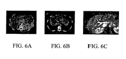
- FIGS. 6A-6C are CT scans of a liver
- FIGS. 7A-7C illustrate exemplary liver vessel models extracted using a vessel modeling technique according to an embodiment of the subject matter described herein;
- FIG. 7D illustrates a liver, its vessels, and a right lobe segmented from a CT image using blood vessel and tissue surface modeling technique according to an embodiment of the subject matter described herein;
- FIGS. 8A and 8B illustrate calibration images used to calibrate an ultrasound scanner for acquiring target image data
- FIG. 9 is a liver ultrasound scan illustrating the result of identification of occluded regions in the ultrasound scan according to an embodiment of the subject matter described herein;
- FIG. 10 is a graph of changes a in registration metric for a range of x offsets and xy plane rotations given vessels from a liver MR scan applied to a 3D ultrasound scan according to an embodiment of the subject matter described herein;
- FIGS. 11A and 11B show ultrasound scans overlaid onto different slices of an MR scan according to an embodiment of the subject matter described herein;
- FIG. 11C illustrates vessel models from an MR scan overlaid on an ultrasound scan according to an embodiment of the subject matter described herein;
- FIG. 12A is a computer image of a tub of gelatin and soba noodles used to test a method for liver vessel registration according to an embodiment of the subject matter described herein;
- FIG. 12B is a computer image illustrating results of vascular registration of the image illustrated in FIG. 12A ;
- FIG. 13A is a computer image illustrating the results of global rigid alignment between a vascular model from a post-operative scan directly with a pre-operative scan according to an embodiment of the subject matter described herein;
- FIG. 13B is a compute image illustrating the results of piecewise rigid registration between a vascular model from a post-operative scan with a pre-operative scan according to an embodiment of the subject matter described herein;
- FIG. 13C is a computer generated image illustrating the results of piecewise deformable registration of a vascular model from a post operative scan with a pre-operative scan according to an embodiment of the subject matter described herein;
- FIG. 14A is a computer image illustrating liver vessels from two CT scans taken six months apart before registration
- FIG. 14B is a computer image illustrating liver vessels from two CT scans after deformable registration according to an embodiment of the subject matter described herein;
- FIG. 15A is a diagram illustrating an exemplary pre-operative blood vessel model
- FIG. 15B is a diagram illustrating an exemplary intra-operative blood vessel model
- FIG. 15C is a diagram illustrating local changes to match the model from FIG. 15A to the image of FIG. 15B ;
- FIG. 15D is a diagram illustrating swirl induced by smooth interpolation of the deformation field produced by mapping a model in FIG. 15A to the image of FIG. 15B ;
- FIG. 15E is a diagram illustrating deformation field interpolation considering the limited basis of each gradient of FIG. 15D ;
- FIG. 16 is an image illustrating portions of a liver surface where arrows indicate strong gradients.
- FIG. 17 illustrates power graphs used to evaluate the accuracy of the registration methods described herein.
- FIG. 1 illustrates such a system.
- a blood vessel and tissue surface model generator 100 receives source blood vessel and tissue surface image for a subject.
- the source blood vessel and tissue surface image may be an MR image, a CT image, or any other type of image in which blood vessels and tissue surfaces can be distinguished from other features.
- Blood vessel and tissue surface model generator 100 generates a vascular model and a tissue surface model based on the source blood vessel and tissue surface image.
- An exemplary method for producing a vascular model and a tissue surface model will be described in detail below.
- the system illustrated in FIG. 1 also includes a hierarchical blood vessel and tissue surface model-to-image registration module 102 for registering the models generated by blood vessel and tissue surface module generator 104 with target blood vessel and tissue surface images for the subject using hierarchical piecewise and global registrations.
- Hierarchical blood vessel and tissue surface model-to-image registration module 102 may receive the models and target blood vessel and tissue surface images for a subject.
- Hierarchical blood vessel and tissue surface model-to-image registration module 102 may also receive a location or feature of interest in the source blood vessel and tissue surface image to be mapped into the target blood vessel and tissue surface image.
- the location or feature may be the location of a tumor or an notation made by a physician that corresponds to tumor margins.
- Hierarchical blood vessel and tissue surface model-to-image registration module 102 may apply a series of hierarchical rigid and deformable registrations to produce a model with a target-image-registered location or feature of interest. For example, in registering a pre-operative MR image of a liver tumor with an intra-operative image of the liver, hierarchical blood vessel and tissue surface model-to-image registration module 102 may utilize the transformations between the locations of the blood vessels and the tissue surfaces to determine the transformation in the location of the tumor from the pre-operative image to the intra-operative image.
- the registrations performed by hierarchical blood vessel and tissue surface model-to-image registration module 102 are hierarchical in the sense that blood vessel models in the blood vessel and tissue surface model are mapped to blood vessels in the target image starting from a trunk of each blood vessel and continuing along successive branches of each blood vessel.
- blood vessels in the human vasculature form tree like structures.
- the hierarchical blood vessel model-to-image registration method according to the subject matter described herein first registers the trunk of a vessel in the model with a trunk of a vessel in the image. Branches that are children of the trunk are registered along with the trunk. Next, the branches and sub-branches are registered in a hierarchical manner. Piecewise rigid and deformable registrations are both performed in this manner.
- FIGS. 2A-2F illustrate hierarchical registration between a blood vessel model and a blood vessel image according to an embodiment of the subject matter described herein.
- a blood vessel model 200 includes a root 202 and a single branch 204 .
- a blood vessel image 206 includes a root 208 and a single branch 210 .
- root 202 of blood vessel model 200 is translated to the location of root 208 of blood vessel image 206 .
- branch 204 of blood vessel model 200 is rotated about branch point 212 to correspond to the location of branch 210 of blood vessel image 206 .
- FIGS. 2A-2D are referred to as rigid transforms because only translations and rotations are performed. That is, a root and branches of in blood vessel model 200 are translated or rotated to correspond to locations of a root and branches blood vessel image 206 .
- the rigid transformations of FIGS. 2A-2D may be repeated for branches and sub-branches in a vessel tree until a model is rigidly registered with an image.
- FIGS. 2E and 2F illustrate hierarchical deformable transformations between a blood vessel model and a blood vessel image.
- root 202 of blood vessel model 200 is deformed to correspond to the shape of root 208 of blood vessel image 206 .
- branch 204 of blood vessel model 200 is deformed to correspond to the shape of branch 210 of blood vessel image 206 .
- the deformable transformations may be performed in a hierarchical manner on sub-branches until a blood vessel model is deformably registered with a blood vessel image. By performing the registration in a hierarchical manner model-to-image registration time is decreased and registration accuracy is increased.
- FIG. 3 is a flow chart illustrating exemplary steps for registering a vascular model with a vascular image according to an embodiment of the subject matter described herein.
- a vascular model is mapped to a target image using a global rigid transformation.
- vessels in the global-rigid-transformed vascular model are mapped to vessels in the target image using piecewise rigid transformations.
- the vessels are mapped in a hierarchical manner from root to branches to sub-branches as illustrated in FIGS. 2A-2F .
- the vessels in the piecewise-rigid-transformed vascular model are mapped to vessels in the target image using piecewise deformable transformations.
- the deformable transformations are also performed in a hierarchical manner as described above.
- FIG. 4 is a flow chart illustrating exemplary steps for combining tissue surface model-to-image registration with blood vessel model-to-image registration according to an embodiment of the subject matter described herein.
- a vascular model and a tissue surface model are generated from image data for a subject.
- a global rigid registration is performed between the vascular and tissue surface models and a blood vessel and tissue surface image for a subject to form a first transformed vascular and tissue surface model.
- the registration in step 402 may be performed such that the registrations for the vascular and tissue surface models are simultaneously optimized.
- step 404 hierarchical piecewise rigid registration is performed between blood vessels in the first transformed vascular model and blood vessels in the target image to form a second transformed vascular model.
- Step 404 is the same as step 302 illustrated in FIG. 3 .
- step 404 it is necessary to determine how to move the tissue surface model based on movements in the blood vessels in the vascular model.
- Two options are illustrated in FIG. 4 for registering the tissue surface model after the piecewise rigid blood vessel registration.
- One option is illustrated in step 406 A where the deformation field produced by the second vascular transformation (step 404 ) is extrapolated to obtain a second transformed tissue surface model.
- FIG. 406B where a global rigid registration is performed between the tissue surface model and the tissue surface image to form the second transformed tissue surface model.
- step 408 a hierarchical piecewise deformable registration is performed between the second transformed vascular model and the target image to form a third transformed vascular model.
- Step 408 is the same as step 304 illustrated in FIG. 3 .
- step 410 a global deformable registration is performed between the second transformed tissue surface model and the target image to form a third transformed tissue surface model.
- step 412 the third transformed vascular model and the third transformed tissue surface models are combined to form a third transform vascular and tissue surface model.
- the result is a model in which the vessels and tissue surfaces are transformed from the source image data to the target image data.
- a deformation field interpolation is performed to transcribe features of interest in the source image data to the third transformed vascular and tissue surface model.
- Steps 402 - 414 may be continually repeated during surgery or other time period in order to continually update registration between the vascular and tissue surface model and the target image as the target image changes. Because the registration is hierarchical and includes both rigid and deformable transformations, the resulting registration is both more accurate and more rapidly converging than conventional image-to-image registration methods. Exemplary methods for performing the steps illustrated in FIG. 4 will now be described in detail.
- Blood vessel modeling may be performed using any suitable method that extracts a blood vessel model from blood vessel image data.
- a three-dimensional blood vessel modeling or segmentation method may include performing a multiscale extraction of the centerline of a vessel and then estimating the radius of the vessel about the centerline. Specifically, the method involves three steps:
- tissue surface modeling As illustrated above in FIG. 4 , the subject matter described herein includes tissue surface modeling, registering tissue surface models with tissue surface image data, and combining tissue surface model-to-image registration with vascular model-to-image registration.
- tissue surface modeling As illustrated above in FIG. 4 , the subject matter described herein includes tissue surface modeling, registering tissue surface models with tissue surface image data, and combining tissue surface model-to-image registration with vascular model-to-image registration.
- the following sections illustrate examples of blood vessel and tissue surface modeling and model-to-image registration for using human liver image data as an example.
- the input to the present liver surface and vessel extraction methods can be any suitable image in which vessels, tissue surfaces, and features of interest are identifiable, such as CT or MR scans.
- CT scanner used in the examples described herein is a Siemens Sensation 16 multi-detector unit. Liver scans are acquired 30 and 60 seconds after contrast injection to help distinguish portal from hepatic vessels.
- FIGS. 6A-6C illustrate CT images of the liver used in this example. More particularly, FIG. 6A illustrates one slice from a portal-phase contrast CT scan. FIG. 6B illustrates one slice of a hepatic-phase contrast CT scan acquired 30 seconds after the portal phase scan. FIG. 6C illustrates one slice from a subtracted 3D VIBE MR scan.
- Voxel size is 0.56 ⁇ 0.56 ⁇ 1.5 mm.
- a 3D VIBE sequence on the Siemens 1.5T Sonata MR scanner was used for MR imaging of liver parenchyma and vasculature. This 17-second contrast-enhanced acquisition sequence can capture liver volume and vasculature at 0.6 ⁇ 0.6 ⁇ 2.5 mm.
- a pre-contrast VIBE scan from a VIBE scan acquired 23 seconds after gadolinium contrast injection ( FIG. 6C ).
- the semi-automated liver surface segmentation process is a sequence of connected component and morphological operations (Aylward 2002a) that has been shown to be faster and more accurate than hand segmentation (Weeks 2001). Specifically, (1) from a user-specified starting point and using lower and upper intensity thresholds specified by the user, the voxels spatially connected to the starting point and having intensities within the thresholds are identified (this is the standard connected components technique). (2) That component is pruned via erosion using a spherical operator to remove sections that are only connected by thin strands to the main components. The main component is subsequently dilated by the same amount to return it to its original borders (minus its clipped regions).
- the present semi-automated process requires approximately 1 minute per item and estimates the volumes to within 10% of ideal; on the same data, hand contouring requires up to 15 minutes per item and averages 20 % error (Weeks 2001).
- This semi-automated segmentation process while effective, is not critical to the success of the present system; manual contouring could be used to generate the surface model needed for feature-image registration.
- the present semi-automated method has been used to segment livers from over 20 subtracted VIBE scans and 80 liver CT scans with excellent results.
- a mathematical model of a tortuous vessel was created and three different magnitudes of Gaussian noise were added to its image data.
- the vessel had a radius of 4 voxels at its ends and 0.5 voxel at its middle. At its middle it branched.
- the branch was optimally difficult—each branch was identical and only spanned one voxel.
- the present dynamic-scale ridge traversal method was applied using different initial scales and 200 randomly chosen starting points within the object. Average time to extract 20 voxels of centerline was about 0.3 seconds.
- Capturing vascular movement is critical to capturing deformations internal to the liver, and the level of detail provided by the present pre-operative models is well beyond what has been used by others.
- Surface models alone are insufficient since only a small segment of the liver surface is captured in each ultrasound scan, and it may be difficult to correlate surface movement with deformations internal to the liver.
- (King 2001a,b) limited vessel models to manually specified centerlines of the major portal vein and the inferior vena cava, and (Porter 2001) used simple thresholding to find bright voxels indicative of vessels in MR and Doppler ultrasound.
- FIGS. 7A-7D Examples of the application of the present liver surface and vessel segmentation methods are given in FIGS. 7A-7D . More particularly, FIG. 7A illustrates a vessel tree extracted from a portal-phase contrast CT scan. FIG. 7B illustrates a vessel tree extracted from a hepatic phase contrast CT scan. FIG. 7C illustrates a vessel tree extracted from pre/post 3D VIBE MR sequences. FIG. 7D illustrates a liver, its vessels, and right lobe segmented from a CT scan. The 3D visualizations illustrated in FIGS. 7A-7D may be useful for partial liver transplant planning. The other source of data in ultrasound annotation: the intra-operative ultrasound data, will now be discussed.
- Target images to which the hierarchical model-to-image registration methods may be applied can be obtained from any suitable source.
- a Meduson Voluson 530D 3D ultrasound system was utilized to obtain ultrasound images of the liver for the present method.
- the strength of the Voluson 530 scanner is that it acquires 3D ultrasound scans without requiring the operator to perform a sweeping motion—the linear transducer internal to the probe is automatically swept to acquire the 3D data.
- these 3D scans are FDA approved for volume and other 3D measurements. Self-contained, automated 3D sweeping greatly simplifies the mental and physical demands placed on the clinician and reduces the risk of spatial errors.
- Voluson 530 One complication with the Voluson 530 is that scans require 7 to 15 seconds to be acquired. Given that the PLL-RFA patients are often not under respiratory control, 7 to 15 second scans are likely to suffer from intra-scan organ movement. A Volu son 730 scanner that offers sub-second scan times may be used to perform the scans.
- FIGS. 8A and 8B To measure the spatial accuracy of the present 3D ultrasound scanner, a Rammex RMI 403GS (Middleton, Wis.) calibration phantom ( FIGS. 8A and 8B ) was used. After Cartesian resampling by the Voluson system, 3D scans captured distances within one voxel throughout their entire volume—accuracy did not vary for deep or off-center targets. Nevertheless, in liver acquisitions, as the ultrasound pulses pass through heterogeneous tissues, spatial distortions may occur. These distortions, however, will have equal effect on the apparent position of the needle, liver surface, and liver vessels within the ultrasound data. Since the present methods are primarily concerned with the relative locations of these objects, the ultrasound distortions should have minimal effect on physician performance or accuracy when using ultrasound annotation.
- the present example did not involve the acquisition of Doppler ultrasound images.
- the Voluson 530 produces very poor quality Doppler ultrasound images.
- Doppler ultrasound images have been determined to be unacceptable for clinical use, and review has showed that the quality and quantity of the vessels captures with Doppler is less than what is available in its b-mode images.
- the GE Voluson 730 provided significantly better 3D Doppler images.
- the present method would be more broadly applicable if 3D Doppler images wasn't required since not all 3D acquisition techniques can provide them, e.g., the popular Stradx software for creating 3D ultrasound images cannot create 3D Doppler images.
- Ultrasound probe tracking cannot account for organ changes between pre- and intra-operative image acquisitions, intra-operative patient movements, internal organ movement, or organ deformations; however, the present method will track the 3D ultrasound probe when ultrasound data is acquired and then use the tracker data to initialize the registration of the ultrasound data and the pre-operative models.
- the tracker data provides rigid transforms that capture relative probe movements between subsequent ultrasound scans. That rigid transform is compounded with the previously resolved image transform to initialize the next image registration process.
- One exemplary tracker suitable for use in tracking an ultrasound probe is a Flock-of-Birds magnetic tracker (Ascension Technologies).
- the sensor is fixed to the end of a rigid, 15.5′′ long piece of plastic that has an extruded triangle shape. At the other end, an aluminum ring passes through the plastic and can be tightened around the ultrasound probe handle.
- This setup has been determined to be particularly stable and broadly applicable. This setup, however, requires calibration of the relationship between the sensor and points in the ultrasound data.
- a 5 ⁇ 5 ⁇ 5 cm pyramid-shaped wire-frame object was constructed. It is placed in a bucket of water, and three or more tracked 3D ultrasound scans are acquired. The location and orientation of the object in each scan is determined using a generalized Hough transform (Ballard 1981).
- the present method solves (using a squared-error minimization technique initialized with expected values) for the transformation matrix that can be compounded with each tracker position to align their object representations.
- Repeated calibrations of the same probe/sensor setup were performed.
- the standard deviation of four repeated calibrations was 0.145 mm and the maximum difference from the mean was 0.168 mm.
- Another possible source of magnetic tracker error is field deformation due to metal moving near the sensor. The present studies indicate that this error may be significant.
- a tracker sensor sitting on a surgical bed beside a patient will appear to move as much as 11 mm when a 24-gage biopsy needle is moved near it.
- Such additional uncertainty in registration initialization adds to the time required perform the image registration process.
- an optical tracker may therefore be desirable to use an optical tracker to track the ultrasound probe and thereby accurately initialize registration.
- Using an optical tracker will allow focus on the primary purpose for image registration in ultrasound annotation, i.e., accounting for liver deformation due to patient movement, organ movement, breathing, needle pressure, etc. that external tracking cannot capture.
- the present registration metric quantifies how well a transform aligns liver surface and vessel models from pre-operative data with intra-operative ultrasound images.
- the present metric uses the physics of ultrasound acquisition when specifying the type of measures to be made in the ultrasound images. For example, since vessels appear as dark tubes in 3D ultrasound images, when a vascular model is aligned with an ultrasound image, the centerline points of the model will map to dark voxels in the image. Similarly, organ surfaces form bright or high gradient surfaces in ultrasound images, dependent on the orientation of the ultrasound probe with respect to the orientation of the surface. However, occluded regions are also commonly present in ultrasound data, and vessel/surface features will not be visible in those regions. Therefore, prior to initiating intra-operative registration, it is necessary to identify occluded regions and exclude them from influencing the registration process.
- Occluded region identification The present subject matter includes a method for rapid identification of occluded regions in ultrasound images.
- the occluded regions are designated as don't care regions so that features that map into those regions will neither dilute the match metric nor create false local metric maxima.
- the primary emphasis during occluded region masking is speed; underestimating an occluded region is allowed since the present registration method is insensitive to missing features (Aylward 2003).
- the present occluded region masking method operates by down-sampling the 3D ultrasound images from 256 ⁇ 256 ⁇ 256 to 64 ⁇ 64 ⁇ 64 (requires 0.64 seconds) and then convolving that sub-sampled image with a 1D Gaussian derivative kernel oriented approximately along the ultrasound wave propagation direction (via table lookup).
- the intensity and gradient magnitude are then thresholded to identify points within the occluded region. Thresholds were chosen based on observations from multiple 3D ultrasound scans; the thresholds have worked on every subsequent scan without modification.
- the resulting mask is then up-sampled to 256 ⁇ 256 ⁇ 256 using nearest-neighbor interpolation. Convolution, thresholding, and up-sampling requires 1.86 seconds. Total computation time is ⁇ 2.5 seconds. This processing was implemented using ITK, the National Library of Medicine's Insight Toolkit for Medical Image Segmentation and Registration: www.itk.org. ITK provides multi-threading and data streaming—with the requested dual-processor machine, the computation time should be reduced by 40-50%. Results are illustrated in FIG. 9 . More particularly, FIG.
- FIG. 9 illustrates a 3D mask computed using the method described in this paragraph.
- the computation of the 3D mask in FIG. 9 required 2.505 seconds.
- the robustness of the present registration process allows for the underestimation of the occluded region. Emphasis was therefore placed on speed.
- Vascular Feature-Image Match Metric One exemplary metric suitable for use with the subject matter described herein quantities the match between pre-operative vascular models and the intra-operative ultrasound image data. Again, the present implementation focuses on vascular features since they have received the least attention by other groups, and yet they may be best at capturing deformations internal to the liver.
- the vascular feature-image match metric is given by:
- the data is scaled (blurred using a Gaussian having a standard deviation of kr i ) to increase the conspicuousness of tubular intensity structures of radius r i (Aylward 2002a, Lindeberg 1994).
- the intensities in the ultrasound image are inverted to make the vessels appear brighter than the background, thus the metric is maximal when the vessel models are registered with the image.
- the weightings are changed during registration to first favor large vessels and then to include smaller vessels. Not portrayed in this equation is the additional constraint that any centerline point that is transformed into an occluded region is not included in the calculations. An analysis of these parameters is provided in (Aylward 2001, 2003).
- FIG. 10 is a graph of the metric for +/ ⁇ 20 voxels of x-offset and +/ ⁇ 0.2 radians of xy-plane rotation, given the vascular model in FIG. 7C from the MR scan in FIG. 6C and the 3D ultrasound data with the masked occluded region in FIG. 9 . More particularly, FIG. 10 illustrates the change in metric value for a range of x offsets and xy plane rotations given vessels from a liver MR scan applied to a 3D ultrasound scan. The zero coordinate was determined by an initial registration using vessel based feature-image registration. The metric has a global maximum at registration (the zero coordinate) and no erroneous local maxima for a wide range of offsets and rotations.
- this metric is extended to include surface models and measures. Additional aspects of the physics of ultrasound acquisition will also be described.
- the present implementation includes a coarse-to-fine deformable registration.
- coarse-to-fine registration is implemented using an image pyramid, a sequence of sub-samplings.
- the underlying assumption is that the objects throughout the image have equal coherence across those scales; yet, objects exist at different scales in images.
- blood vessels inherently provide a natural coarse-to-fine hierarchy as tree structures. In the liver the portal and hepatic vessels form two distinct trees.
- one exemplary deformable transform optimization process includes three steps.
- the first step is global rigid registration using a vessel-image metric (Aylward 2001, 2002a, 2003).
- the second step consists of a piecewise rigid registration process applied hierarchically from vessel tree roots to leaves.
- the third step is a piecewise non-rigid deformation process that is also applied from vessel tree roots to leaves.
- the two last steps are unique, and their use of the vessel hierarchy supports fast registration by eliminating the need to compute intra-operative image pyramids.
- the present deformable registration strategy is initiated by solving for a global rigid transform that maps the pre-operative models into the intra-operative ultrasound data (Aylward 2001, 2002a, 2003).
- a unique property of the present method is that it limits vessels to inducing registration updates in their normal directions.
- the iterative updates of the rigid transform are adjusted for the orientation bias of the vessels. For example, if most of the vessels in the network have a horizontal orientation, the total vertical update they induce is down-weighted so that horizontal alignment updates can have equal force.
- This registration process achieves consistent, sub-voxel convergence from 0.2 radians of mis-rotation and 20 voxel offsets in 2-3 seconds for MR to ultrasound registration.
- the present rigid registration implementation involving only vasculature, operates as follows.
- a matrix N i is defined to specify the plane normal to each transformed vessel centerline point.
- the spread of the normal planes is calculated for the subsampled centerline points as a global bias matrix
- the bias matrix B is invertible as long as all of the vessels in a network are not parallel.
- the unbiased gradients from Equation 7 are then used to determine updates to transforms parameters that maximize the metric. For example, offset vector updates ⁇ during registration optimization are defined as the weighted sum of the unbiased, projected gradients.
- Piecewise rigid registration After global rigid registration, a rigid transformation is calculated to refine the position of each vessel, in a hierarchical manner. First, if a root of a vascular tree overlaps with the ultrasound image after global rigid registration, its position and orientation (independent of other vessels) is refined using a rigid transform and the metric. Vessels spanning more than 20 voxels are broken into 20 voxel segments. Second, each root's branches are registered rigidly with the image, one branch at a time, using the tree's parent-child hierarchy and using branch points as anchor points. Again, only those branches that were determined to overlap the intra-operative image, based on the global rigid transform, are used, and long vessel segments are broken into shorter vessel segments.
- each branch its rotation about its branch point is solved iteratively using the present vessel-image metric (Equation 3 and (Aylward 2001b, 2003)).
- Each branch's rotation is computed independently, and its descendants do not contribute to the metric.
- the weightings of the points in each branch's model decrease based on their distance from the branch point.
- a branch's translation is constrained to be along its parent. Specifically, the translation vector of the child is projected onto the tangent direction of its parent vessel at the branch point, and the amount of translation allowed is constrained by an “elasticity” property of the parent vessel; translation updates are dampened by how much a branch point has been translated from its initial location. Updates use a gradient ascent optimization strategy. While appearing complex, the multiple constraints involved reduce the complexity of the transformation's parameter space and thereby speed the registration process; this step requires only ⁇ 5 seconds.
- Piecewise non-rigid of deformable registration parallels the rigid registration step.
- the image gradient is computed at a scale proportional to the radius of the local vessel point and projected onto the normal of the vessel point to determine how that vessel point should move, as was done for rigid registration in (Aylward 2001, 2002b, 2003) (Equation 5).
- a “rigidity” coefficient that dampens vessel bending is added. Specifically, it dampens updates based on the difference between the initial curvature at a vessel point and the current curvature at that point.
- This rigidity coefficient varies along a vessel, proportional to the radius of the vessel (it and “elasticity” could also depend on the material properties of the vessel and liver, but such precision is unnecessary for image-driven registration).
- this rigidity value is kept constant at every point, and the sampling rate along a vessel is used to accommodate the coefficient as the radius changes (Equation 3).
- Total deformable registration time is 20-30 seconds.
- the model's transform is interpolated to transcribe pre-operative markings, such as desired PLL-RFA sites, into the intra-operative ultrasound data.
- a deformation field vector value D at a point x is estimated using the method in (Pennec 2003), i.e., using Gaussian interpolation of the update vectors d i at model points x i as follows
- Deformation field interpolation is an instance of deformation field regularization; this class of methods has been the focus of much research. Excellent iterative, large-deformation diffeomorphic field generation, and finite element model based techniques have been developed for deformation field regularization (Joshi 2000). These methods, however, tend to be dense field techniques—it is necessary to solve for many (often all of the) points in a deformation field to determine the deformation field at any particular point.
- Equation 9 has been used (King 2001a,b; Pennec 2003) for intra-operative deformation field interpolation since it is only necessary to evaluate it at the PLL-RFA points to determine how to translate them into the ultrasound's coordinate system. This computation is fast and produces acceptable results under the assumption that the deformations are small and smooth—this is likely the case for ultrasound annotation for minimally invasive procedures such as PLL-RFA. Nevertheless, there are problems with Equation 9; it lacks consideration of the fact that model deformation vectors d i only capture the normal-direction components of the underlying deformation field—by design, they lack the tangential component (Equations 4-8). The present solution is applicable to many of the model, active-contour, active-surface, active-shape and sparse-field deformation strategies that limit model updates to normal directions.
- Liver motion due to breathing is the likely source of much of the intra-operative liver displacement.
- a portal-phase CT scan at maximum breath inhale and a hepatic-phase CT scan at maximum exhale was acquired.
- the vessel models from the portal scan were modeled, and those models were then registered with the hepatic scan using the present rigid registration strategy.
- the resulting transform parameters are given in Table 1.
- the liver translates to the posterior and rotates to the inferior along a sagittal course. Total movement is about 1 cm and 0.09 radians.
- FIG. 11A and 11B illustrate two ultrasound scans overlaid on two different slices of an MR scan. These scans were aligned by registering a vascular model from the MR scan with each ultrasound scan. Vessel and liver surface correspondences are indicated by arrows. In FIG. 11C , vessel models from the MR scan are overlaid on an ultrasound scan. Shadowing is evident in nearly one half of this slice, but registration was consistent as illustrated in Table 2 below.
- the proposed extensions are expected to reduce the failure rate to zero and to improve both accuracy and consistency.
- the registration method's accuracy is evaluated.
- a tub of gelatin containing soba noodles and four 5 ⁇ 5 ⁇ 5 mm targets was scanned in a CT system using a standard liver protocol.
- a model of the vessels/noodles was extracted from that scan.
- An ultrasound scan with an RFA needle inserted through the center of the tub was then acquired.
- the CT vessel models were roughly rigidly registered with that ultrasound scan using a calibrated magnetic tracker.
- the centers of mass of the four targets were calculated in each scan The mean distance between those centers across the roughly registered scans was 8.8 mm and the max distance was 9.8 mm.
- the vascular registration system was then used to refine the alignment of the CT model with the ultrasound data. This registration required ⁇ 2 seconds.
- FIG. 12A is an image of the tub of gelatin and soba noodles. It was determined that a tub of gelatin and soba noodles has CT properties within a few HU of liver CT properties. Vessels were extracted from Cr scan and then registered with the ultrasound scan.
- FIGS. 13 and 14 Two vessel networks are shown.
- the dark grey (post operative) vascular models are being deformably registered with the MRA image data used to generate the light grey (pre-operative) vascular models.
- the light grey models are not used in the registration.
- FIG. 13A illustrates the results of globally rigidly aligning a vascular model (dark grey) from a post-operative scan directly with a pre-operative scan (not shown-instead its vessel are shown by light grey to reveal registration accuracy).
- FIG. 13B the results from piecewise rigid registration are illustrated.
- FIG. 13C the results from piecewise non-rigid registration are illustrated.
- the circles indicate an area of large deformation. Average distance between the vascular networks is sub-voxel.
- FIGS. 14A and 14B liver vessels from two CT scans taken six months apart are shown. Two vessel networks are shown, but the dark gray vascular model is being deformably registered with the CT image data used to generate the light grey vascular model.
- FIG. 14A illustrates the model and image before registration.
- FIG. 14B illustrates the image and vascular model after deformable registration.
- the mean distance between the deformed and the data's actual vascular network is 0.66 mm.
- the time required for registration is less than 30 seconds.
- pre- and post-operative MR or CT scans and intra-operative 3D ultrasound scans will be collected from 20 patients per year. The first five patients enrolled each year will be used for system development; the other 15 will be reserved for the evaluations. Therefore, at the end of three years, 15 patients' data will be available for training and 45 for testing. They will be grouped and made available from a web site as such. Details regarding the pre-operative MR/CT and intra-operative 3D ultrasound are described below.
- Pre-operative CT/MR It is necessary to acquire MR/CT scans of PLL-RFA patients to form pre-operative liver vessel and surface models to be used during registration. Most PLL-RFA patients come from outside referral, and electronic access to their prior CT/MR scans is generally not available. Randomly, but possibly modified by consent and health status, such as creatine levels, half of the patients will be assigned to receive a pre-operative MR and half will receive a pre-operative CT.
- All CT scans will be acquired on a Siemens Sensation 16 multi-detector CT unit using a liver donor evaluation protocol.
- the portal and hepatic phase scans are acquired 30 and 60 seconds after contrast injection to capture portal and hepatic vessels details respectively. These scans are registered to generate a model that contains both vascular networks. These scans contain approximately 512 ⁇ 512 ⁇ 280 voxels with a voxel size of ⁇ 0.56 ⁇ 0.56 ⁇ 1.5 mm.
- MR scans will be acquired on a Siemens Sonata 1.5 T MR unit using a 3D VIBE sequence.
- This high gradient, 1.5 T magnet supports fast and detailed 3D and thin-slice images.
- the VIBE sequence is a T1 weighted 3D Flash breath-hold technique.
- Three-dimensional Fourier transform GRE imaging has potential advantages over 2D imaging. In comparison with traditional 2D GRE sequences, properly structured 3D GRE sequences have the capacity to provide thinner sections, no gaps, fat saturation, higher SNR, and comparable image contrast in the same breath-hold time frame.
- Data can be acquired transverse and dynamically (pre-contrast, arterial phase, early portal venous phase and late portal venous phase) with a single dose of gadolinium.
- a pre-contrast scan is subtracted from a late portal venous phase image to emphasize vascular detail.
- These images cover the liver in a 512 ⁇ 512 ⁇ 200 voxel volume with contiguous ⁇ 0.6 ⁇ 0.6 ⁇ 2.5 mm voxels.
- a potential problem with abdominal MR is spatial distortion; however, since it is only necessary to capture the relative relationship between the liver's surface and vessels and the desired RFA sites in the MR data, if the MR distortions are not locally severe, it is not necessary to correct for them—deformable registration with the ultrasound data will still be valid—the relative locations of the image features will still be maintained.
- the proposed studies will be restricted to the use of CT. This is a reasonable fallback position, but the subject matter described herein can be used with MR images.
- Intra-operative 3D ultrasound 3D ultrasound scans will be acquired during PLL-RFA procedures: for each designated tumor one scan will be collected prior to needle insertion, two scans will be collected after needle insertion while en-route to the tumor, and one scan will be collected immediately prior to ablation initiation. It is preferable to use an ultrasound spacer on thin patients so that a larger portion of the liver surface near the ultrasound probe is captured and available for registration. Also, both b-mode and Doppler images will be acquired to compare their vascular detail and effect on registration performance in Aim 4. A GE Voluson 730 ultrasound machine may be used for these acquisitions.
- the GE 730 offers reduced (sub-second versus 7-15 second) scan times and Doppler capabilities. Faster scan times will reduce the amount of intra-scan organ movement that would degrade registration accuracy and consistency. Doppler scans are likely to provide improved vascular detail leading to improved registration accuracy. All scans are automatically stored in isotropic Cartesian coordinates using ⁇ 0.6 ⁇ 0.6 ⁇ 0.6 mm voxels. DICOM will be used to push each scan to a workstation.
- ultrasound probe tracking cannot account for organ changes between pre- and intra-operative image acquisition, intra-operative patient movement, organ movement (particularly due to breathing), or organ deformations; however, the 3D ultrasound probe will be tracked when ultrasound data is acquired to initialize the registration of the ultrasound data and the pre-operative models by providing relative rigid transforms between consecutive ultrasound scans.
- the calibration protocol detailed above may be used. Since the present preliminary results demonstrate magnetic tracker interference from the RFA needle, an optical tracker may be more suitable for this purpose.
- the present method is based on a consistent philosophy for the simultaneous consideration of vasculature and surfaces for model-to-image registration.
- the preliminary implementation focused on understanding and evaluating the potential of vasculature in intra-operative registration for ultrasound annotation.
- Vasculature has only received limited attention in intra-operative ultrasound registration (King 2001a,b; Porter 2002), but it has amazing potential: vasculature moves as the surrounding tissues move, are dense throughout the liver, and are clearly visible on ultrasound.
- there is also a clear role for surfaces in registration surface deformation ensures that estimating a deformation field only requires interpolation and not extrapolation to cover an organ.
- an intra-operative ultrasound annotation system that embodies this philosophy will be implemented.
- the steps of the present ultrasound annotation method are (a) pre-operative CT/MR liver vessel and surface modeling, (b) pre-operative desired PLL-RFA site specification, (c) intra-operative deformable registration, and (d) intra-operative desired PLL-RFA site transcription.
- the basic processes and capabilities of these steps are described above. Here the modifications needed to incorporate surfaces into those processes are described.
- Pre-operative Desired PLL-RFA Site Specification The interventional radiologist who will perform the PLL-RFA procedure will specify the desired needle destinations via point-and-clicks within the pre-operative image slices. These will be recorded using software developed for liver transplant planning. Many intra-operative factors determine the appropriate approaches to those sites, so only the sites and not the paths to those site can and will be specified on the pre-operative data.
- Intra-operative deformable registration progresses in three steps: global rigid, piecewise rigid, and then piecewise deformable registration. Underlying all three is a common metric. Here the extension of the metric (Equation 3) to include surfaces is described. The corresponding extensions to the steps of registration are also described.
- Vessel/Sufface Feature-Image metric The present surface registration metric assumes that surface model points map to bright voxels within the target image when the model and image are registered; just as vessel model points should map to the dark voxels in the image.
- the vessel-to-image match metric of Equation 3 is augmented to become a combined vessel/surface-to-image metric as follows:
- N i ⁇ j ⁇ T ⁇ ( n ji ) ⁇ T ⁇ ( n ji ) ⁇ ⁇ for ⁇ ⁇ all ⁇ ⁇ j ⁇ ⁇ normal ⁇ ⁇ directions ⁇ ⁇ n ji ⁇ ⁇ at ⁇ ⁇ x i ( 11 )
- ⁇ denotes the outer product operator.
- Piecewise rigid registration Initialized using the global rigid registration results, this step proceeds coarse-to-fine using the vascular tree hierarchy as described above. After vessel-based piecewise rigid registration, the surface is rigidly registered independently with the ultrasound image using gradient ascent and the metric in Equation 10.
- Piecewise deformable registration Initialized using the piecewise rigid registration results, the method solves for the deformable registration of the vessels to the ultrasound data and then uses their deformation field to initialize the deformable registration of the surface to the data.
- the process of piecewise deformable registration uses the natural hierarchical relationship between vessels (as tree structures) to implement a coarse-to-fine optimization scheme. First, the vascular roots are deformed to fit the data, and then their branches are deformed. This process requires 20-30 seconds. The vessel model deformations are extrapolated to the surface by evaluating the deformation field interpolation equation (Equation 9) at the surface points. The fit of the surface to the data is then refined using Equation 10 and a gradient ascent optimization strategy.
- the present surface deformation technique is a variant of explicit active surfaces that maximizes the integral of the scaled intensities it encounters while minimizing internal energy as measured by bending.
- This integrative surface and vessel registration process while simple, is novel, accurate, fast, and provides a consistent philosophy for handling vessels and surfaces that is absent from other intra-operative registration strategies. It is also extensible to include aspect of the physics of liver deformation and ultrasound acquisition.
- Deformation field interpolation via Equation 9 makes numerous assumptions regarding how local liver and vessel deformations combine to specify the movement of surrounding liver tissues.
- One motivation for the use of deformation field interpolation is described above. Here its limitations are discussed and corrected. In particular, an often-overlooked limitation/assumption is identified and an alternative is offered.
- Equation 9 Simple Gaussian interpolation, as in Equation 9, has limitations; the deformations must be small and smooth for the interpolated deformation vectors to be diffeomorphic and accurate. These limitations are well known. One often/completely overlooked assumption, however, is that the deformation vectors being interpolated are assumed to completely describe the deformation field at those points, and this is largely untrue.
- Equation 9 is corrected to enable the accurate interpolation of deformation fields given sparse, limited support, i.e., given deformation field values at model points where those values selectively capture only a subspace component of the local deformation field.
- each d i is weighted by the uniqueness of its basis N i compared to the total basis of all of the local deformation vectors d i that contribute to x.
- This total basis is a weighted sum of the normal matrices of the local model points:
- FIGS. 15A and 15B To visualize the importance of this approach, consider the non-rigid registration of a “pre-operative” image of a large circle with an embedded cross and an “intra-operative” image that contains a smaller circle and cross, with rotation, FIGS. 15A and 15B .
- the “correct” deformation from the pre- to the intra-operative image is ambiguous; many vector field transforms could be applied to map these images.
- the vector field implied is shown in FIG. 15C .
- Equation 9 a smoothing-based interpolation (Equation 9) is applied to determine how the space between the circle and the cross is deformed, the likely results is shown in FIG. 15 D—a swirl is introduced—this interpolation does not consider the orientation biases of the features in the image.
- the outer circle's local vectors tell us nothing about rotation and the inner cross' vectors poorly capture scale.
- the biases N i of points on the circle and points on the cross are orthogonal, so their gradient vectors should linearly combine, as in Equ. 14 and as shown in FIG. 15E .
- the resulting transform is nearly a similarity (rigid+scale) transform; a lower-order transform; it has a smaller Jacobean trace; it is more likely the underling process from A to B.
- Organ surfaces are visible in ultrasound images as intensity surfaces or gradient surfaces dependent upon the change in the acoustic properties across the organ surface and the orientation of the organ surfaces with respect to the ultrasound wave ( FIG. 16 ).
- the arrows indicate the portions of the liver surface that are represented via strong gradiance or bright intensities in the image.
- the image properties of surfaces and ultrasound vary by their orientation with respect to the ultrasound wave.
- the present enhanced metric accounts for this dependency.
- the influence of vessel and surface measures must be scaled to have equal influence on the metric.
- the present metric is modified to account for the interdependence between ultrasound wave direction and the surface normal orientation.
- the modification includes pre-computing the orientation of the ultrasound wave at every voxel in the 3D ultrasound data as u(x i ).
- the dot product between the wave orientation and the vessel point's transformed normal direction T(n 1i ) is computed to weight the local gradient and intensity image information at surface points.
- the method of dynamic intensity remapping of (Pennec 2003) is used to solve for the degree-two polynomial that rescales the vessel, surface, and liver intensities in an ultrasound image to match the expected values of those intensities as defined by a template ultrasound image.
- the ultrasound intensities are sampled where the transformed models suggest that vessel, surface, and liver intensities are present.
- the present method solves for the degree-two polynomial that brings them into closer correspondence with template means for those classes.
- a prior is used to constrain the parameters of the polynomial, and only small parameter changes are allowed at each step, as registration progresses.
- Template means are chosen by hand labeling vessel, surface, and liver points within a training ultrasound image. Pennec has shown this method to be effective not only for simple intra-modality (ultrasound-ultrasound) matching, but also for more complex MR to CT intensity matching. Once the intensities are matched across scans, the statistics needed to equate vessel intensities, surface intensities, and surface gradients can be computed so as to give those measures commensurate units as described next.
- the measures are converted to likelihood measures. Specifically, using the 15 scans reserved for system development, after matching their intensities using the method described above, the present method will measure the means and variances of the vessel (Equation 3) and surface (Equations 16 and 18) measures at model points after model-image registration and for random offsets and rotations from registration. Each value v of measure m is then scaled based on its signed distance from each mean, normalized by their variances, and then normalized by the spread of the means as follows
- the metric is defined by
- This metric considers surfaces and vessels, adjusts for ultrasound probe orientation, adjusts for inter-scan intensity variations, and normalizes the surface and vessel measures to have equal influence on the metric.
- the preliminary results show that the vessel component of this metric is fast and accurate for MR/CT to ultrasound registration.
- the computational costs and benefits of these extensions are determined.
- This section seeks to quantify how the proposed extensions aid in the speed and accuracy of CT/MR to ultrasound intra-operative registrations for PLL-RFA.
- the extensions will be compared using recorded, clinical PLL-RFA data.
- the accuracy of the image registration component of an ultrasound annotation system is quantified by how closely it can transcribe a point designated on pre-operative CT/MR data into its correct position in the intra-operative ultrasound data.
- the speed of the image registration component is measured by the time required to register an intra-operative 3D ultrasound image with a pre-operative CT/MR image.
- an interventional radiologists will designate the desired PLL-RFA sites on each of the 4 intra-operative 3D ultrasound images from the 45 patients designated for system testing. These are patients undergoing PLL-RFA treatment, so their tumors are visible on those scans as a clinical requirement.
- the interventional radiologists will have already (Aim 1) designated the desired PLL-RFA site on the pre-operative data for each tumor of interest.
- the present focus is not central tendencies or variance of accuracy, but instead the key statistics for clinical accuracy are the extremes; therefore, the present method focuses on the 95 th , 99 th , 100 th (maximum) quantities of error.
- One-way ANOVA (analysis of variance) tests will be conducted to compare the 24 possible combinations of the independent variables, where the dependent variables for comparison are the 95, 99, and 100 th quantile of the log-transformed distances between the transcribed desired PLL-RFA sites and their manually designated locations within the ultrasound data. The log-transformation is used to ensure the validity of normal assumption (Muller and Fetterman 2002, page 219).
- the key clinical statistics are the 95 th , 99 th , 100 th (maximum) quantile of the time to register the data.
- the above one-way ANOVA tests are repeated to compare the 24 possible combinations of the independent variables, where the dependent variables are the 95, 99, and 100 th quantile of registration time.
- the Tukey test will be used to compare the different levels for the independent variables, and 0.05/3 will be used for alpha.
- repeated measure ANOVA will also be used to analyze the data.
- Repeated measures ANOVA where the patient is the repeated measure unit, accounts for the correlations of the measures resulting from using multiple scans from the same patient.
- the outcomes in the analysis will be the log-transformed discrepancy distance and registration times based on readings from the tumors in all patients.
- the factor of each independent variable as well as their interaction can be analyzed. It will be possible to quantify how important physically based interpolation is to a vessel-only model as well as determine which is the most accurate and fastest method.
- each implementation's maximum error will be compared with the clinical goals of 5 mm maximum error as stated by others (King 2001a,b) and radiologists, primarily based on the desire for a 1 cm burn margin around each tumor.
- the subject matter described herein addresses the key component of image-based ultrasound annotation, intra-operative deformable registration of pre-operative CT/MR images with intra-operative 3D ultrasound images. It promotes the use of vascular and surface models from the pre-operative images to drive the registration process.
- One of its strengths is that those models specify the location, scale, orientation, and type of measure to be made in the intra-operative data to determine the validity of a transform.
- Those focused measures also specify how the parameters of the deformable transform should be updated to improve the registration of the pre- and intra-operative data. This makes the system uniquely accurate and fast.
- Extensions based on the physics of ultrasound acquisition and liver vessel and surface deformation are described herein. These extensions embody a philosophy that is applicable to other deformable registration strategies. Extensive and well-powered tests to compare the accuracy and speed of the base and extended implementations using clinical PLL-RFA data are also described. An ultrasound annotation system that meets radiologists' speed and accuracy requirements does not exist; preliminary results indicate the present implementation will be the first.
- the registration methods described herein may be used in any application in which it is desirable to rapidly register a blood vessel model with blood vessel image data. Examples of such applications include disease diagnosis, disease staging, surgical planning, transplant planning, etc.
Abstract
Description
-
- (1) definition of a seed point on or near a vessel of interest;
- (2) automatic, dynamic-scale extraction of an image intensity ridge representing the vessels central skeleton; and
- (3) automatic determination of a vessel's radius at each centerline point.
These steps will now be described in detail.
- Step 1: A seed point consists of a location x0 and a radius r0 estimate. These values can be specified manually (via points-and-clicks) or automatically using local contrast and ridge measures. An intensity ridge of a tube is defined as a 1D height ridge in 3D:
- Define: x as a point in the image (xε3)

- σ as the scale at which measures at x are made
- Iσ (x) as the image intensity at x at scale σ (subscript of an image indicates scaling)
- H as the Hessian matrix of I at x at scale σ
- vi and λi as the eigenvectors and associated eigenvalues of H with λ1≦λ2≦λ3
- If x is on a ridge, then
- v3 approximates the ridge's tangent direction at x, and
- v1 and v2 approximate the ridge's normal directions.
- (See Eberly, “Ridges in Image and Data Analysis,” Computational Imaging and Vision, Vol. 7, Kluwer Academic Publishers: Dordrecht (1996).)
- Therefore, for x to be a ridge point (i.e., on the centerline of a vessel), it must be true that:
- λ1≦λ2<0 Height-Ridge: The intensity decreases away from the ridge
- λ2/λ1≅1 Circularity: Cross-sectional intensity is nearly circular
- v1·∇Iσ(x)≅0 Ridgeness: The point is an extremum in the directions normal to the ridge
- v2·∇Iσ(x)≅0
- Using the eigenvectors of the Hessian to specify the directions in which the point is maximal makes this a “maximum-curvature” height-ridge definition. The scale σ is adapted during the traversal process that is explained next.
- Step 2: Given a seed point, the remainder of the extraction process is completely automated; three steps are repeated to traverse the extent of the vessel skeleton. (a) The approximate normal plane is shifted one fifth of a voxel along the ridge's approximate tangent direction. Assuming the ridge varies smoothly, the ridge will pass through this shifted normal plane. (b) The local maximum in intensity in that shifted normal plan is located. This point is the next point xi+1 on the ridge/central skeleton. (c) At fixed intervals during this traversal, the radius of the tube ri is estimated (in a manner similar to that in Step 3—next) and used to define σi+1, the scale at which subsequent ridge traversal measures are made. Once any of the height-ridge constraints is not satisfied, the traversal process terminates.
- Step 3: The central track stabilizes the estimation of the tube's radius. The radius at a point xi on a ridge can be defined by an initial radius estimate r=ri−1 via
r i=ArgLocalMaxr [M(x i , r)] (1)
where M(xi, r) is a medialness function. Medialness functions respond maximally when applied at the center xi of a gray-scale object and at a scale r proportional to the radius of the object. A medialness function that uses a weighted sum of five kernel convolutions can be used. The kernels are distributed along a centerline about xi, and each kernel is a radial sampling of a binary center-on/surround-off kernel oriented normal to its centerline point.FIG. 5 is a 3D rendering of a vascular model with a set of kernels distributed about the vessel centerline. InFIG. 5 ,kernels 500 are radially distributed aboutvessel model 502. Each kernel is a radial sample of a center-on/surround-off binary filter oriented normal to the centerline ofvessel model 502. The local radius that produces a maximum response from the weighted sum of these kernels defines the radius ri at a point xi on the centerline. The kernels are weighted da based on their distance from xi
The scalar t is chosen so as to space the kernels along the centerline proportionally to the estimated radius at the previous point ri−1, i.e. t=0.5ri. The weights da decrease linearly from a=0 and sum to one.
For a given deformable transform function T, the metric is controlled by the sampling of the vessels' centerlines (n samples designated xi), the local scaling (kri) of the intensity-inverted ultrasound image data (Iinv) at each transformed centerline point, and the weighting (wi) of each centerline point. The data is scaled (blurred using a Gaussian having a standard deviation of kri) to increase the conspicuousness of tubular intensity structures of radius ri (Aylward 2002a, Lindeberg 1994). The intensities in the ultrasound image are inverted to make the vessels appear brighter than the background, thus the metric is maximal when the vessel models are registered with the image. The weightings are changed during registration to first favor large vessels and then to include smaller vessels. Not portrayed in this equation is the additional constraint that any centerline point that is transformed into an occluded region is not included in the calculations. An analysis of these parameters is provided in (Aylward 2001, 2003).
N i =T(n 1i)∘T(n 1i)+T(n 2i)∘T(n 2i) (4)
where ∘ denotes the outer product operator, and the n.i are the directions normal to the vessel centerline at xi.
∇I kr
∇I kr
Even though each normal plane Ni is of reduced rank (3×3 matrix of rank 2), the bias matrix B is invertible as long as all of the vessels in a network are not parallel. The unbiased gradients from Equation 7 are then used to determine updates to transforms parameters that maximize the metric. For example, offset vector updates Δ∘ during registration optimization are defined as the weighted sum of the unbiased, projected gradients.
where the scale σ of the Gaussian function G is fixed at 2 cm.
| TABLE 1 |
| The parameters of the transformation generated to register a |
| portal-phase CT scan's vascular model with a hepatic-phase |
| CT scan. The portal-phase scan is a maximum inhalation |
| scan and the hepatic-phase scan is a maximum exhalation scan. |
| These parameters are consistent with the 1-2 cm displacements |
| reported by others (King 2001a, b) and (Herline 1999). |
| Value (voxel/ | |||
| Parameter | radians) | ||
| x-offset | 1.303 | ||
| y-offset | −10.953 | ||
| z-offset | 0.167 | ||
| xy-rotation | 0.012 | ||
| xz-rotation | 0.022 | ||
| yz-rotation | −0.058 | ||
| TABLE 2 |
| Re-registration Results |
| Std. | ||||
| Dev. (vxl/ | Max diff from | |||
| Parameter | rad) | mean (vxl/rad) | ||
| x-offset | 0.374 | 1.176 | ||
| y-offset | 0.741 | 2.865 | ||
| z-offset | 0.715 | 2.682 | ||
| xy-rotation | 0.012 | 0.049 | ||
| xz-rotation | 0.010 | 0.031 | ||
| yz-rotation | 0.011 | 0.038 | ||
-
- 1. To extend the preliminary, vessel-based deformable registration implementation to include surface information when transcribing desired RFA sites from pre-operative liver CT/M R images into 3D ultrasound images taken during PLL-RFA procedures.
- 2. To extend the ultrasound annotation system from
Aim 1 to consider aspects of the physics of liver surface and vessel deformation. The present system embodies a philosophy that is simple to implement and that will increase the accuracy of point transcription for ultrasound annotation and for many other deformable registration methods. - 3. To extend the ultrasound annotation system from Aim 2 to consider aspects of the physics of ultrasound acquisition. This extension tunes the intra-operative feature-image match metric to consider additional characteristics of the appearance of organ surfaces in ultrasound data.
- 4. To validate these implementations using clinical, retrospective, PLL-RFA data and PLL-RFA accuracy requirements.
All surface points are considered equally important, so no surface point-specific weights are used. Additionally, the ultrasound intensities at transformed surface points are all measured at scale σs=1 mm, to dampen image noise (˜2×speckle size). Not shown in Equation 10 (or Equation. 3) is the fact that a “don't care” mask is used. As described above, the present occluded region masking method identifies large, dark, “don't care” regions within an ultrasound scan in 2.5 seconds. Any model point mapping into those regions of occlusion is not considered in the metric or subsequent transform parameter update computations. Using this metric, global rigid, piecewise rigid, and piecewise deformable registrations are performed as follows.
The symbol ∘ denotes the outer product operator. The remaining global rigid registration equations, Equations 5-8, are unchanged and still provide the same benefits regarding induced updates and global biases.
This equation parallels the global bias measure in Equation 6, but here it is making only a local bias measure. The weighting/uniqueness of each deformation vector di is then defined as the portion of the local bias that arises from its basis as follows:
W i(x)=B −1(x)N i (13)
Applying this weighting to the model deformation vectors yields the deformation field value at x being
w i I =T(n 1i)·u(T(x i)) (15)
s i I =I σ(T(x i)) (16)
Similarly, the weighting w∇I i of the ultrasound image gradient measure at T(xi) is defined so that when the transformed surface normal and ultrasound wave orientation are orthogonal, the image gradient information in the normal direction s∇I i is favored,
w i ∇I=1−T(n 1i)·u(T(x i)) (17)
s i ∇I =∇I σ(T(x i))·T(n 1i) (18)
This equation is optimal linear classifier for measure v assuming equal priors, normal distributions, and μregistered>μunregistered. It has a value of 1 when v is equal to μregistered; a value of 0 when v is equally likely to indicate registration or mis-registration; and is equal to −1 at μunregistered (if σregistered equals σunregistered).
While this equation is still an imprecise representation of the appearance of vessels and surfaces in ultrasound data, it captures more of the physics of ultrasound acquisition than any other technique (King 2001a,b; Pennec 2003). This metric considers surfaces and vessels, adjusts for ultrasound probe orientation, adjusts for inter-scan intensity variations, and normalizes the surface and vessel measures to have equal influence on the metric. The preliminary results show that the vessel component of this metric is fast and accurate for MR/CT to ultrasound registration. Next the computational costs and benefits of these extensions are determined.
E. Evaluation of Implementations Using PLL-RFA Data
-
- Type of features used for registration (3 values): Vessel-only, Surface-only, Vessel-Surface
- Use of deformation physics, i.e., enhanced deformation field interpolation (2 values): Yes/No
- Use of ultrasound physics, i.e., probe orientation with normalized measures (2 values): Yes/No
- Ultrasound image type (2 values): B-Mode or Doppler
- (Aylward 1996) S. Aylward, E. Bullitt, S. M. Pizer, D. Eberly, “Intensity ridge and widths for tubular object segmentation and registration.” IEEE Workshop on Mathematical Methods in Biomedical Image Analysis, 131-138.
- (Aylward 2001) Aylward S, Weeks S, and Bullitt E, “Analysis of the Parameter Space of a Metric for Registering 3D Vascular Images” MICCAI 2001, pages 8.
- (Aylward 2002a) Aylward S, Bullitt E, “A Comparison of Methods for Tubular-Object Centerline Extraction,” IEEE Transactions on Medical Imaging, 21(2), 2002 pp. 61-76.
- (Aylward 2002b) Aylward S, Jomier J, Guyon J P, Weeks S, “Intra-Operative 3D Ultrasound Augmentation.” IEEE International Symposium on Biomedical Imaging, July, 2002, pages 4.
- (Aylward 2003) Aylward S, Jomier J, Weeks S, Bullitt E, “Registration of Vascular Images,” International Journal of Computer Vision, To Appear 2003, pages 15.
- (Ballard 1981) Ballard D H, “Generalizing the Hough transform to detect arbitrary shapes,” Pattern Recognition, vol. 13, no. 2, pp. 111-122, 1981.
- (Besl 1992) Besl P J and McKay N D “A method for registration of 3-D shapes” IEEE Trans. Pattern Anal. Mach. Intell. 14, 1992, pp. 239-56.
- (Blackall 2001) J. M. Blackall, A. P. King, G. P. Penney, A. Adam, D. J. Hawkes, “A Statistical Model of Respiratory Motion and Deformation of the Liver.” MICCAI 2001 1338-1340.
- (Blackall 2002) J M Blackall, “Respiratory Motion in Image-Guided interventions of the Liver.” PhD Dissertation, Guy's, King's, and St. Thomas' School of Medicine, King's College London 2002.
- (Bookstein 1994) F. L. Bookstein and W. D. K. Green. The biometrics of landmarks and edgels: A new geometry of prior knowledge for medical image understanding. In Proc. AAAI Symposium on Applications of Computer Vision in Medical Image Processing, pages 134-137, March 1994.
- (Box 1978) G. E. P. Box, W. G. Hunter, J. S. Hunter, “Statistics for Experiments.” Wiley Series in Probability and Mathematical Statistics. John Wiley and Sons, New York, N.Y.
- (Bucholz 1997) Bucholz R D, Yeh D D, Trobaugh J, McDurmont L L, Sturm C, Baumann C, Henderson J M, Levy A, Kressman P. The correction of stereotactic inaccuracy caused by brain shift using an intraoperative ultrasound device. In: Troccaz J, Grimson E, Moesges R (eds): CVRMed-MRCAS '97, pp 459-466.
- (Bullitt 1997) E. Bullitt, A. Liu, S. Aylward, and S. Pizer. Reconstruction of the intracerebral vasculature from MRA and a pair of projection views. In Information Processing in Medical Imaging, pages 537-542, Poultney, Vt., 1997.
- (Bullitt 1999) E. Bullitt, A. Liu, S. Aylward, C. Coffey, J. Stone, S. Mukherji, and S. Pizer. Registration of 3d cerebral vessels with 2d digital angiograms: Clinical evaluation. Academic Radiology, 6:539-546, 1999.
- (Bullitt 2001a) Bullitt E, Aylward S, Bernard E, Gerig G, Special Article. “Computer-assisted visualization of arteriovenous malformations on the home pc.” Neurosurgery: 48: 2001, pp. 576-583.
- (Bullitt 2001b) Elizabeth Bullitt, Stephen Aylward, Keith Smith, Suresh Mukherji, Michael Jiroutek and Keith Muller, “Symbolic description of intracerebral vessels segmented from magnetic resonance angiograms and evaluation by comparison with X-ray angiograms” Medical Image Analysis 5:157-169, 2001.
- (Collignon 1995) Collignon A, Maes F, Delaere D, Vandermeulen D, Suetens P and Marchal G, “Automated multi-modality image registration based on information theory” Information Processing in Medical Imaging 1995 ed Y Bizais, C Barillot and R Di Paola (Dordrecht: Kluwer Academic, 1995 pp 263-74.
- (Chui 2001) Haili Chui, Lawrence Win, Robert Schultz, James S. Duncan, Anand Rangarajan, “A Unified Feature Registration Method for Brain Mapping.” Information Processing in Medical Imaging 2001: 300-314.
- (Dryden 1998) Dryden I and Mardia K 1998 Statistical Shape Analysis (New York: Wiley).
- (Fenster 1996) A Fenster, D B Downey, “3D Ultrasound Imaging: A Review” IEEE Engineering in Medicine and Biology, 15:41-51 1996.
- (Ferrucci 1990) J. Ferrucci, “Liver-tumor imaging—current concepts,” American Journal of Roentgenology, Vol 155(3) 473-484.
- (Ge 1996) Y Ge, CR Maurer Jr, J M Fitzpatrick. Surface-based 3-D image registration using the Iterative Closest Point algorithm with a closest point transform. Medical Imaging 1996: Image Processing, Proc. SPIE, 1996.
- (Gobbi 2001) D Gobbi, B Lee, T Peters (John P. Robarts Research Institute, Canada), “Real-time 3D ultrasound for intraoperative surgical guidance”, SPIE Medical Imaging, February 2001.
- (Herline 1999) A J Herline, J D Stefansic J P Debelak, S L Hartmann, C W Pinson, R L Galloway, W C Chapman, “Image-Guided Surgery: Preliminary Feasibility Studies of Frameless Stereotactic Liver Surgery” Archives of Surgery 134:644-650 1999.
- (Herline 2000) A J Herline J L Herring J D Stefansic, W C Chapman, R L Galloway Jr, B M Dawant, “Surface Registration for Use in Interactive, Image-Guided Liver Surgery.” Computer Aided Surgery 5:11-17 2000.
- (Hill 2001) D Hill, P Batchelor, M Holden, D Hawkes, “Medical Image Registration” Phys. Med. Biol. 46, 2001.
- (Ionescu 1997) G. lonescu, S. Lavallee, and J. Demongeot. Automated Registration of Ultrasound with CT Images: Application to Computer Assisted Prostate Radiotherapy and Orthopedics. In Second International Conference on Medical Image Computing And Computer-Assisted Intervention (MICCAI'99), volume 1679 of Lecture Notes in Computer Science, pages 768-777, Cambridge, UK, September 1999. Springer Verlag.
- (Jain 1997) R K Jain “The next frontier of molecular medicine: Delivery of therapeutics,” Nature Medicine 4:655-657, 1997.
- (Joshi 2000) S C Joshi, M I Millier, “Landmark Matching via Large Deformation Diffeomorphisrns.” IEEE TMI 9(8) 1357-1370.
- (King 2000) A. P. King, J. M. Blackall, G. P. Penney, P. J. Edwards, D. L. G. Hill, D. J. Hawkes, “Bayesian Esitmation of Intra-operative Deformation for Image-Guided Surgery Using 2-D Ultrasound” MICCAI 2000 588-597.
- (King 2001a) A. P. King, J. M. Blackall, G. P. Penney, D. J. Hawkes, “Tracking Liver Motion Using 2D Ultrasound and a Surface Based Statistical Shape Model” MMBIA, pages 8, 2001.
- (King 2001b) A. P. King, P. G. Batchelor, G. P. Penney, J. M. Blackall, D. L. G. Hill, D. J. Hawkes “Estimating Sparse Deformation Fields Using Multiscale Bayesian Priors and 3-D Ultrasound” IPMI 2001, 155-161, 2001.
- (Kirk 1995) R. E. Kirk, Experimental Design Procedures for Behavioral Science, Brooks/Cole Publishing Co., Pacific Grove, Calif. 1995.
- (Lindeberg 1994) Tony Lindeberg, Scale-Space Theory in Computer Vision, Kluwer Academic Publishers, Dordrecht, Netherlands, 1994.
- (McGahan 2001) McGahan JP and Dodd GD. “Perspective: Radiofrequency Ablation of the Liver: Current Status.” American Journal of Roentgenology 176(1): 3-16, Jan. 2001.
- (McInerney 1999) T. McInerney and D. Terzopoulos. Topology adaptive deformable surfaces for medical image volume segmentation. IEEE Transactions on Medical Imaging, 18(10):840-850, October 1999.
- (Muller 1984) Muller K. E., Barton C. N. and Benignus, V. A. Recommendations for appropriate statistical practice in toxicologic experiments, Neurotoxicology, 5, 113-126, 1984.
- (Pennec 2003) X. Pennec, P. Cachier, and N. Ayache. Tracking brain deformations in time-sequences of 3D US images. Pattern Recognition Letters, 24(4-5):801-813, February 2003.
- (Penney 2001) G. P. Penney, J. M. Blackall, D. Hayashi, T. Sabharwal, A. Adam, D. J. Hawkes, “Overview of an Ultrasound to CT or MR Registration System for use in Thermal Ablation of Liver Metastases.” Medical Image Understanding and Analysis 65-68, 2001.
- (Pizer 1998) S. M. Pizer, D. Eberly, B. S. Morse, and D. S. Fritsch. “Zoom-invariant vision of figural shape: The mathematics of cores.” In Computer Vision and Image Understanding, 69, 1998 55-71.
- (Porter 2001) B. C. Porter, D. J. Rubens, J. G. Strang, J. Smith, S. Totterman, K. J. Parker, “3D Registration and Fusion of Ultrasound and MRI Using Major Vessels as Fiducial Markers” I EEE TMI 20(4) 2001.
- (Rafaelsen 1995) Rafaelsen SR, Kronborg O, Larsen C, Fenger C, “Intra-operative ultrasonography in detection of hepatic metastases from colorectal cancer,” Dis Colon Rectum. 38:355-360 1995.
- (Roche 2000) A Roche, X Pennec, G. Malandain, N. Ayache, S. Ourselin, “Generalized Correlation Ratio for Rigid Registration of 3D Ultrasound with MR Images” Rapport de recherche de l'INRIA-Sophia Antipolis, #3980, Page 24 (Roche 2001) A. Roche, X. Pennec, G. Malandain, N. Ayache, “Rigid Registration of 3D Ultrasound with MR Images: a New Approach Combining Intensity and Gradient.” IEEE Transactions on Medical Imaging, 20(10):1038-1049 October 2001.
- (Rohling 1998) R N Rohling, A H Gee, L Berrnian “Automatic registration of 3D ultrasound images. “Ultrasound in Medicine and Biology 24(6) 841-854.
- (Rohlfing 2001) T Rohifing, C R Maurer Jr, W G O'Dell, M C Schell, J Zhong (U of Rochester), “Modeling liver motion and deformation during the respiratory cycle using intensity-based free-form registration of gated MR images”, SPIE Medical Imaging, February 2001.
- (Schnabel 2001) Julia A. Schnabel, Daniel Rueckert, Marcel Quist, Jane M. Blackall, Andy D. Castellano-Smith, Thomas Hartkens, Graeme P. Penney, Walter A. Hall, Haiying Liu, Charles L. Truwit, Frans A. Gerritsen, Derek L. G. Hill, David J. Hawkes: A Generic Framework for Non-rigid Registration Based on Non-uniform Multi-level Free-Form Deforrnations. MICCAI 2001: 573-581.
- (Schorr 2000)
Schorr 0, hata N, Bzostek A, Kumar R, Burghart C, Taylor R, Kikinis R “Distributed modular computer-integrated surgical robotic systems” Medical Image Computing and Computer-Assisted Intervention 2000, Pittsburgh, Pa., Lecture Notes in Computer Science, MICCAI 2000, Springer-Verlag, Vol 1935, pp. 969-987. - (Sheafor 1998) D. H. Sheafor, E. K. Paulson, C. M. Simmons, D. M. DeLong, R. C. Nelson, “Abdominal Percutaneous lnterventional Procedures: Comparison of CT and US Guidance,” Radiology, 207, 705-710.
- (Sobol 1994) Llya M. Sobol'. A Primer for the Monte Carlo Method. CRC Press, Boca Raton, 1994.
- (Solbiati 1997) L Solbiati et al, “Percutanecous US-Guided Radio-Frequency Tissue Ablation of Liver Metastases: Treatment and Follow-Up in 16 Patients,” Radiology, 202, 195-203.
- (Soler 2000) L. Soler, H Delingette, G. Malandain, N. Ayache, C. Koehl, J. M. Clement, O. Dourthe, and J. Marescaux. An automatic virtual patient reconstruction from CT-scans for hepatic surgical planning. In J. D. Weswood, editor, Medicine Meets Virtual Reality, pages 316-322. IOS Press, 2000.
- (Strintzes 1997) MG Strintzis, I Kokkinidis “Maximum Likelihood Motion Estimation in Ultrasound Image Sequences” IEEE Signal Processing Letters 4(6).
- (van den Elsen 1994) van den Elsen P A, Maint “Registering images using correlation of geometrical features” IEEE Trans. Med. Imaging 14 1994, pp. 384-96.
- (Viola 1997) P Viola, WM Wells “Alignment by Maximization of Mutual Information” International Journal of Computer Vision 24(2) 137-154.
- (Wilson 1998) Wilson DL, Carrillo A, Zheng L, Genc A, Duerk J L, Lewin J S, “Evaluation of 3D image registration as applied to MR-guided thermal treatment of liver cancer” J Magn Reson Imaging 8:77-34 1998.
- (Weeks 2001) S. Weeks, K. Wilber, and S. R. Aylward, “Volume estimations using conventional hand tracing techniques vs. automatic thresholding techniques: Can we be more accurate and save time?,” Rad iological Society of North America}, November 2001.
- (Wood 2000) T F Wood DM Rose, M Chung, D P Allegra, L J Foshag, A J Bilchik “Radiofrequency ablation of 231 unresectable hepatic tumors: indications, limitations, and complications.” Annals of Surgical Oncology 7(8) 593-600.
- (Wu 2001) C. C. Wu, D. C. Yeh, M. C. Lin, T. J. Liu, F. K. Peng “Improving operative safety for cirrhotic liver resection” British Journal of Surgery 88, 210-215.
- (Xu 1993) L. Xu and E. Oja, “Randomized Hough Transform (RHT): Basic mechanisms, algorithms, and computational complexities,” CVGIP: Image Understanding, vol. 57, no. 2, pp. 131-154, March 1993.
Claims (21)
Priority Applications (1)
| Application Number | Priority Date | Filing Date | Title |
|---|---|---|---|
| US11/663,661 US8233681B2 (en) | 2004-09-24 | 2005-09-26 | Methods, systems, and computer program products for hierarchical registration between a blood vessel and tissue surface model for a subject and a blood vessel and tissue surface image for the subject |
Applications Claiming Priority (3)
| Application Number | Priority Date | Filing Date | Title |
|---|---|---|---|
| US61316604P | 2004-09-24 | 2004-09-24 | |
| PCT/US2005/034289 WO2006036842A2 (en) | 2004-09-24 | 2005-09-26 | Methods, systems, and computer program products for hierarchical registration between a blood vessel and tissue surface model for a subject and blood vessel and tissue surface image for the subject |
| US11/663,661 US8233681B2 (en) | 2004-09-24 | 2005-09-26 | Methods, systems, and computer program products for hierarchical registration between a blood vessel and tissue surface model for a subject and a blood vessel and tissue surface image for the subject |
Publications (2)
| Publication Number | Publication Date |
|---|---|
| US20080247622A1 US20080247622A1 (en) | 2008-10-09 |
| US8233681B2 true US8233681B2 (en) | 2012-07-31 |
Family
ID=36119477
Family Applications (1)
| Application Number | Title | Priority Date | Filing Date |
|---|---|---|---|
| US11/663,661 Active 2029-03-06 US8233681B2 (en) | 2004-09-24 | 2005-09-26 | Methods, systems, and computer program products for hierarchical registration between a blood vessel and tissue surface model for a subject and a blood vessel and tissue surface image for the subject |
Country Status (2)
| Country | Link |
|---|---|
| US (1) | US8233681B2 (en) |
| WO (1) | WO2006036842A2 (en) |
Cited By (62)
| Publication number | Priority date | Publication date | Assignee | Title |
|---|---|---|---|---|
| US20100014739A1 (en) * | 2007-06-14 | 2010-01-21 | Siemens Corporate Research, Inc. | System and method for segmentation of mr flow data using fluid dynamics and tracking |
| US20110081077A1 (en) * | 2009-10-02 | 2011-04-07 | Tani Electronics Corporation | Searchable color encoded file composing method and searchable color encoded file system |
| US20110257514A1 (en) * | 2008-10-03 | 2011-10-20 | Centre National De La Recherche Scientifique (Cnrs) | Image processing method for estimating a brain shift in a patient |
| US20110311158A1 (en) * | 2010-06-17 | 2011-12-22 | Case Western Reserve University | Motion artifact removal |
| US20120116224A1 (en) * | 2010-11-08 | 2012-05-10 | General Electric Company | System and method for ultrasound imaging |
| US20120207366A1 (en) * | 2009-10-13 | 2012-08-16 | Agency For Science, Technology And Research | Method and system for segmenting a liver object in an image |
| US20130116542A1 (en) * | 2011-11-08 | 2013-05-09 | Patrick Gross | Medical imaging method and system |
| US20140037161A1 (en) * | 2012-08-06 | 2014-02-06 | Vanderbilt University | Enhanced method for correcting data for deformations during image guided procedures |
| US8744211B2 (en) * | 2011-08-31 | 2014-06-03 | Analogic Corporation | Multi-modality image acquisition |
| WO2014138555A1 (en) * | 2013-03-07 | 2014-09-12 | Bernhard Sturm | Multimodal segmentation in intravascular images |
| US9286673B2 (en) | 2012-10-05 | 2016-03-15 | Volcano Corporation | Systems for correcting distortions in a medical image and methods of use thereof |
| US9292918B2 (en) | 2012-10-05 | 2016-03-22 | Volcano Corporation | Methods and systems for transforming luminal images |
| US9301687B2 (en) | 2013-03-13 | 2016-04-05 | Volcano Corporation | System and method for OCT depth calibration |
| US9307926B2 (en) | 2012-10-05 | 2016-04-12 | Volcano Corporation | Automatic stent detection |
| US9324141B2 (en) | 2012-10-05 | 2016-04-26 | Volcano Corporation | Removal of A-scan streaking artifact |
| US9360630B2 (en) | 2011-08-31 | 2016-06-07 | Volcano Corporation | Optical-electrical rotary joint and methods of use |
| US9383263B2 (en) | 2012-12-21 | 2016-07-05 | Volcano Corporation | Systems and methods for narrowing a wavelength emission of light |
| US9478940B2 (en) | 2012-10-05 | 2016-10-25 | Volcano Corporation | Systems and methods for amplifying light |
| US9486143B2 (en) | 2012-12-21 | 2016-11-08 | Volcano Corporation | Intravascular forward imaging device |
| US9596993B2 (en) | 2007-07-12 | 2017-03-21 | Volcano Corporation | Automatic calibration systems and methods of use |
| US9612105B2 (en) | 2012-12-21 | 2017-04-04 | Volcano Corporation | Polarization sensitive optical coherence tomography system |
| US9622657B2 (en) | 2014-12-12 | 2017-04-18 | Michael T. Trese | Automated system for measurement of zone 1 in assessment of severity of retinopathy of prematurity |
| US9622706B2 (en) | 2007-07-12 | 2017-04-18 | Volcano Corporation | Catheter for in vivo imaging |
| US9709379B2 (en) | 2012-12-20 | 2017-07-18 | Volcano Corporation | Optical coherence tomography system that is reconfigurable between different imaging modes |
| US9730613B2 (en) | 2012-12-20 | 2017-08-15 | Volcano Corporation | Locating intravascular images |
| US9858668B2 (en) | 2012-10-05 | 2018-01-02 | Volcano Corporation | Guidewire artifact removal in images |
| US9867530B2 (en) | 2006-08-14 | 2018-01-16 | Volcano Corporation | Telescopic side port catheter device with imaging system and method for accessing side branch occlusions |
| US10058284B2 (en) | 2012-12-21 | 2018-08-28 | Volcano Corporation | Simultaneous imaging, monitoring, and therapy |
| US10070827B2 (en) | 2012-10-05 | 2018-09-11 | Volcano Corporation | Automatic image playback |
| US10166003B2 (en) | 2012-12-21 | 2019-01-01 | Volcano Corporation | Ultrasound imaging with variable line density |
| US10191220B2 (en) | 2012-12-21 | 2019-01-29 | Volcano Corporation | Power-efficient optical circuit |
| US10219780B2 (en) | 2007-07-12 | 2019-03-05 | Volcano Corporation | OCT-IVUS catheter for concurrent luminal imaging |
| US10219887B2 (en) | 2013-03-14 | 2019-03-05 | Volcano Corporation | Filters with echogenic characteristics |
| US10226597B2 (en) | 2013-03-07 | 2019-03-12 | Volcano Corporation | Guidewire with centering mechanism |
| US20190087957A1 (en) * | 2017-09-21 | 2019-03-21 | The Regents Of The University Of Michigan | Techniques of deformation analysis for quantification of vascular enlargement |
| US10238367B2 (en) | 2012-12-13 | 2019-03-26 | Volcano Corporation | Devices, systems, and methods for targeted cannulation |
| US10292677B2 (en) | 2013-03-14 | 2019-05-21 | Volcano Corporation | Endoluminal filter having enhanced echogenic properties |
| US10332228B2 (en) | 2012-12-21 | 2019-06-25 | Volcano Corporation | System and method for graphical processing of medical data |
| US10413317B2 (en) | 2012-12-21 | 2019-09-17 | Volcano Corporation | System and method for catheter steering and operation |
| US10420530B2 (en) | 2012-12-21 | 2019-09-24 | Volcano Corporation | System and method for multipath processing of image signals |
| US10426590B2 (en) | 2013-03-14 | 2019-10-01 | Volcano Corporation | Filters with echogenic characteristics |
| US10568586B2 (en) | 2012-10-05 | 2020-02-25 | Volcano Corporation | Systems for indicating parameters in an imaging data set and methods of use |
| US10595820B2 (en) | 2012-12-20 | 2020-03-24 | Philips Image Guided Therapy Corporation | Smooth transition catheters |
| US10638939B2 (en) | 2013-03-12 | 2020-05-05 | Philips Image Guided Therapy Corporation | Systems and methods for diagnosing coronary microvascular disease |
| US10653387B2 (en) * | 2014-07-02 | 2020-05-19 | Institut National De La Santé Et De La Recherche Médicale (Inserm) | Method and device for functional imaging of the brain |
| US10724082B2 (en) | 2012-10-22 | 2020-07-28 | Bio-Rad Laboratories, Inc. | Methods for analyzing DNA |
| US10758207B2 (en) | 2013-03-13 | 2020-09-01 | Philips Image Guided Therapy Corporation | Systems and methods for producing an image from a rotational intravascular ultrasound device |
| US10842445B2 (en) | 2018-11-08 | 2020-11-24 | General Electric Company | System and method for unsupervised deep learning for deformable image registration |
| US10942022B2 (en) | 2012-12-20 | 2021-03-09 | Philips Image Guided Therapy Corporation | Manual calibration of imaging system |
| US10939826B2 (en) | 2012-12-20 | 2021-03-09 | Philips Image Guided Therapy Corporation | Aspirating and removing biological material |
| US10993694B2 (en) | 2012-12-21 | 2021-05-04 | Philips Image Guided Therapy Corporation | Rotational ultrasound imaging catheter with extended catheter body telescope |
| US11026591B2 (en) | 2013-03-13 | 2021-06-08 | Philips Image Guided Therapy Corporation | Intravascular pressure sensor calibration |
| US11040140B2 (en) | 2010-12-31 | 2021-06-22 | Philips Image Guided Therapy Corporation | Deep vein thrombosis therapeutic methods |
| US11141063B2 (en) | 2010-12-23 | 2021-10-12 | Philips Image Guided Therapy Corporation | Integrated system architectures and methods of use |
| US11154313B2 (en) | 2013-03-12 | 2021-10-26 | The Volcano Corporation | Vibrating guidewire torquer and methods of use |
| US11200666B2 (en) | 2018-07-03 | 2021-12-14 | Caroline Choi | Method for diagnosing, predicting, determining prognosis, monitoring, or staging disease based on vascularization patterns |
| US11272845B2 (en) | 2012-10-05 | 2022-03-15 | Philips Image Guided Therapy Corporation | System and method for instant and automatic border detection |
| US11304676B2 (en) | 2015-01-23 | 2022-04-19 | The University Of North Carolina At Chapel Hill | Apparatuses, systems, and methods for preclinical ultrasound imaging of subjects |
| US11406498B2 (en) | 2012-12-20 | 2022-08-09 | Philips Image Guided Therapy Corporation | Implant delivery system and implants |
| US20220322957A1 (en) * | 2012-04-14 | 2022-10-13 | Aclarion, Inc. | Magnetic resonance spectroscopy pulse sequence, acquisition, and processing system and method |
| EP4156100A1 (en) * | 2021-09-23 | 2023-03-29 | Siemens Healthcare GmbH | Providing result image data |
| US11844601B2 (en) | 2009-10-14 | 2023-12-19 | Aclarion, Inc. | MR spectroscopy system and method for diagnosing painful and non-painful intervertebral discs |
Families Citing this family (86)
| Publication number | Priority date | Publication date | Assignee | Title |
|---|---|---|---|---|
| WO2005023086A2 (en) | 2003-08-25 | 2005-03-17 | University Of North Carolina At Chapel Hill | Systems, methods, and computer program products for analysis of vessel attributes for diagnosis, disease staging, and surgical planning |
| GB0507204D0 (en) * | 2005-04-08 | 2005-05-18 | Leuven K U Res & Dev | Maxillofacial and plastic surgery |
| US20080205719A1 (en) * | 2005-06-15 | 2008-08-28 | Koninklijke Philips Electronics, N.V. | Method of Model-Based Elastic Image Registration For Comparing a First and a Second Image |
| US20070066881A1 (en) | 2005-09-13 | 2007-03-22 | Edwards Jerome R | Apparatus and method for image guided accuracy verification |
| EP3492008B1 (en) | 2005-09-13 | 2021-06-02 | Veran Medical Technologies, Inc. | Apparatus and method for image guided accuracy verification |
| JP4038777B2 (en) * | 2006-02-28 | 2008-01-30 | ソニー株式会社 | Registration device and authentication device |
| CN101443815A (en) * | 2006-05-11 | 2009-05-27 | 皇家飞利浦电子股份有限公司 | Method and apparatus for reconstructing an image |
| GB0616293D0 (en) | 2006-08-16 | 2006-09-27 | Imp Innovations Ltd | Method of image processing |
| CN101523437B (en) * | 2006-10-03 | 2012-12-19 | 皇家飞利浦电子股份有限公司 | Model-based coronary centerline localization system and method |
| AU2007350982A1 (en) | 2006-11-10 | 2008-10-23 | Dorian Averbuch | Adaptive navigation technique for navigating a catheter through a body channel or cavity |
| JP2008183022A (en) * | 2007-01-26 | 2008-08-14 | Ge Medical Systems Global Technology Co Llc | Image processing device, image processing method, magnetic resonance imaging device and program |
| JP5396004B2 (en) * | 2007-01-31 | 2014-01-22 | オリンパス株式会社 | Fluorescence observation apparatus and method of operating fluorescence observation apparatus |
| DE602007002693D1 (en) * | 2007-02-09 | 2009-11-19 | Agfa Gevaert | Visual highlighting of interval changes using a time subtraction technique |
| US8433159B1 (en) * | 2007-05-16 | 2013-04-30 | Varian Medical Systems International Ag | Compressed target movement model using interpolation |
| US8175352B2 (en) * | 2007-09-21 | 2012-05-08 | Siemens Aktiengesellschaft | System and method for automated magnetic resonance scan prescription for optic nerves |
| US8571277B2 (en) * | 2007-10-18 | 2013-10-29 | Eigen, Llc | Image interpolation for medical imaging |
| WO2009049681A1 (en) * | 2007-10-19 | 2009-04-23 | Vascops | Automatic geometrical and mechanical analyzing method and system for tubular structures |
| EP2225679A1 (en) * | 2007-12-18 | 2010-09-08 | Koninklijke Philips Electronics N.V. | Consistency metric based image registration |
| CA2748854A1 (en) | 2008-01-02 | 2009-07-16 | Bio-Tree Systems, Inc. | Methods of obtaining geometry from images |
| WO2009122273A2 (en) | 2008-04-03 | 2009-10-08 | Superdimension, Ltd. | Magnetic interference detection system and method |
| JP5571654B2 (en) * | 2008-04-18 | 2014-08-13 | コーニンクレッカ フィリップス エヌ ヴェ | Pulmonary artery segmentation |
| US8218846B2 (en) * | 2008-05-15 | 2012-07-10 | Superdimension, Ltd. | Automatic pathway and waypoint generation and navigation method |
| WO2009146388A1 (en) | 2008-05-28 | 2009-12-03 | The Trustees Of Columbia University In The City Of New York | Voxel-based methods for assessing subjects using positron emission tomography |
| EP2297673B1 (en) | 2008-06-03 | 2020-04-22 | Covidien LP | Feature-based registration method |
| US8218847B2 (en) * | 2008-06-06 | 2012-07-10 | Superdimension, Ltd. | Hybrid registration method |
| US20100129005A1 (en) * | 2008-11-26 | 2010-05-27 | General Electric Company | System and method for automated scan planning using symmetry detection and image registration |
| JP5215828B2 (en) * | 2008-12-02 | 2013-06-19 | 三菱プレシジョン株式会社 | Model generation method for preoperative simulation |
| US8792614B2 (en) | 2009-03-31 | 2014-07-29 | Matthew R. Witten | System and method for radiation therapy treatment planning using a memetic optimization algorithm |
| US9521994B2 (en) * | 2009-05-11 | 2016-12-20 | Siemens Healthcare Gmbh | System and method for image guided prostate cancer needle biopsy |
| KR101121286B1 (en) | 2009-07-31 | 2012-03-23 | 한국과학기술원 | Ultrasound system and method for performing calibration of sensor |
| US9545242B2 (en) | 2009-07-31 | 2017-01-17 | Samsung Medison Co., Ltd. | Sensor coordinate calibration in an ultrasound system |
| US8909323B2 (en) * | 2009-08-06 | 2014-12-09 | Siemens Medical Solutions Usa, Inc. | System for processing angiography and ultrasound image data |
| WO2011092594A2 (en) | 2010-02-01 | 2011-08-04 | Superdimension, Ltd. | Region-growing algorithm |
| US20110313479A1 (en) * | 2010-06-22 | 2011-12-22 | Philip Rubin | System and method for human anatomic mapping and positioning and therapy targeting |
| US20120071753A1 (en) | 2010-08-20 | 2012-03-22 | Mark Hunter | Apparatus and method for four dimensional soft tissue navigation including endoscopic mapping |
| US9361667B2 (en) * | 2010-08-27 | 2016-06-07 | Sony Corporation | Image processing apparatus and method |
| US9679373B2 (en) * | 2011-02-03 | 2017-06-13 | Brainlab Ag | Retrospective MRI image distortion correction |
| US20160038252A1 (en) * | 2011-02-17 | 2016-02-11 | The Trustees Of Dartmouth College | Systems And Methods for Guiding Tissue Resection |
| WO2012127345A1 (en) * | 2011-03-18 | 2012-09-27 | Koninklijke Philips Electronics N.V. | Tracking brain deformation during neurosurgery |
| US20120259224A1 (en) * | 2011-04-08 | 2012-10-11 | Mon-Ju Wu | Ultrasound Machine for Improved Longitudinal Tissue Analysis |
| EP2518690A1 (en) * | 2011-04-28 | 2012-10-31 | Koninklijke Philips Electronics N.V. | Medical image processing system and method |
| US8532353B2 (en) * | 2011-11-23 | 2013-09-10 | Vital Images, Inc. | Synthetic visualization and quantification of perfusion-related tissue viability |
| CN103156637B (en) * | 2011-12-12 | 2017-06-20 | Ge医疗系统环球技术有限公司 | Ultrasound volume image data processing method and equipment |
| BR112014019059A8 (en) * | 2012-02-06 | 2017-07-11 | Koninklijke Philips Nv | IMAGE REGISTRATION SYSTEM |
| TWI461178B (en) * | 2012-02-09 | 2014-11-21 | Univ Nat Taiwan | Method for motion correction and tissue classification of nodules in lung |
| EP4056111A3 (en) | 2012-02-22 | 2022-12-07 | Veran Medical Technologies, Inc. | Systems, methods, and devices for four dimensional soft tissue navigation |
| WO2013179224A1 (en) * | 2012-05-31 | 2013-12-05 | Koninklijke Philips N.V. | Ultrasound imaging system and method for image guidance procedure |
| US9299191B2 (en) * | 2012-06-04 | 2016-03-29 | Google Inc. | Adaptive artifact removal |
| TWI478103B (en) * | 2012-08-10 | 2015-03-21 | Univ Nat Taiwan | Diffusion spectrum image transforming method of using large deformation diffeomorphic metric mapping |
| KR101932721B1 (en) * | 2012-09-07 | 2018-12-26 | 삼성전자주식회사 | Method and Appartus of maching medical images |
| US9367965B2 (en) | 2012-10-05 | 2016-06-14 | Volcano Corporation | Systems and methods for generating images of tissue |
| KR101989156B1 (en) | 2012-11-01 | 2019-06-13 | 삼성전자주식회사 | Method, apparatus and medical imaging system for segmenting image of object from image of organ |
| US9600875B2 (en) * | 2012-11-30 | 2017-03-21 | Koninklijke Philips N.V. | Tissue surface roughness quantification based on image data and determination of a presence of disease based thereon |
| EP2750102B1 (en) | 2012-12-27 | 2023-03-15 | General Electric Company | Method, system and computer readable medium for liver analysis |
| JP6200168B2 (en) | 2013-02-28 | 2017-09-20 | キヤノン株式会社 | Image processing apparatus and image processing method |
| JP6198410B2 (en) * | 2013-02-28 | 2017-09-20 | キヤノン株式会社 | Image processing apparatus and image processing method |
| JP6092659B2 (en) | 2013-02-28 | 2017-03-08 | キヤノン株式会社 | Image processing apparatus and image processing method |
| CN103268603B (en) * | 2013-05-08 | 2015-10-28 | 同济大学 | Based on the liver image segregation method that hierarchy vessel tree divides |
| JP5977214B2 (en) * | 2013-08-23 | 2016-08-24 | ジーイー・メディカル・システムズ・グローバル・テクノロジー・カンパニー・エルエルシー | Image processing method, apparatus, and program |
| KR102205898B1 (en) * | 2013-09-04 | 2021-01-21 | 삼성전자주식회사 | Method and Apparatus for registering medical images |
| GB2518848A (en) * | 2013-10-01 | 2015-04-08 | Siemens Medical Solutions | Registration of multimodal imaging data |
| US9514530B2 (en) | 2014-04-16 | 2016-12-06 | Heartflow, Inc. | Systems and methods for image-based object modeling using multiple image acquisitions or reconstructions |
| US9058692B1 (en) | 2014-04-16 | 2015-06-16 | Heartflow, Inc. | Systems and methods for image-based object modeling using multiple image acquisitions or reconstructions |
| US20150305612A1 (en) | 2014-04-23 | 2015-10-29 | Mark Hunter | Apparatuses and methods for registering a real-time image feed from an imaging device to a steerable catheter |
| US20150305650A1 (en) | 2014-04-23 | 2015-10-29 | Mark Hunter | Apparatuses and methods for endobronchial navigation to and confirmation of the location of a target tissue and percutaneous interception of the target tissue |
| US9478048B2 (en) * | 2014-07-02 | 2016-10-25 | Siemens Medical Solutions Usa, Inc. | Prior image based three dimensional imaging |
| WO2016154714A1 (en) * | 2015-03-31 | 2016-10-06 | Centre For Imaging Technology Commercialization | 3d ultrasound image stitching |
| US20180082433A1 (en) * | 2015-03-31 | 2018-03-22 | Centre For Imaging Technology Commercialization (Cimtec) | Method and system for registering ultrasound and computed tomography images |
| JP6226939B2 (en) * | 2015-11-30 | 2017-11-08 | 麗軌 清水 | Ultra-low resolution image creation apparatus and ultra-low resolution image creation method |
| US10262424B2 (en) * | 2015-12-18 | 2019-04-16 | The Johns Hopkins University | Method for deformable 3D-2D registration using multiple locally rigid registrations |
| US10115039B2 (en) * | 2016-03-10 | 2018-10-30 | Siemens Healthcare Gmbh | Method and system for machine learning based classification of vascular branches |
| JP6929689B2 (en) * | 2016-04-26 | 2021-09-01 | キヤノンメディカルシステムズ株式会社 | Medical image processing equipment and medical diagnostic imaging equipment |
| US10152786B2 (en) * | 2016-10-11 | 2018-12-11 | Biosense Webster (Israel) Ltd. | Registration of a magnetic tracking system with an imaging device |
| US10722311B2 (en) | 2016-10-28 | 2020-07-28 | Covidien Lp | System and method for identifying a location and/or an orientation of an electromagnetic sensor based on a map |
| US10446931B2 (en) | 2016-10-28 | 2019-10-15 | Covidien Lp | Electromagnetic navigation antenna assembly and electromagnetic navigation system including the same |
| US10418705B2 (en) | 2016-10-28 | 2019-09-17 | Covidien Lp | Electromagnetic navigation antenna assembly and electromagnetic navigation system including the same |
| US10615500B2 (en) | 2016-10-28 | 2020-04-07 | Covidien Lp | System and method for designing electromagnetic navigation antenna assemblies |
| US10792106B2 (en) | 2016-10-28 | 2020-10-06 | Covidien Lp | System for calibrating an electromagnetic navigation system |
| US10517505B2 (en) | 2016-10-28 | 2019-12-31 | Covidien Lp | Systems, methods, and computer-readable media for optimizing an electromagnetic navigation system |
| US10751126B2 (en) | 2016-10-28 | 2020-08-25 | Covidien Lp | System and method for generating a map for electromagnetic navigation |
| US10638952B2 (en) | 2016-10-28 | 2020-05-05 | Covidien Lp | Methods, systems, and computer-readable media for calibrating an electromagnetic navigation system |
| US10980509B2 (en) * | 2017-05-11 | 2021-04-20 | Siemens Medical Solutions Usa, Inc. | Deformable registration of preoperative volumes and intraoperative ultrasound images from a tracked transducer |
| CN110893108A (en) * | 2018-09-13 | 2020-03-20 | 佳能医疗系统株式会社 | Medical image diagnosis apparatus, medical image diagnosis method, and ultrasonic diagnosis apparatus |
| CN112690814B (en) * | 2020-11-06 | 2022-10-14 | 杭州阿特瑞科技有限公司 | Low-error coronary artery blood flow reserve fraction measuring method |
| CN113724301B (en) * | 2021-04-23 | 2023-09-08 | 天津师范大学 | Biological tissue transmission image registration system based on mutual convolution |
| CN116485884B (en) * | 2023-06-28 | 2023-09-12 | 四川君安天源精酿啤酒有限公司 | Real-time positioning method and system for finish brewing beer bottle mouth based on computer vision |
Citations (28)
| Publication number | Priority date | Publication date | Assignee | Title |
|---|---|---|---|---|
| US5438989A (en) | 1990-08-10 | 1995-08-08 | Hochman; Darryl | Solid tumor, cortical function, and nerve tissue imaging methods and device |
| US5768405A (en) | 1993-07-22 | 1998-06-16 | U.S Philips Corporation | Digital image processing method for local determination of the center and the width of objects in the form of contrasting bands on a background |
| US5787185A (en) | 1993-04-01 | 1998-07-28 | British Technology Group Ltd. | Biometric identification of individuals by use of subcutaneous vein patterns |
| US5835189A (en) | 1997-05-09 | 1998-11-10 | Quigley; Michael G. | Method and apparatus for assessing an ophthalmic patient before and after medical or surgical intervention such as laser surgery |
| US6148095A (en) * | 1997-09-08 | 2000-11-14 | University Of Iowa Research Foundation | Apparatus and method for determining three-dimensional representations of tortuous vessels |
| US6169917B1 (en) | 1997-12-30 | 2001-01-02 | Leonardo Masotti | Method and device for reconstructing three-dimensional images of blood vessels, particularly coronary arteries, or other three-dimensional structures |
| US6173068B1 (en) | 1996-07-29 | 2001-01-09 | Mikos, Ltd. | Method and apparatus for recognizing and classifying individuals based on minutiae |
| US20010036302A1 (en) | 1999-12-10 | 2001-11-01 | Miller Michael I. | Method and apparatus for cross modality image registration |
| US20020086347A1 (en) | 1999-06-23 | 2002-07-04 | Johnson Peter C. | Method for quantitative analysis of blood vessel structure |
| US20020101364A1 (en) | 2001-01-31 | 2002-08-01 | I-Jong Lin | System and method for extracting a point of interest of an object in front of a computer controllable display captured by an imaging device |
| US20020106116A1 (en) | 2000-11-28 | 2002-08-08 | Knoplioch Jerome F. | Method and apparatus for analyzing vessels displayed as unfolded structures |
| US20020118875A1 (en) | 2000-12-21 | 2002-08-29 | Wilensky Gregg D. | Image extraction from complex scenes in digital video |
| US6443894B1 (en) | 1999-09-29 | 2002-09-03 | Acuson Corporation | Medical diagnostic ultrasound system and method for mapping surface data for three dimensional imaging |
| US6563941B1 (en) | 1999-12-14 | 2003-05-13 | Siemens Corporate Research, Inc. | Model-based registration of cardiac CTA and MR acquisitions |
| US6581011B1 (en) | 1999-06-23 | 2003-06-17 | Tissueinformatics, Inc. | Online database that includes indices representative of a tissue population |
| US20030123606A1 (en) * | 2001-12-19 | 2003-07-03 | Sabine Mollus | Method of assisting orientation in a vascular system |
| US20030208116A1 (en) | 2000-06-06 | 2003-11-06 | Zhengrong Liang | Computer aided treatment planning and visualization with image registration and fusion |
| US6690816B2 (en) | 2000-04-07 | 2004-02-10 | The University Of North Carolina At Chapel Hill | Systems and methods for tubular object processing |
| US6711433B1 (en) | 1999-09-30 | 2004-03-23 | Siemens Corporate Research, Inc. | Method for providing a virtual contrast agent for augmented angioscopy |
| US20040210124A1 (en) | 2001-05-14 | 2004-10-21 | Nowinski Wieslaw L | Methods and apparatus for calculating and presenting the probabilistic functional maps of the human brain |
| WO2005023086A2 (en) | 2003-08-25 | 2005-03-17 | University Of North Carolina At Chapel Hill | Systems, methods, and computer program products for analysis of vessel attributes for diagnosis, disease staging, and surgical planning |
| US20060036167A1 (en) * | 2004-07-03 | 2006-02-16 | Shina Systems Ltd. | Vascular image processing |
| US20070014453A1 (en) * | 2005-05-02 | 2007-01-18 | Nowinski Wieslaw L | Method and apparatus for atlas-assisted interpretation of magnetic resonance diffusion and perfusion images |
| US20070123771A1 (en) * | 2005-11-04 | 2007-05-31 | Thomas Redel | Three-dimensional co-registration between intravascular and angiographic data |
| US20080262341A1 (en) * | 2006-06-16 | 2008-10-23 | Searete Llc, A Limited Liability Corporation Of The State Of Delaware | Active blood vessel sleeve methods and systems |
| US20090080746A1 (en) * | 2007-09-21 | 2009-03-26 | Hon Hai Precision Ind. Co., Ltd. | System and method for automated magnetic resonance scan prescription for optic nerves |
| US20100049034A1 (en) * | 2003-09-04 | 2010-02-25 | Koninklijke Philips Electronics N.V. | Device and method for displaying ultrasound images of a vessel |
| US20110130651A1 (en) * | 2004-12-07 | 2011-06-02 | David Chen | Intraoperative C-arm fluoroscope datafusion system |
Family Cites Families (9)
| Publication number | Priority date | Publication date | Assignee | Title |
|---|---|---|---|---|
| US5926568A (en) * | 1997-06-30 | 1999-07-20 | The University Of North Carolina At Chapel Hill | Image object matching using core analysis and deformable shape loci |
| US7027644B1 (en) * | 1999-02-01 | 2006-04-11 | Lg Electronics Inc. | Multilevel image grid data structure and image search method using the same |
| US7546210B2 (en) * | 2000-06-08 | 2009-06-09 | The Regents Of The University Of California | Visual-servoing optical microscopy |
| US20020136440A1 (en) * | 2000-08-30 | 2002-09-26 | Yim Peter J. | Vessel surface reconstruction with a tubular deformable model |
| US20030210820A1 (en) * | 2002-05-07 | 2003-11-13 | Rainer Lachner | Method and device for localizing a structure in a measured data set |
| EP1394727B1 (en) * | 2002-08-30 | 2011-10-12 | MVTec Software GmbH | Hierarchical component based object recognition |
| US7171043B2 (en) * | 2002-10-11 | 2007-01-30 | Intel Corporation | Image recognition using hidden markov models and coupled hidden markov models |
| WO2004055735A1 (en) * | 2002-12-16 | 2004-07-01 | Canon Kabushiki Kaisha | Pattern identification method, device thereof, and program thereof |
| US7231076B2 (en) * | 2004-06-30 | 2007-06-12 | Accuray, Inc. | ROI selection in image registration |
-
2005
- 2005-09-26 WO PCT/US2005/034289 patent/WO2006036842A2/en active Application Filing
- 2005-09-26 US US11/663,661 patent/US8233681B2/en active Active
Patent Citations (30)
| Publication number | Priority date | Publication date | Assignee | Title |
|---|---|---|---|---|
| US5438989A (en) | 1990-08-10 | 1995-08-08 | Hochman; Darryl | Solid tumor, cortical function, and nerve tissue imaging methods and device |
| US5787185A (en) | 1993-04-01 | 1998-07-28 | British Technology Group Ltd. | Biometric identification of individuals by use of subcutaneous vein patterns |
| US5768405A (en) | 1993-07-22 | 1998-06-16 | U.S Philips Corporation | Digital image processing method for local determination of the center and the width of objects in the form of contrasting bands on a background |
| US6173068B1 (en) | 1996-07-29 | 2001-01-09 | Mikos, Ltd. | Method and apparatus for recognizing and classifying individuals based on minutiae |
| US5835189A (en) | 1997-05-09 | 1998-11-10 | Quigley; Michael G. | Method and apparatus for assessing an ophthalmic patient before and after medical or surgical intervention such as laser surgery |
| US6148095A (en) * | 1997-09-08 | 2000-11-14 | University Of Iowa Research Foundation | Apparatus and method for determining three-dimensional representations of tortuous vessels |
| US6169917B1 (en) | 1997-12-30 | 2001-01-02 | Leonardo Masotti | Method and device for reconstructing three-dimensional images of blood vessels, particularly coronary arteries, or other three-dimensional structures |
| US20020086347A1 (en) | 1999-06-23 | 2002-07-04 | Johnson Peter C. | Method for quantitative analysis of blood vessel structure |
| US6581011B1 (en) | 1999-06-23 | 2003-06-17 | Tissueinformatics, Inc. | Online database that includes indices representative of a tissue population |
| US6443894B1 (en) | 1999-09-29 | 2002-09-03 | Acuson Corporation | Medical diagnostic ultrasound system and method for mapping surface data for three dimensional imaging |
| US6711433B1 (en) | 1999-09-30 | 2004-03-23 | Siemens Corporate Research, Inc. | Method for providing a virtual contrast agent for augmented angioscopy |
| US20010036302A1 (en) | 1999-12-10 | 2001-11-01 | Miller Michael I. | Method and apparatus for cross modality image registration |
| US6563941B1 (en) | 1999-12-14 | 2003-05-13 | Siemens Corporate Research, Inc. | Model-based registration of cardiac CTA and MR acquisitions |
| US6690816B2 (en) | 2000-04-07 | 2004-02-10 | The University Of North Carolina At Chapel Hill | Systems and methods for tubular object processing |
| US20030208116A1 (en) | 2000-06-06 | 2003-11-06 | Zhengrong Liang | Computer aided treatment planning and visualization with image registration and fusion |
| US20020106116A1 (en) | 2000-11-28 | 2002-08-08 | Knoplioch Jerome F. | Method and apparatus for analyzing vessels displayed as unfolded structures |
| US20020118875A1 (en) | 2000-12-21 | 2002-08-29 | Wilensky Gregg D. | Image extraction from complex scenes in digital video |
| US20020101364A1 (en) | 2001-01-31 | 2002-08-01 | I-Jong Lin | System and method for extracting a point of interest of an object in front of a computer controllable display captured by an imaging device |
| US20040210124A1 (en) | 2001-05-14 | 2004-10-21 | Nowinski Wieslaw L | Methods and apparatus for calculating and presenting the probabilistic functional maps of the human brain |
| US20030123606A1 (en) * | 2001-12-19 | 2003-07-03 | Sabine Mollus | Method of assisting orientation in a vascular system |
| WO2005023086A2 (en) | 2003-08-25 | 2005-03-17 | University Of North Carolina At Chapel Hill | Systems, methods, and computer program products for analysis of vessel attributes for diagnosis, disease staging, and surgical planning |
| US20070019846A1 (en) | 2003-08-25 | 2007-01-25 | Elizabeth Bullitt | Systems, methods, and computer program products for analysis of vessel attributes for diagnosis, disease staging, and surfical planning |
| US8090164B2 (en) * | 2003-08-25 | 2012-01-03 | The University Of North Carolina At Chapel Hill | Systems, methods, and computer program products for analysis of vessel attributes for diagnosis, disease staging, and surgical planning |
| US20100049034A1 (en) * | 2003-09-04 | 2010-02-25 | Koninklijke Philips Electronics N.V. | Device and method for displaying ultrasound images of a vessel |
| US20060036167A1 (en) * | 2004-07-03 | 2006-02-16 | Shina Systems Ltd. | Vascular image processing |
| US20110130651A1 (en) * | 2004-12-07 | 2011-06-02 | David Chen | Intraoperative C-arm fluoroscope datafusion system |
| US20070014453A1 (en) * | 2005-05-02 | 2007-01-18 | Nowinski Wieslaw L | Method and apparatus for atlas-assisted interpretation of magnetic resonance diffusion and perfusion images |
| US20070123771A1 (en) * | 2005-11-04 | 2007-05-31 | Thomas Redel | Three-dimensional co-registration between intravascular and angiographic data |
| US20080262341A1 (en) * | 2006-06-16 | 2008-10-23 | Searete Llc, A Limited Liability Corporation Of The State Of Delaware | Active blood vessel sleeve methods and systems |
| US20090080746A1 (en) * | 2007-09-21 | 2009-03-26 | Hon Hai Precision Ind. Co., Ltd. | System and method for automated magnetic resonance scan prescription for optic nerves |
Non-Patent Citations (111)
| Title |
|---|
| Alazzaz et al., Intracranial percutaneous transluminal angioplasty for arteriosclerotic stenosis, Arch. Neurol., vol. 57, pp. 1625-1630 (2000). |
| Alperin et al., "Retrospective Registration of X-ray Angiograms with MR Images by Using Vessels as Intrinsic Landmarks," Journal of Magnetic Resonance Imaging, 4: pp. 139-144 (1994). |
| Amunts et al., "Advances in Cytoarchitectonic Mapping of the Human Cerebral Cortex," Neuroimaging Clinics of North America, vol. 11, No. 2, pp. 151-169 (May 2001). |
| Aylward et al., "Analysis of the parameter space of a metric for registering 3D vascular images," MICCAI 2001; Lecture Notes in Computer Science, vol. 2208, pp. 932-939 (2001). |
| Aylward et al., "Initialization, Noise, Singularities, and Scale in Height Ridge Traversal for Tubular Object Centerline Extraction," IEEE Transactions on Medical Imaging, vol. 21, No. 2, pp. 61-75 (2002). |
| Aylward et al., "Intensity Ridge and Widths for Tubular Object Segmentation and Description," IEEE Workshop on Mathematical Methods in Biomedical Image Analysis, pp. 131-138 (1996). |
| Aylward et al., "Registration and Analysis of Vascular Images," International Journal of Computer Vision, vol. 55, No. 3, pp. 123-138 (Nov. 2003). |
| Ballard, "Generalizing the Hough transform to detect arbitrary shapes," Pattern Recognition, vol. 13, No. 2, pp. 111-122 (1981). |
| Bénard et al., "Imaging Gliomas with Positron Emission Tomography Tomography," Seminars in Nuclear Medicine, vol. 33, pp. 148-162 (Apr. 2003). |
| Besl et al., "A method for registration of 3-D shapes" IEEE Trans. Pattern Anal. Mach. Intell. 14, 1992, pp. 239-256 (1992). |
| Bracher, "Changes in Peripapillary Tortuosity of the Central Retinal Arteries in Newborns," Graefe's Arch Clin Exp Opthalmol, vol. 218, pp. 211-217 (1982). |
| Brubaker et al., "The Use of Diffusion Tensor Imaging to Evaluate Demyelination Processes in Mice," Abstract, RSNA (2003). |
| Bullitt et al., "3D Graph Description of the Intracerebral Vasculature from Segmented MRA and Tests of Accuracy by Comparison with X-ray Angiograms," IPMI'99, Lecture Notes in Computer Science, vol. 1613, pp. 308-321 (1999). |
| Bullitt et al., "Analyzing attributes of vessel populations," Submitted MedIA, (2003b). |
| Bullitt et al., "Computer-assisted visualization of arteriovenous malformations on the home pc." Neurosurgery: 48: 2001, pp. 576-583 (2001). |
| Bullitt et al., "Measuring tortuosity of the intracerebral vasculature from MRA images," IEEE TMI (2003a). |
| Bullitt et al., "Methods for displaying intracerebral vascular anatomy," American Journal Neuroradiology, vol. 18, pp. 417-420 (1997a). |
| Bullitt et al., "Registration of 3D Cerebral Vessels with 2D Digital Angiograms: Clinical Evaluation," Academic Radiology, vol. 6, No. 9, pp. 539-546 (Sep. 1999). |
| Bullitt et al., "Symbolic Description of Intracerebral Vessels Segmented from Magnetic Resonance Angiograms and Evaluation by Comparison with X-Ray Angiograms," Medical Image Analysis, vol. 5, pp. 157-169 (2001). |
| Bullitt et al., "Three dimensional reconstruction of curves from pairs of projection views in the presence of error. I. Algorithms," Am. Assoc. Phys. Med., vol. 24, No. 11 pp. 1671-1678 (Nov. 1997). |
| Bullitt et al., "Three dimensional reconstruction of curves from pairs of projection views in the presence of error. II. Analysis of error," Am. Assoc. Phys. Med., vol. 24, No. 11, pp. 1679-1687 (Nov. 1997). |
| Bullitt et al., "Three-dimensional reconstruction of intracranial vessels from biplane projection views," Journal of Neurosciience Methods, vol. 66, pp. 13-22 (1996). |
| Bullitt et al., "Vascular Attributes and Malignant Brain Tumors," Accepted MICCAI 2003 (2003). |
| Bullitt, "Volume Rendering of Segmented Image Objects," IEEE-TMI, vol. 21, pp. 998-1002 (2002). |
| Capowski et al., "A Numeric Index Based on Spatial Frequency for the Tortuosity of Retinal Vessels and its Application to Plus Disease in Retinopathy of Prematurity," Retina, vol. 15, pp. 490-500 (1995). |
| Chillet et al., "Vascular atlas formation using a vessel-to-image affine registration method," MICCAI 2003 (2003). |
| Christoforidis et al., "Visualization of Microvascularity in Glioblastoma Multiforme with 8T High-Spatial Resolution MR Imaging," AJNR, vol. 23, pp. 1553-1556 (Oct. 2000). |
| Chui et al., "A Unified Feature Registration Method for Brain Mapping." Information Processing in Medical Imaging, pp. 300-314 (2001). |
| Chung et al., "Statistical 3D Vessel Segmentation using a Rician Distribution," MICCAI '99, Lecture Notes in Computer Science, vol. 1679, pp. 82-89 (1999). |
| Collignon et al., "Automated multi-modality image registration based on information theory," Information Processing in Medical Imaging 1995 ed Y Bizais, C Barillot and R Di Paola (Dordrecht: Kluwer Academic, pp. 263-274 (1995). |
| Cool et al., "Tissue-based affine registration of brain images to form a vascular density atlas," MICCAI 2003 (2003). |
| Cootes et al., "The use of active shape models for locating structures in medical images," Information Processing in Medical Imaging, Lecture Notes in Computer Science, vol. 687, pp. 33-47 (1993). |
| Cramer et al., "Mapping Individual Brains to Guide Restorative Therapy after Stroke: Rationale and Pilot Studies," Neurological Research, vol. 25, pp. 811-814 (Dec. 2003). |
| Damon, "Determining the Geometry of the Boundaries of Objects from Medial Data," International Journal of Computer Vision, vol. 63, No. 1, pp. 45-64 (2005). |
| Danielsson, "Euclidean Distance Mapping," Computer Graphics and Image Processing, (vol. 14, pp. 227-248 (1980). |
| De Bruijne et al., "Active Shape Model Based Segmentation of Abdominal Aortic Aneurysms in CTA Images," Proceedings of SPIE, vol. 4684, pp. 463-474 (2002). |
| Du et al., "Vessel Enhancement Filtering in Three-dimensional MR Angiography," Journal of Magnetic Resonance Imaging, 5: 353-359 (1995). |
| Feldmar et al., "Matching 3D MR Angiography Data and 2D X-ray Angiograms," Lect Notes Comp Sci, vol. 1205, pp. 129-138 (1997). |
| Final Official Action for U.S. Appl. No. 10/569,436 (Nov. 23, 2010). |
| Frangi et al., "Quantification of Vessel Morphology from 3D MRA," MICCAI '99, LNCS 1679, pp. 358-368 (1999). |
| Gerig et al., "Symbolic description of 3-D structures applied to cerebral vessel tree obtained from MR angiography volume data," IPMI 1993, Lect. Notes Comp. Sci., Berlin, Germany: Springer, vol. 687, pp. 94-111 (1993). |
| Goldbaum et al., "Automated Measures of Retinal Blood Vessel Tortuosity," Investigative Ophthalmology & Visual Science, vol. 35, No. 4, p. 2089 (Mar. 15, 1994). |
| Guyon et al., "VETOT, Volume Estimation and Tracking Over Time: Framework and Validation," MICCAI 2003, LNCS 2879, pp. 142-149 (Mar. 2003). |
| Hart et al., "Measurement in Classification of Retinal Vascular Tortuosity," International Journal of Medical Informatics, vol. 53, pp. 239-252 (1999). |
| Ho et al., "Level set evolution with region competition: Automatic 3D segmentation of brain tumors," Proc. 16th Int Conf on Pattern Recognition, IEEE Computer Society, pp. 532-535 (2002). |
| Holland, "Animal models of cell cycle dysregulation and the pathogenesis of gliomas," Journal of Neuro-Oncology, vol. 51, pp. 265-276 (2001). |
| Holland, "Brain tumor animal models: importance and progress," Curr Opin Oncol., vol. 13, pp. 143-147 (2001). |
| Hoogeveen et al., "Limits to the Accuracy of Vessel Diameter Measurement in MR Angiography," Journal of Magnetic Resonance Imaging, 8: 1228-1235 (1998). |
| Ibanez et al., "Registration Patterns: The Generic Framework for Image Registration of the Insight Toolkit," IEEE International Symposium on Biomedical Imaging, pp. 345-348 (2002). |
| Jain, "Normalizing Tumor Vasculature with Anti-Angiogenic Therapy: A New Paradigm for Combination Therapy," Nature Medicine, vol. 7, pp. 987-989 (Sep. 2001). |
| Kahn et al., "Diagnosis of Recurrent Brain Tumor: Value of 201T1 SPECT vs 18F-fluorodeoxyglucose PET," AJR, vol. 163, pp. 1459-1465 (1994). |
| Kaufman et al., "Diagnostic Brain Biopsy," Wilkins RH, Rengachery SS (eds.) Neurosurgery, McGraw-Hill, New York, pp. 289-294 (1985). |
| Kitamoto et al., "Vascular Endothelial Growth Factor is an Essential Molecule for Mouse Kidney Development: Glomerulogenesis and Nephrogenesis," Journal of Clinical Investigation, vol. 99, pp. 2351-2357 (1997). |
| Koenderink, "Solid Shape: Chapter 5," Cambridge Mass: MIT Press, pp. 167-194 (1993). |
| Koller et al., "Multiscale detection of curvilinear structures in 2-d and 3-d image data," Proceedings of the 5th International Conference on Computer Vision, Boston, MA, pp. 864-869 (1995). |
| Krissian et al., "Model-based detection of tubular structures in 3D images". CVIU, vol. 80, pp. 130-171 (2000). |
| Kuppusamy et al, "In Vivo Regional Cerebral Blood Volume: Quantitative Assessment with 3D T1-weighted Pre and Postcontrast MR Imaging," Radiology, vol. 201, pp. 106-112 (1996). |
| Lammert et al., "Induction of Pancreatic Differentiation by Signals from Blood Vessles," Science, vol. 294, pp. 564-567 (Oct. 19, 2001). |
| Lei et al., "Artery-vein separation via MRA-An image processing approach," IEEE-TMI, vol. 20, pp. 689-703 (2001). |
| Lorenz et al., "Multi-scale Line Segmentation with Automatic Estimation of Width, Contrast and Tangential Direction in 2D and 3D Medical Images," CVRMed-MRCAS '97, LNCS. vol. 1205, pp. 233-242 (1997). |
| Lorenzen et al., "High-Dimensional Multi-modal Image Registration," WBIR: 234-243 (2003). |
| Lorigo et al., "Co-dimension 2 geodesic active contours for MRA segmentation," IPMI 99 Lecture Notes in Computer Science, vol. 1613, pp. 126-139 (1999). |
| Maes et al., "Multimodality image registration by maximization of mutual information," IEEE Transactions on Medical Imaging, vol. 16, No. 2, pp. 187-198 (Apr. 1997). |
| Maintz et al., "A Survey of medical image registration," In U. Spetzger, H.S. Stiehl, J.M. Gilsbach (Eds.), Navigated Brain Surgery, pp. 117-136 (Oct. 10, 1997). |
| Masutani et al, "Quantitative vascular shape analysis for 3D MR-angiography using mathematical morphology," Computer Vision, Virtual Reality and Robotics in Medicine, pp. 449-454 (1995). |
| Masutani et al., "Vascular shape segmentation and structure extraction using a shape-based region-growing model," Proceedings of Medical Image Computing and Computer-Assisted Intervention, Lecture Notes in Computer Science 1496, pp. 1242-1249 (1998). |
| Matsumoto et al., "Liver Organogenesis Promoted by Endothelial Cells Prior to Vascular Function," Science, vol. 294, pp. 559-563 (Oct. 19, 2001). |
| Mattes et al., "Nonrigid Multimodality Image Registration," Medical Imaging 2001, vol. 4322, Proceedings of SPIE (2001). |
| Miller et al., "Statistical Methods in Computational Anatomy," Statistical Methods in Medical Research, vol. 6, pp. 267-299 (1997). |
| Moon et al., "Automatic Brain and Tumor Segmentation," Medical Image Computing and Computer Assisted Intervention (MICCAI), LNCS-2488, pp. 372-379 (2002). |
| Niessen et al., "Enhanced Artery Visualization in Blood Pool MRA: Results in the Peripheral Vasculature," IPMI 1999, in Lect. Notes Comp. Sci. Berlin, Germany: Springer, vol. 1613, pp. 340-345 (1999). |
| Non-Final Official Action for U.S. Appl. No. 10/569,436 (May 11, 2010). |
| Notice of Allowance and Fee(s) Due for U.S. Appl. No. 10/569,436 (Jun. 9, 2011). |
| Notice of Allowance and Fee(s) Due for U.S. Appl. No. 10/569,436 (Sep. 14, 2011). |
| Notification of Transmittal of the International Search Report and the Written Opinion of the International Searching Authority, or the Declaration for International Application No. PCT/US04/22955 (Feb. 11, 2005). |
| Notification of Transmittal of the International Search Report and the Written Opinion of the International Searching Authority, or the Declaration for International Application No. PCT/US05/34289 (Mar. 20, 2006). |
| Park et al., "Segmentation of intrathoracic airway trees: A fuzzy logic approach," IEEE Transactions on Medical Imaging, 17(4): 489-497 (1998). |
| Pennec et al., "Tracking brain deformations in time-sequences of 3D US images," Pattern Recognition Letters, 24(4-5): 801-813 (Feb. 2003). |
| Pizer et al., "Zoom-invariant vision of figural shape: The mathematics of cores," In Computer Vision and Image Understanding, 69, pp. 55-71 (1998). |
| Porter et al., "Three-Dimensional Registration and Fusion of Ultrasound and MRI Using Major Vessels as Fiducial Markers," IEEE Transactions on Medical Imaging, vol. 20, No. 4, pp. 354-359 (Apr. 2001). |
| Prastawa et al., "Robust Estimation for Brain Tumor Segmentation," MICCAI 2003 Proceedings, pp. 530-537 (2003). |
| Prastawa, "Automatic brain and tumor segmentation" (2003(a)). |
| Restriction Requirement for U.S. Appl. No. 10/569,436 (Mar. 12, 2010). |
| Reuze et al., A 3-d moment based approach for blood vessel detection and quantification in MRA. Technology and Health Care, 1: 181-188 (1993). |
| Ricci et al., "Differentiating Recurrent Tumor from Radiation Necrosis: Time for Re-evaluation of Positron Emission Tomography?," American Journal of Neuroradiology, vol. 19, pp. 407-413 (Mar. 1998). |
| Roche et al., "Rigid Registration of 3D Ultrasound with MR Images: a New Approach Combining Intensity and Gradient," IEEE Transactions on Medical Imaging, 20(10): 1038-1049 (Oct. 2001). |
| Rueckert et al., "Non-rigid Registration Using Free-Form Deformations: Application to Breast MR Images," IEEE Transactions on Medical Imaging, vol. 18, No. 18, pp. 712-721 (Aug. 1999). |
| Sato et al., "Three-dimensional multi-scale line filter for segmentation and visualization of curvilinear structures in medical images," Medical Image Analysis, vol. 2, pp. 143-168 (1998). |
| Schmalbrock et al, "TOF and BOLD 3D Gradient Echo Imaging of Cerebral Vasculature at 8T," Proc. Intl. Soc. Mag. Reson. Med. 10, p. 1 (2002). |
| Schnabel et al., "A Generic Framework for Non-Rigid Registration Based on Non-Uniform Multi-Level Free-Form Deformations," MICCAI 2001; LNCS 2208, pp. 573-581 (2001). |
| Seydel, "Organs Await Blood Vessels' Go Signal," Science, vol. 293, p. 2365 (Sep. 28, 2001). |
| Smedby et al., "Two-Dimensional Tortuosity of the Superficial Femoral Artery in Early Atherosclerosis," Journal of Vascular Research, vol. 30, pp. 181-191 (1993). |
| Swallow et al., "Reliability of Functional Localization using fMRI," NeuroImage, vol. 20, pp. 1561-1577 (2003). |
| Székely et al., "Structural description and combined 3-D display for superior analysis of cerebral vascularity from MRA," SPIE 2359, pp. 272-381 (1994). |
| Tek et al., "Volumetric segmentation of medical images by three-dimensional bubbles," Proc Workshop on Physics-Based Modeling, IEEE press, pp. 9-16 (1995). |
| Thees et al, "Dipole Source Localization and fMRI of Simultaneously Recorded Data applied to Somatosensory Categorization", NeuroImage, vol. 18, pp. 707-719 (2003). |
| Van den Elsen et al., "Automatic Registration of CT and MR Brain Images Using Correlation of Geometrical Features," IEEE Transactions on Medical Imaging, vol. 14, No. 2, pp. 384-396 (Jun. 1995). |
| Van Dyke et al., "Cancer modeling in the modern era: progress and challenges," Cell 108, pp. 135-144 (2002). |
| Van Leemput et al., "Automated Model-Based Tissue Classification of MR Images of the Brain," IEEE Transactions on Medical Imaging, vol. 18, No. 10, pp. 897-908 (Oct. 1999). |
| Viola et al., "Alignment by Maximization of Mutual Information," International Journal of Computer Vision, vol. 24, No. 2, pp. 137-154 (1997). |
| Wang, "Functional Data Analysis of Populations of Tree-structured Objects," Internet available at: http://midag.cs.unc.edu/pubs/papers/WangH—report.pdf (2002). |
| Weeks et al., "Volume Estimations Using Conventional Hand Tracing Techniques vs. Automatic Thresholding Techniques: Can We Be More Accurate and Save Time?," Radiological Society of North America, Abstract (Nov. 2001). |
| West et al., "Retrospective Intermodality Techniques for Images of the Head: Surface-Based Versus Volume-Based," IEEE Transactions on Medical Imaging, vol. 18, No. 2, pp. 144-150 (Feb. 1999). |
| Wilson et al., "An Adaptive Segmentation Algorithm for Time-of-Flight MRA Data," IEEE Transaction on Medical Imaging, vol. 18, No. 10, pp. 938-945 (Oct. 1999). |
| Wilson et al., "Evaluation of 3D Image Registration as Applied to MR-Guided Thermal Treatment of Liver Cancer," JRMI 8: 77-84 (1998). |
| Wilson et al., "Segmentation of Cerebral Vessels and Aneurysms from MR Angiography Data," Lect Notes Comp Sci 1230, pp. 428-433 (1997). |
| Wink et al., "Vessel Axis Determination Using Wave Front Propagation Analysis," MICCAI 2001, LNCS 2208, pp. 845-853 (2001). |
| Xu et al., "Randomized Hough Transform (RHT): Basic Mechanisms, Algorithms, and Computational Complexities," CVGIP: Image Understanding, vol. 57, No. 2, pp. 131-154 (Mar. 1993). |
| Yim et al., "Gray-scale skeletonization of small vessels in magnetic resonance angiography," IEEE Transactions on Medical Imaging, 19(6): 568-576 (2000). |
| Yoshii et al., "Cerebral Radiation Necrosis with Accumulation of Thallium 201 on Single-Photon Emission CT," AJNR, vol. 17, pp. 1773-1776 (Oct. 1996). |
| Zhou et al., "The Detection and Quantification of Retinopathy Using Digital Angiograms," IEEE Transactions on Medial Imaging, vol. 13, No. 4, pp. 619-626 (Dec. 1994). |
Cited By (82)
| Publication number | Priority date | Publication date | Assignee | Title |
|---|---|---|---|---|
| US9867530B2 (en) | 2006-08-14 | 2018-01-16 | Volcano Corporation | Telescopic side port catheter device with imaging system and method for accessing side branch occlusions |
| US20100014739A1 (en) * | 2007-06-14 | 2010-01-21 | Siemens Corporate Research, Inc. | System and method for segmentation of mr flow data using fluid dynamics and tracking |
| US8532358B2 (en) * | 2007-06-14 | 2013-09-10 | Siemens Aktiengesellschaft | System and method for segmentation of MR flow data using fluid dynamics and tracking |
| US10219780B2 (en) | 2007-07-12 | 2019-03-05 | Volcano Corporation | OCT-IVUS catheter for concurrent luminal imaging |
| US9622706B2 (en) | 2007-07-12 | 2017-04-18 | Volcano Corporation | Catheter for in vivo imaging |
| US11350906B2 (en) | 2007-07-12 | 2022-06-07 | Philips Image Guided Therapy Corporation | OCT-IVUS catheter for concurrent luminal imaging |
| US9596993B2 (en) | 2007-07-12 | 2017-03-21 | Volcano Corporation | Automatic calibration systems and methods of use |
| US20110257514A1 (en) * | 2008-10-03 | 2011-10-20 | Centre National De La Recherche Scientifique (Cnrs) | Image processing method for estimating a brain shift in a patient |
| US9008381B2 (en) * | 2008-10-03 | 2015-04-14 | Universite Joseph Fourier—Grenoble 1 | Image processing method for estimating a brain shift |
| US8750605B2 (en) * | 2009-10-02 | 2014-06-10 | Tani Electronics Corporation | Searchable color encoded file composing method and searchable color encoded file system |
| US20110081077A1 (en) * | 2009-10-02 | 2011-04-07 | Tani Electronics Corporation | Searchable color encoded file composing method and searchable color encoded file system |
| US20120207366A1 (en) * | 2009-10-13 | 2012-08-16 | Agency For Science, Technology And Research | Method and system for segmenting a liver object in an image |
| US8750585B2 (en) * | 2009-10-13 | 2014-06-10 | Agency For Science, Technology And Research | Method and system for segmenting a liver object in an image |
| US11844601B2 (en) | 2009-10-14 | 2023-12-19 | Aclarion, Inc. | MR spectroscopy system and method for diagnosing painful and non-painful intervertebral discs |
| US20110311158A1 (en) * | 2010-06-17 | 2011-12-22 | Case Western Reserve University | Motion artifact removal |
| US8649579B2 (en) * | 2010-06-17 | 2014-02-11 | Mark A. Griswold | Motion artifact removal |
| US9179892B2 (en) * | 2010-11-08 | 2015-11-10 | General Electric Company | System and method for ultrasound imaging |
| US20120116224A1 (en) * | 2010-11-08 | 2012-05-10 | General Electric Company | System and method for ultrasound imaging |
| US11141063B2 (en) | 2010-12-23 | 2021-10-12 | Philips Image Guided Therapy Corporation | Integrated system architectures and methods of use |
| US11040140B2 (en) | 2010-12-31 | 2021-06-22 | Philips Image Guided Therapy Corporation | Deep vein thrombosis therapeutic methods |
| US8744211B2 (en) * | 2011-08-31 | 2014-06-03 | Analogic Corporation | Multi-modality image acquisition |
| US9360630B2 (en) | 2011-08-31 | 2016-06-07 | Volcano Corporation | Optical-electrical rotary joint and methods of use |
| US20130116542A1 (en) * | 2011-11-08 | 2013-05-09 | Patrick Gross | Medical imaging method and system |
| US8897855B2 (en) * | 2011-11-08 | 2014-11-25 | Siemens Aktiengesellschaft | Medical imaging method and system |
| US20220322957A1 (en) * | 2012-04-14 | 2022-10-13 | Aclarion, Inc. | Magnetic resonance spectroscopy pulse sequence, acquisition, and processing system and method |
| US11633124B2 (en) * | 2012-04-14 | 2023-04-25 | Aclarion, Inc. | Magnetic resonance spectroscopy pulse sequence, acquisition, and processing system and method |
| US20140037161A1 (en) * | 2012-08-06 | 2014-02-06 | Vanderbilt University | Enhanced method for correcting data for deformations during image guided procedures |
| CN104603836A (en) * | 2012-08-06 | 2015-05-06 | 范德比尔特大学 | Enhanced method for correcting data for deformations during image guided procedures |
| US10178955B2 (en) * | 2012-08-06 | 2019-01-15 | Vanderbilt University | Enhanced method for correcting data for deformations during image guided procedures |
| US9307926B2 (en) | 2012-10-05 | 2016-04-12 | Volcano Corporation | Automatic stent detection |
| US9292918B2 (en) | 2012-10-05 | 2016-03-22 | Volcano Corporation | Methods and systems for transforming luminal images |
| US9286673B2 (en) | 2012-10-05 | 2016-03-15 | Volcano Corporation | Systems for correcting distortions in a medical image and methods of use thereof |
| US11272845B2 (en) | 2012-10-05 | 2022-03-15 | Philips Image Guided Therapy Corporation | System and method for instant and automatic border detection |
| US9858668B2 (en) | 2012-10-05 | 2018-01-02 | Volcano Corporation | Guidewire artifact removal in images |
| US9324141B2 (en) | 2012-10-05 | 2016-04-26 | Volcano Corporation | Removal of A-scan streaking artifact |
| US11510632B2 (en) | 2012-10-05 | 2022-11-29 | Philips Image Guided Therapy Corporation | Systems for indicating parameters in an imaging data set and methods of use |
| US10070827B2 (en) | 2012-10-05 | 2018-09-11 | Volcano Corporation | Automatic image playback |
| US11864870B2 (en) | 2012-10-05 | 2024-01-09 | Philips Image Guided Therapy Corporation | System and method for instant and automatic border detection |
| US10568586B2 (en) | 2012-10-05 | 2020-02-25 | Volcano Corporation | Systems for indicating parameters in an imaging data set and methods of use |
| US11890117B2 (en) | 2012-10-05 | 2024-02-06 | Philips Image Guided Therapy Corporation | Systems for indicating parameters in an imaging data set and methods of use |
| US9478940B2 (en) | 2012-10-05 | 2016-10-25 | Volcano Corporation | Systems and methods for amplifying light |
| US10724082B2 (en) | 2012-10-22 | 2020-07-28 | Bio-Rad Laboratories, Inc. | Methods for analyzing DNA |
| US10238367B2 (en) | 2012-12-13 | 2019-03-26 | Volcano Corporation | Devices, systems, and methods for targeted cannulation |
| US11892289B2 (en) | 2012-12-20 | 2024-02-06 | Philips Image Guided Therapy Corporation | Manual calibration of imaging system |
| US10942022B2 (en) | 2012-12-20 | 2021-03-09 | Philips Image Guided Therapy Corporation | Manual calibration of imaging system |
| US10939826B2 (en) | 2012-12-20 | 2021-03-09 | Philips Image Guided Therapy Corporation | Aspirating and removing biological material |
| US11406498B2 (en) | 2012-12-20 | 2022-08-09 | Philips Image Guided Therapy Corporation | Implant delivery system and implants |
| US11141131B2 (en) | 2012-12-20 | 2021-10-12 | Philips Image Guided Therapy Corporation | Smooth transition catheters |
| US9730613B2 (en) | 2012-12-20 | 2017-08-15 | Volcano Corporation | Locating intravascular images |
| US9709379B2 (en) | 2012-12-20 | 2017-07-18 | Volcano Corporation | Optical coherence tomography system that is reconfigurable between different imaging modes |
| US10595820B2 (en) | 2012-12-20 | 2020-03-24 | Philips Image Guided Therapy Corporation | Smooth transition catheters |
| US9486143B2 (en) | 2012-12-21 | 2016-11-08 | Volcano Corporation | Intravascular forward imaging device |
| US11253225B2 (en) | 2012-12-21 | 2022-02-22 | Philips Image Guided Therapy Corporation | System and method for multipath processing of image signals |
| US9612105B2 (en) | 2012-12-21 | 2017-04-04 | Volcano Corporation | Polarization sensitive optical coherence tomography system |
| US11786213B2 (en) | 2012-12-21 | 2023-10-17 | Philips Image Guided Therapy Corporation | System and method for multipath processing of image signals |
| US10420530B2 (en) | 2012-12-21 | 2019-09-24 | Volcano Corporation | System and method for multipath processing of image signals |
| US10413317B2 (en) | 2012-12-21 | 2019-09-17 | Volcano Corporation | System and method for catheter steering and operation |
| US10332228B2 (en) | 2012-12-21 | 2019-06-25 | Volcano Corporation | System and method for graphical processing of medical data |
| US10058284B2 (en) | 2012-12-21 | 2018-08-28 | Volcano Corporation | Simultaneous imaging, monitoring, and therapy |
| US10191220B2 (en) | 2012-12-21 | 2019-01-29 | Volcano Corporation | Power-efficient optical circuit |
| US9383263B2 (en) | 2012-12-21 | 2016-07-05 | Volcano Corporation | Systems and methods for narrowing a wavelength emission of light |
| US10993694B2 (en) | 2012-12-21 | 2021-05-04 | Philips Image Guided Therapy Corporation | Rotational ultrasound imaging catheter with extended catheter body telescope |
| US10166003B2 (en) | 2012-12-21 | 2019-01-01 | Volcano Corporation | Ultrasound imaging with variable line density |
| WO2014138555A1 (en) * | 2013-03-07 | 2014-09-12 | Bernhard Sturm | Multimodal segmentation in intravascular images |
| US10226597B2 (en) | 2013-03-07 | 2019-03-12 | Volcano Corporation | Guidewire with centering mechanism |
| US9770172B2 (en) | 2013-03-07 | 2017-09-26 | Volcano Corporation | Multimodal segmentation in intravascular images |
| US10638939B2 (en) | 2013-03-12 | 2020-05-05 | Philips Image Guided Therapy Corporation | Systems and methods for diagnosing coronary microvascular disease |
| US11154313B2 (en) | 2013-03-12 | 2021-10-26 | The Volcano Corporation | Vibrating guidewire torquer and methods of use |
| US10758207B2 (en) | 2013-03-13 | 2020-09-01 | Philips Image Guided Therapy Corporation | Systems and methods for producing an image from a rotational intravascular ultrasound device |
| US9301687B2 (en) | 2013-03-13 | 2016-04-05 | Volcano Corporation | System and method for OCT depth calibration |
| US11026591B2 (en) | 2013-03-13 | 2021-06-08 | Philips Image Guided Therapy Corporation | Intravascular pressure sensor calibration |
| US10426590B2 (en) | 2013-03-14 | 2019-10-01 | Volcano Corporation | Filters with echogenic characteristics |
| US10292677B2 (en) | 2013-03-14 | 2019-05-21 | Volcano Corporation | Endoluminal filter having enhanced echogenic properties |
| US10219887B2 (en) | 2013-03-14 | 2019-03-05 | Volcano Corporation | Filters with echogenic characteristics |
| US10653387B2 (en) * | 2014-07-02 | 2020-05-19 | Institut National De La Santé Et De La Recherche Médicale (Inserm) | Method and device for functional imaging of the brain |
| US9622657B2 (en) | 2014-12-12 | 2017-04-18 | Michael T. Trese | Automated system for measurement of zone 1 in assessment of severity of retinopathy of prematurity |
| US11304676B2 (en) | 2015-01-23 | 2022-04-19 | The University Of North Carolina At Chapel Hill | Apparatuses, systems, and methods for preclinical ultrasound imaging of subjects |
| US10896507B2 (en) * | 2017-09-21 | 2021-01-19 | The Regents Of The University Of Michigan | Techniques of deformation analysis for quantification of vascular enlargement |
| US20190087957A1 (en) * | 2017-09-21 | 2019-03-21 | The Regents Of The University Of Michigan | Techniques of deformation analysis for quantification of vascular enlargement |
| US11200666B2 (en) | 2018-07-03 | 2021-12-14 | Caroline Choi | Method for diagnosing, predicting, determining prognosis, monitoring, or staging disease based on vascularization patterns |
| US10842445B2 (en) | 2018-11-08 | 2020-11-24 | General Electric Company | System and method for unsupervised deep learning for deformable image registration |
| EP4156100A1 (en) * | 2021-09-23 | 2023-03-29 | Siemens Healthcare GmbH | Providing result image data |
Also Published As
| Publication number | Publication date |
|---|---|
| WO2006036842A3 (en) | 2006-05-18 |
| US20080247622A1 (en) | 2008-10-09 |
| WO2006036842A2 (en) | 2006-04-06 |
Similar Documents
| Publication | Publication Date | Title |
|---|---|---|
| US8233681B2 (en) | Methods, systems, and computer program products for hierarchical registration between a blood vessel and tissue surface model for a subject and a blood vessel and tissue surface image for the subject | |
| Alam et al. | Medical image registration in image guided surgery: Issues, challenges and research opportunities | |
| CN111161326B (en) | System and method for unsupervised deep learning of deformable image registration | |
| Aylward et al. | Registration and analysis of vascular images | |
| Markelj et al. | A review of 3D/2D registration methods for image-guided interventions | |
| Reinertsen et al. | Validation of vessel-based registration for correction of brain shift | |
| CN109589170B (en) | Left atrial appendage closure guidance in medical imaging | |
| Rivaz et al. | Automatic deformable MR-ultrasound registration for image-guided neurosurgery | |
| US9687204B2 (en) | Method and system for registration of ultrasound and physiological models to X-ray fluoroscopic images | |
| Liao et al. | A review of recent advances in registration techniques applied to minimally invasive therapy | |
| Reinertsen et al. | Clinical validation of vessel-based registration for correction of brain-shift | |
| US8532352B2 (en) | Method and system for intraoperative guidance using physiological image fusion | |
| US20180158201A1 (en) | Apparatus and method for registering pre-operative image data with intra-operative laparoscopic ultrasound images | |
| EP2462560B1 (en) | Apparatus and method for registering two medical images | |
| Maintz et al. | An overview of medical image registration methods | |
| US8942455B2 (en) | 2D/3D image registration method | |
| US9155470B2 (en) | Method and system for model based fusion on pre-operative computed tomography and intra-operative fluoroscopy using transesophageal echocardiography | |
| Song et al. | Locally rigid, vessel-based registration for laparoscopic liver surgery | |
| Wein et al. | Automatic registration and fusion of ultrasound with CT for radiotherapy | |
| Kuklisova-Murgasova et al. | Registration of 3D fetal neurosonography and MRI | |
| Aylward et al. | Intra-operative 3D ultrasound augmentation | |
| Wein et al. | Automatic non-linear mapping of pre-procedure CT volumes to 3D ultrasound | |
| Letteboer et al. | Non-rigid registration of 3D ultrasound images of brain tumours acquired during neurosurgery | |
| Papenberg et al. | Image registration for CT and intra-operative ultrasound data of the liver | |
| Huang et al. | Extraction of liver vessel centerlines under guidance of patient-specific models |
Legal Events
| Date | Code | Title | Description |
|---|---|---|---|
| AS | Assignment |
Owner name: UNIVERSITY OF NORTH CAROLINA AT CHAPEL HILL, THE, Free format text: ASSIGNMENT OF ASSIGNORS INTEREST;ASSIGNORS:AYLWARD, STEPHEN;BULLITT, ELIZABETH;JOMIER, JULIEN;REEL/FRAME:023659/0896;SIGNING DATES FROM 20070402 TO 20071119 Owner name: UNIVERSITY OF NORTH CAROLINA AT CHAPEL HILL, THE, Free format text: ASSIGNMENT OF ASSIGNORS INTEREST;ASSIGNORS:AYLWARD, STEPHEN;BULLITT, ELIZABETH;JOMIER, JULIEN;SIGNING DATES FROM 20070402 TO 20071119;REEL/FRAME:023659/0896 |
|
| STCF | Information on status: patent grant |
Free format text: PATENTED CASE |
|
| FPAY | Fee payment |
Year of fee payment: 4 |
|
| AS | Assignment |
Owner name: NATIONAL INSTITUTES OF HEALTH (NIH), U.S. DEPT. OF Free format text: CONFIRMATORY LICENSE;ASSIGNOR:UNIV OF NORTH CAROLINA CHAPEL HILL;REEL/FRAME:045340/0097 Effective date: 20180214 |
|
| MAFP | Maintenance fee payment |
Free format text: PAYMENT OF MAINTENANCE FEE, 8TH YR, SMALL ENTITY (ORIGINAL EVENT CODE: M2552); ENTITY STATUS OF PATENT OWNER: SMALL ENTITY Year of fee payment: 8 |
|
| FEPP | Fee payment procedure |
Free format text: MAINTENANCE FEE REMINDER MAILED (ORIGINAL EVENT CODE: REM.); ENTITY STATUS OF PATENT OWNER: SMALL ENTITY |