US8331468B2 - Apparatus and method for inserting a cyclic postfix for a time-rotated symbol in a communication system - Google Patents
Apparatus and method for inserting a cyclic postfix for a time-rotated symbol in a communication system Download PDFInfo
- Publication number
- US8331468B2 US8331468B2 US12/474,947 US47494709A US8331468B2 US 8331468 B2 US8331468 B2 US 8331468B2 US 47494709 A US47494709 A US 47494709A US 8331468 B2 US8331468 B2 US 8331468B2
- Authority
- US
- United States
- Prior art keywords
- symbol
- samples
- time
- sampled
- rotated
- Prior art date
- Legal status (The legal status is an assumption and is not a legal conclusion. Google has not performed a legal analysis and makes no representation as to the accuracy of the status listed.)
- Expired - Fee Related, expires
Links
Images


Classifications
-
- H—ELECTRICITY
- H04—ELECTRIC COMMUNICATION TECHNIQUE
- H04L—TRANSMISSION OF DIGITAL INFORMATION, e.g. TELEGRAPHIC COMMUNICATION
- H04L27/00—Modulated-carrier systems
- H04L27/26—Systems using multi-frequency codes
- H04L27/2601—Multicarrier modulation systems
- H04L27/2602—Signal structure
- H04L27/2605—Symbol extensions, e.g. Zero Tail, Unique Word [UW]
- H04L27/2607—Cyclic extensions
-
- H—ELECTRICITY
- H04—ELECTRIC COMMUNICATION TECHNIQUE
- H04L—TRANSMISSION OF DIGITAL INFORMATION, e.g. TELEGRAPHIC COMMUNICATION
- H04L27/00—Modulated-carrier systems
- H04L27/26—Systems using multi-frequency codes
- H04L27/2601—Multicarrier modulation systems
- H04L27/2626—Arrangements specific to the transmitter only
- H04L27/2627—Modulators
- H04L27/2634—Inverse fast Fourier transform [IFFT] or inverse discrete Fourier transform [IDFT] modulators in combination with other circuits for modulation
- H04L27/2636—Inverse fast Fourier transform [IFFT] or inverse discrete Fourier transform [IDFT] modulators in combination with other circuits for modulation with FFT or DFT modulators, e.g. standard single-carrier frequency-division multiple access [SC-FDMA] transmitter or DFT spread orthogonal frequency division multiplexing [DFT-SOFDM]
Definitions
- the present invention is directed, in general, to communication systems and, in particular, to an apparatus and method for inserting a cyclic postfix for a time-rotated symbol in a single-carrier frequency division multiple access (“SC-FDMA”) communication system.
- SC-FDMA single-carrier frequency division multiple access
- LTE Long term evolution
- 3GPP LTE Third Generation Partnership Project
- 3GPP LTE refers to research and development involving the 3GPP Release 8 and beyond, which is the name generally used to describe an ongoing effort across the industry aimed at identifying technologies and capabilities that can improve systems such as the universal mobile telecommunication system (“UMTS”).
- UMTS universal mobile telecommunication system
- the goals of this broadly based project include improving communication efficiency, lowering costs, improving services, making use of new spectrum opportunities, and achieving better integration with other open standards.
- the 3GPP LTE project is not itself a standard-generating effort, but will result in new recommendations for standards for the UMTS.
- the evolved UMTS terrestrial radio access network (“E-UTRAN”) in 3GPP includes base stations providing user plane (including packet data convergence protocol/radio link control/medium access control/physical (“PDCP/RLC/MAC/PHY”) sublayers) and control plane (including radio resource control (“RRC”) sublayer) protocol terminations towards wireless communication devices such as cellular telephones.
- a wireless communication device or terminal is generally known as user equipment (“UE”) or a mobile station (“MS”).
- UE user equipment
- MS mobile station
- a base station is an entity of a communication network often referred to as a Node B or an NB.
- an “evolved” base station is referred to as an eNodeB or an eNB.
- base station NB, eNB, and cell refer generally to equipment providing the wireless-network interface in a cellular telephone system, and will be used interchangeably herein, and include cellular telephone systems other than those designed under 3GPP standards.
- Orthogonal frequency division multiplex(ing) (“OFDM”) is a multi-carrier data transmission technique that is advantageously used in radio frequency based transmitter-receiver systems such as 3GPP E-UTRAN/LTE/3.9G, IEEE 802.16d/e (Worldwide Interoperability for Microwave Access (“WiMAX”)), IEEE 802.11a/WiFi, fixed wireless access (“FWA”), HiperLAN2, digital audio broadcast, (“DAB”), digital video broadcast (“DVB”), and others including wired digital subscriber lines (“DSLs”).
- the OFDM systems typically divide available frequency spectrum into a plurality of carriers. Each of the plurality of carriers has a narrow bandwidth and is modulated with a low-rate data stream. The carriers are closely spaced and orthogonal separation of the carriers controls inter-carrier interference (“ICI”).
- ICI inter-carrier interference
- each carrier When generating an OFDM signal, each carrier is assigned a data stream that is converted to samples from a constellation of admissible sample values based on a modulation scheme such as quadrature amplitude modulation (“QAM,” and its higher-order variants 16QAM, 64QAM, etc), quadrature phase shift key (“QPSK”), and the like. Once phases and amplitudes are determined for the particular samples, they are converted to time-domain signals for transmission.
- a modulation scheme such as quadrature amplitude modulation (“QAM,” and its higher-order variants 16QAM, 64QAM, etc), quadrature phase shift key (“QPSK”), and the like.
- a sequence of samples such as a 128-sample sequence, is collectively assembled into a “symbol.”
- OFDM systems use an inverse discrete Fourier transform (“iDFT”) such as an inverse fast Fourier transform (“iFFT”) to perform conversion of the symbols to a sequence of time-domain sample amplitudes that are employed to form a time domain transmitted waveform.
- iDFT inverse discrete Fourier transform
- iFFT inverse fast Fourier transform
- the iFFT is an efficient process to map data onto orthogonal subcarriers.
- the time domain waveform is then up-converted to the radio frequency (“RF”) of the appropriate carrier and transmitted.
- RF radio frequency
- Delay in processing the signal in the transmitter is a concern in the design of communication systems for several reasons.
- Second, multi-path delay interference in the transmitted symbols causes inter-symbol interference (“ISI”) between a reflected radio signal and the direct radio signal.
- ISI inter-symbol interference
- a cyclic prefix (“CP”) is a sequence of samples inserted before a symbol to separate a sequence of symbols and avoid inter-symbol interference.
- the time interval a cyclic prefix occupies is referred to as a guard interval (“GI”).
- the cyclic prefix is generally just a repetition of the ending samples of the symbol that are added at the beginning of the symbol. Inserting the cyclic prefix should be performed in a manner so that the transmitted signal is sent with the proper timing advance.
- the OFDM symbol duration may be at least five times the guard interval and to avoid inter-carrier interference, the OFDM symbol is cyclically expanded in the guard interval.
- a cyclic prefix makes distortion effects of the channel multiplicative, thereby allowing easy compensation of channel effects at the receiver.
- the cyclic prefix insertion is conventionally performed as follows.
- An iFFT has an associated “length” corresponding to a number of coefficients for the iFFT transform.
- the cyclic prefix is generated by placing the last few iFFT output coefficients (time-domain signal amplitudes) at the beginning of the symbol to form the cyclic prefix.
- the size of the cyclic prefix varies in different applications.
- the iFFT output requires relatively large buffers. If the output of the iFFT is in bit-reversed time order, then two buffers of size N are required. If the output of the iFFT is in normal time order, then a single buffer of the length N of the iFFT can be used. In either case, buffers add expense to the communication system.
- a process for appending a cyclic prefix to a symbol to form an extended (i.e., cyclic prefix-expanded) symbol includes calculating the whole symbol in time and buffering the same during the calculation and processing of the symbol. After the symbol has been calculated and processed, the ending samples of the symbol are taken from the buffer, which are then transmitted first as the cyclic prefix, followed by transmitting the whole symbol.
- the roundtrip delay is four milliseconds (“ms”), which is the time between a base station transmitting a (sub)frame, user equipment receiving and processing the (sub)frame, the user equipment transmitting a response and the base station receiving the response.
- the whole symbol also should be buffered before a transmission can start.
- a buffer corresponding to the cyclic prefix length would be sufficient.
- at least one quarter of the symbol length would be required, and depending on the particular implementation, a buffer sufficient to store two symbols would be necessary.
- embodiments of the present invention include an apparatus and method for inserting a cyclic postfix for a time-rotated symbol in a communication system such as a single-carrier frequency division multiple access (“SC-FDMA”) communication system.
- the apparatus e.g., user equipment or a base station
- the apparatus includes a time pre-rotation module configured to time shift bits of at least one of ending samples of a symbol to a beginning of the symbol to form a time-rotated symbol.
- the apparatus also includes an interpolator configured to construct an up-sampled symbol from the time-rotated symbol and a cyclic postfix module configured to insert a cyclic postfix at an end of the up-sampled symbol to form an expanded up-sampled symbol.
- FIGS. 1 and 2 illustrate system level diagrams of embodiments of communication systems including a base station and wireless communication devices that provide an environment for application of the principles of the present invention
- FIGS. 3 and 4 illustrate system level diagrams of embodiments of communication systems including a wireless communication system that provide an environment for application of the principles of the present invention
- FIG. 5 illustrates a system level diagram of an embodiment of a communication element of a communication system for application of the principles of the present invention
- FIG. 6 illustrates a diagram of an expanded symbol demonstrating the concept of a cyclic prefix
- FIG. 7 illustrates a diagram of an embodiment of an expanded symbol demonstrating a cyclic postfix in accordance with the principles of the present invention
- FIGS. 8A to 8D illustrate diagrams of an embodiment of a system for generating an expanded symbol including a cyclic postfix in accordance with the principles of the present invention in comparison to conventional systems;
- FIGS. 9A to 9C illustrate diagrams demonstrating exemplary waveforms corresponding to the conventional SC-FDMA communication system of FIG. 8C ;
- FIGS. 10A to 10D illustrate diagrams demonstrating exemplary waveforms corresponding to a system for generating an expanded symbol including a cyclic postfix in accordance with the principles of the present invention of FIG. 8D .
- FIG. 1 illustrated is a system level diagram of an embodiment of a communication system including a base station 115 and wireless communication devices (e.g., user equipment) 135 , 140 , 145 that provides an environment for application of the principles of the present invention.
- the base station 115 is coupled to an Internet protocol network, data network, or public switched telephone network (not shown).
- the base station 115 is configured with a plurality of antennas to transmit and receive signals in a plurality of sectors including a first sector 120 , a second sector 125 , and a third sector 130 , each of which typically spans 120 degrees.
- the sectors are formed by focusing and phasing the radiated and received signals from the base station antennas.
- the plurality of sectors increases the number of subscriber stations (e.g., the wireless communication devices 135 , 140 , 145 ) that can simultaneously communicate with the base station 115 without the need to increase the utilized bandwidth by reduction of interference that results from focusing and phasing base station antennas.
- the radiated and received frequencies utilized by the communication system illustrated in FIG. 1 would typically be two gigahertz to provide non-line-of-sight communication.
- FIG. 2 illustrated is a system level diagram of an embodiment of a communication system including wireless communication devices that provides an environment for application of the principles of the present invention.
- the communication system includes a base station 210 coupled by communication path or link 220 (e.g., by a fiber-optic communication path) to a core telecommunications network such as public switched telephone network (“PSTN”) 230 .
- PSTN public switched telephone network
- the base station 210 is coupled by wireless communication paths or links 240 , 250 to wireless communication devices 260 , 270 , respectively that lie within its cellular area 290 .
- the base station 210 communicates with each wireless communication device 260 , 270 through control and data communication resources allocated by the base station 210 over the communication paths 240 , 250 , respectively.
- the control and data communication resources may include frequency and time-slot communication resources in frequency division duplex (“FDD”) and/or time division duplex (“TDD”) communication modes.
- FIG. 3 illustrated is a system level diagram of an embodiment of a communication system including a wireless communication system that provides an environment for the application of the principles of the present invention.
- the wireless communication system may be configured to provide evolved UMTS terrestrial radio access network (“E-UTRAN”) universal mobile telecommunications services.
- E-UTRAN evolved UMTS terrestrial radio access network
- a mobile management entity/system architecture evolution gateway (“MME/SAE GW,” one of which is designated 310 ) provides control functionality for an E-UTRAN node B (designated “eNB” in FIG. 3 ), one of which is designated 320 ) via an S1 communication link (ones of which are designated “S1 link”).
- the base stations 320 communicate via X2 communication links (designated “X2 link”).
- the various communication links are typically fiber, microwave, or other high-frequency metallic communication paths such as coaxial links, or combinations thereof.
- the base stations 320 communicate with user equipment (ones of which are designated 330 ), which is typically a mobile transceiver carried by a user.
- communication links (designated “Uu” communication links, ones of which are designated “Uu link”) coupling the base stations 320 to the user equipment 330 are air links employing a wireless communication signal such as, for example, an orthogonal frequency division multiplex (“OFDM”) signal.
- OFDM orthogonal frequency division multiplex
- FIG. 4 illustrated is a system level diagram of an embodiment of a communication system including a wireless communication system that provides an environment for the application of the principles of the present invention.
- the wireless communication system provides an E-UTRAN architecture including base stations (one of which is designated 410 ) providing E-UTRAN user plane (packet data convergence protocol/radio link control/media access control/physical) and control plane (radio resource control) protocol terminations towards user equipment 420 .
- the base stations 410 are interconnected with X2 interfaces or communication links (designated “X2”).
- the base stations 410 are also connected by S1 interfaces or communication links (designated “S1”) to an evolved packet core (“EPC”) including a mobile management entity/system architecture evolution gateway (“MME/SAE GW,” one of which is designated 430 ).
- EPC evolved packet core
- MME/SAE GW mobile management entity/system architecture evolution gateway
- the S1 interface supports a multiple entity relationship between the mobile management entity/system architecture evolution gateway 430 and the base stations 410 .
- inter-eNB active mode mobility is supported by the mobile management entity/system architecture evolution gateway 430 relocation via the S1 interface.
- the base stations 410 may host functions such as radio resource management. For instance, the base stations 410 may perform functions such as internet protocol (“IP”) header compression and encryption of user data streams, ciphering of user data streams, radio bearer control, radio admission control, connection mobility control, dynamic allocation of resources to user equipment in both the uplink and the downlink, selection of a mobility management entity at the user equipment attachment, routing of user plane data towards the user plane entity, scheduling and transmission of paging messages (originated from the mobility management entity), scheduling and transmission of broadcast information (originated from the mobility management entity or operations and maintenance), and measurement and reporting configuration for mobility and scheduling.
- IP internet protocol
- the mobile management entity/system architecture evolution gateway 430 may host functions such as distribution of paging messages to the base stations 410 , security control, termination of U-plane packets for paging reasons, switching of U-plane for support of the user equipment mobility, idle state mobility control, and system architecture evolution bearer control.
- the user equipment 420 receives an allocation of a group of information blocks including data sequences from the base stations 410 .
- the data sequences are formed by a plurality of symbols, which are formed by a plurality of samples formed from bit(s).
- a rotation of the samples in the time domain is performed on an input symbol so that after iDFT processing, the cyclic prefix appears in time at the beginning of the iDFT processed symbol.
- the cyclic prefix can then be re-appended as a postfix to the iDFT-processed symbol to produce a cyclic postfix expanded symbol.
- a conventional modification in the frequency domain just before the iDFT as described in U.S. Pat. No.
- the communication element or device 510 may represent, without limitation, a base station, user equipment (e.g., a subscriber station, terminal, mobile station, a wireless communication device), a network control element, a communication node, or the like.
- the communication element 510 includes, at least, a processor 520 , memory 550 that stores programs and data of a temporary or more permanent nature, an antenna 560 , and a radio frequency transceiver 570 coupled to the antenna 560 and the processor 520 for bidirectional wireless communication.
- the communication element 510 may provide point-to-point and/or point-to-multipoint communication services.
- the communication element 510 such as a base station in a cellular network, may be coupled to a communication network element, such as a network control element 580 of a public switched telecommunication network (“PSTN”).
- PSTN public switched telecommunication network
- the network control element 580 may, in turn, be formed with a processor, memory, and other electronic elements (not shown).
- the network control element 580 generally provides access to a telecommunication network such as a PSTN. Access may be provided using fiber optic, coaxial, twisted pair, microwave communication, or similar link coupled to an appropriate link-terminating element.
- a communication element 510 formed as user equipment is generally a self-contained device intended to be carried by an end user.
- the processor 520 in the communication element 510 which may be implemented with one or a plurality of processing devices, performs functions associated with its operation including, without limitation, encoding and decoding (encoder/decoder 523 ) of individual bits forming a communication message, formatting of information, and overall control (controller 525 ) of the communication element 510 , including processes related to management of resources (resource manager 528 ).
- encoding and decoding encoder/decoder 523
- control control
- Exemplary functions related to management of resources include, without limitation, hardware installation, traffic management, performance data analysis, tracking of end users and equipment, configuration management, end user administration, management of user equipment, management of tariffs, subscriptions, and billing, and the like.
- the resource manager 528 is configured to allocate time and frequency communication resources for transmission of data to/from the communication element 510 and format messages including the communication resources therefor.
- the processor 520 and/or the transceiver 570 further includes processes to advantageously reduce buffering requirements and processing latency associated with the insertion of a cyclic prefix by providing a cyclic postfix as described herein.
- the execution of all or portions of particular functions or processes related to management of resources may be performed in equipment separate from and/or coupled to the communication element 510 , with the results of such functions or processes communicated for execution to the communication element 510 .
- the processor 520 of the communication element 510 may be of any type suitable to the local application environment, and may include one or more of general-purpose computers, special purpose computers, microprocessors, digital signal processors (“DSPs”), processors based on a multi-core processor architecture, and dedicated signal processing hardware, as non-limiting examples.
- the transceiver 570 of the communication element 510 modulates information onto a carrier waveform for transmission by the communication element 510 via the antenna 560 to another communication element.
- the transceiver 570 demodulates information received via the antenna 560 for further processing by other communication elements.
- the memory 550 of the communication element 510 may be of any type suitable to the local application environment, and may be implemented using any suitable volatile or nonvolatile data storage technology such as a semiconductor-based memory device, a magnetic memory device and system, an optical memory device and system, fixed memory, and removable memory.
- the programs stored in the memory 550 may include program instructions that, when executed by an associated processor, enable the communication element 510 to perform tasks as described herein.
- the memory 550 may form a data buffer for data transmitted to and from the communication element 510 .
- Exemplary embodiments of the system, subsystems, and modules as described herein may be implemented, at least in part, by computer software executable by processors of, for instance, the user equipment and the base station, or by hardware, or by combinations thereof As will become more apparent, systems, subsystems and modules may be embodied in the communication element 510 as illustrated and described herein.
- FIG. 6 illustrated is a diagram of an expanded symbol demonstrating the concept of a cyclic prefix.
- a symbol consists of N sym samples that may represent encoded data (e.g., digital data) that may be, for example, a voice signal or any other kind of data, such as elements of a video frame.
- encoded data e.g., digital data
- the last n samples of the symbol are replicated and placed at the beginning of the expanded symbol.
- T symbol represents the time duration or, equivalently, the number of samples, of the original symbol
- T CP represents the time duration or, equivalently, the number of samples, of the cyclic prefix (or postfix).
- the time pre-rotation before the DFT as introduced herein can be done with minimal processing resources by reordering the data before the DFT, which can be advantageously performed without additional memory and without introducing additional processing latency. Correcting the effect of a non-integer ratio between the DFT length and the iDFT length could be performed with the same systems, subsystems or modules employable to perform a subsample time correction, if needed.
- FIG. 7 illustrated is a diagram of an embodiment of an expanded symbol demonstrating a cyclic postfix in accordance with the principles of the present invention.
- the first n samples of the symbol are replicated and placed at the end of the symbol to form an expanded symbol.
- T CP represents the time duration or, equivalently, the number of samples, of the cyclic postfix (or prefix).
- the symbol generated by the iDFT is modified, as introduced herein, so that the cyclic prefix will appear cyclically rotated in time to the beginning of the symbol when transformed into the time domain.
- An equivalent time cyclical rotation is performed before the DFT. This time rotation may be structured so that it will achieve a rotation equivalent to a delay of the length of the cyclic prefix in samples after the iDFT.
- the cyclical time pre-rotation before the DFT should be done on CPL/R samples before the DFT, where “CPL” refers to the length in samples of the cyclic prefix or postfix as appropriate. This would lead to an effective cyclical rotation of the cyclic postfix samples after the iDFT, and thus the cyclic postfix would have been made to appear before the rest of the symbol.
- initial samples of the up-sampled symbol are repeated at the end thereof as a cyclic postfix (also referred to as “cyclic postfix samples”).
- CPL/R is not an integer number
- a time rotation of a non-integer number of samples may need to be performed.
- a solution would be rotating ceil (CPL/R) samples, where the function “ceil” represents rounding up to the next higher integer value. This would rotate the symbol in the output of the iDFT by R ⁇ ceil (CPL/R) ⁇ CPL samples too far, which would normally result in an error of an integer number of samples “I” and a fractional number.
- the fractional number can be corrected with the same systems, subsystems or modules that are normally used to correct a normal fractional timing error in the transmitter that can include a delay in the frequency domain for the time before the iDFT.
- the integer number a) can be corrected by adding an integer to “I” corresponding to the value of the fractional part or b) it can just be assumed, and then after the iDFT, skip (and buffer) the first “I” samples, start the transmission after the “I” samples, continue buffering during the cyclic postfix samples, and at the end of the symbol transmit the first buffered “I” samples followed by the cyclic postfix samples.
- Option a) is a preferred but not limiting arrangement because it would reduce the buffering needs to just the maximum cyclic postfix length.
- Option b) would need a buffer of size CPL+max(I) for all possible DFT and iDFT length combinations for the communication system.
- N f number of frequency domain coefficients in an SC-FDMA or similar symbol, i.e., each symbol contains N f frequency-domain coefficients
- n index of the time-domain sample
- the symbol ⁇ represents exponentiation. If the symbol is generated as described in accordance with FIG. 6 , appending the end of the symbol at the beginning as a cyclic prefix, the phase of the carrier at the beginning of the transmission would be 2 ⁇ CPL ⁇ (offset/N f ).
- phase at the beginning of the transmission would be zero.
- a constant correction of the phase of e ⁇ [2 ⁇ j ⁇ PL ⁇ (offset/N f )] should be applied to all samples in the chain, where PL is the resulting size in samples rotation. That is, the phase correction can be made before the DFT, between the DFT and the iDFT, or after the iDFT.
- An advantageous place for the phase correction would be before the iDFT, with the fractional time compensation being performed by adding this constant factor to the correcting term.
- FIGS. 8A to 8D illustrated is a diagram of an embodiment of a system for generating an expanded symbol including a cyclic postfix in accordance with the principles of the present invention in comparison to conventional systems.
- FIG. 8A illustrates a conventional system wherein an iDFT is performed on a symbol formed, for example, with samples of a constellation of admissible samples in the complex plane. A cyclic prefix is inserted after iDFT processing.
- FIG. 8B illustrates a system as described by Anikhindi, wherein a rotation of time is performed in the frequency domain to insert a cyclic postfix, followed by execution of an iDFT process on the resulting symbol, and then insertion of a cyclic postfix.
- the method includes a cyclic postfix and a frequency-domain time offset process.
- FIG. 8C illustrates a system to insert a cyclic prefix in a conventional SC-FDMA communication system.
- Data such as a digital representation of a voice signal or data such as elements of a video frame are supplied to a modulator that maps the data into complex-valued constellation samples, and aggregates the samples into a sequence of samples.
- a DFT is then performed on the symbols to map the data into complex-valued samples in the frequency plane.
- An iDFT is performed to construct a time domain sequence of samples that corresponds to an up-sampled version of the sequence, which was input to the DFT. Then, a cyclic prefix is inserted.
- FIG. 8D illustrates an embodiment of a system starting with data (e.g., digital data) to produce a time-domain sampled waveform with a cyclic postfix in accordance with principles of the present invention.
- data e.g., digital data
- the digital data are supplied to a modulator 810 that maps the data into complex-valued constellation samples, and aggregates the samples into a symbol.
- time pre-rotation module 820 time pre-rotation is performed wherein at least one of the ending samples (or bits thereof) are time shifted to the beginning of the symbol to form a time-rotated symbol.
- time pre-rotation can also be performed by reordering the bits before the modulator 810 so that the modulated samples would correspond to the output of the time pre-rotation module 820 .
- a DFT module 830 a DFT is performed on the time-rotated symbol to map the data into complex-valued samples in the frequency plane.
- an iDFT module 840 an iDFT is performed on the complex-valued samples to construct an up-sampled symbol in the time domain.
- the DFT module 830 and iDFT module 840 form a portion of an interpolator 825 to construct the up-sampled symbol from the time-rotated symbol.
- a cyclic postfix is inserted at an end of the up-sampled symbol to form an expanded up-sampled symbol.
- the cyclic postfix includes at least one initial sample of the up-sampled symbol.
- the modulator 810 , the time pre-rotation module 820 , the interpolator 825 and the cyclic postfix module 850 may be embodied in a processor or transceiver of an apparatus such as the communication element illustrated and described with respect to FIG. 5 .
- FIGS. 9A to 9C illustrated are diagrams demonstrating exemplary waveforms corresponding to the conventional SC-FDMA communication system of FIG. 8C .
- the DFT length is 128 samples
- the iDFT length is 2048 transform samples
- the cyclic prefix length is 128.
- the modulator produces a complex-valued symbol including 128 sample values.
- An exemplary time-dependent waveform is illustrated by FIG. 9A .
- FIG. 9B After the iDFT process, an up-sampled complex-valued waveform is produced, as illustrated by FIG. 9B , corresponding to the original time-dependent waveform of FIG. 9A .
- this signal may be also shifted in frequency, but for the shake of simplicity, the shift in frequency has been omitted.
- the samples after the iDFT process are inserted at the beginning of the waveform as illustrated by FIG. 9C .
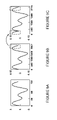
- FIGS. 10A to 10D illustrated are diagrams demonstrating exemplary waveforms corresponding to a system for generating an expanded symbol including a cyclic postfix in accordance with the principles of the present invention of FIG. 8D .
- the DFT length is again 128 samples
- the iDFT length is 2048 transform samples
- the cyclic postfix length is 128 transform samples.
- the time-dependent sampled waveform of FIG. 10A illustrates the original complex-valued symbol, and identifies the end portion 1010 of the waveform that is cyclically reinserted as a prefix.
- FIG. 10B the end portion 1010 of the waveform has been inserted as portion 1020 at the beginning of the waveform before the DFT process (i.e., cyclically rotated symbol before DFT).
- FIG. 10C demonstrates the waveform from FIG. 10B after the DFT and iDFT operation and the result is an up-sampled version thereof (i.e., symbol after iDFT).
- the cyclic prefix 1040 corresponding to the initial portion 1030 of the transformed waveform is inserted at the end of the transformed waveform to form the end portion 1050 of the expanded transformed waveform (i.e., symbol after cyclic postfix insertion).
- the length of the expanded transformed waveform to be transmitted is now 2176 transform samples.
- An advantage of this solution is that it provides a system, subsystem or module to produce mathematically the same result as appending a cyclic prefix, but using a less resource-intensive postfix process.
- latency and buffering are advantageously reduced.
- the result is a transmitted waveform that is the same as that produced by conventional cyclic prefix processing steps, but advantageously requires less processing resources and results in less processing latency.
- the present invention provides an apparatus (e.g., user equipment or a base station) including a modulator configured to map data into complex-valued constellation samples and aggregate the samples into a symbol.
- the apparatus also includes a time pre-rotation module configured to time shift bits of at least one of ending samples of the symbol to a beginning of the symbol to form a time-rotated symbol.
- the apparatus also includes an interpolator configured to construct an up-sampled symbol from the time-rotated symbol.
- the interpolator may include a discrete Fourier transform module configured to map the time-rotated symbol into complex-valued samples in a frequency plane, and an inverse discrete Fourier transform module configured to construct the up-sampled symbol in a time domain from the complex-valued samples.
- the interpolator is configured to apply a phase correction to at least one of samples of the time-rotated symbol, the complex-valued samples and samples of the up-sampled symbol.
- the apparatus still further includes a cyclic postfix module configured to insert a cyclic postfix (e.g., at least one of initial samples of said up-sampled symbol) at an end of the up-sampled symbol to form an expanded up-sampled symbol.
- a length of the cyclic postfix is a function of a ratio of a number of coefficients of an inverse discrete Fourier transform employed by the inverse discrete Fourier transform module to a number of coefficients of a discrete Fourier transform employed by the discrete Fourier transform module and corrected for fractional numbers.
- Program or code segments making up the various embodiments of the present invention may be stored in a computer readable medium or transmitted by a computer data signal embodied in a carrier wave, or a signal modulated by a carrier, over a transmission medium.
- the “computer readable medium” may include any medium that can store or transfer information. Examples of the computer readable medium include an electronic circuit, a semiconductor memory device, a read only memory (“ROM”), a flash memory, an erasable ROM (“EROM”), a floppy diskette, a compact disk (“CD”)-ROM, an optical disk, a hard disk, a fiber optic medium, a radio frequency (“RF”) link, and the like.
- the computer data signal may include any signal that can propagate over a transmission medium such as electronic communication network channels, optical fibers, air, electromagnetic links, RF links, and the like.
- the code segments may be downloaded via computer networks such as the Internet, Intranet, and the like.
- the exemplary embodiment provides both a method and corresponding apparatus consisting of various modules providing functionality for performing the steps of the method.
- the modules may be implemented as hardware (embodied in one or more chips including an integrated circuit such as an application specific integrated circuit), or may be implemented as software or firmware for execution by a computer processor.
- firmware or software the exemplary embodiment can be provided as a computer program product including a computer readable storage structure embodying computer program code (i.e., software or firmware) thereon for execution by the computer processor.
Abstract
Description
Claims (15)
Priority Applications (2)
| Application Number | Priority Date | Filing Date | Title |
|---|---|---|---|
| US12/474,947 US8331468B2 (en) | 2009-05-29 | 2009-05-29 | Apparatus and method for inserting a cyclic postfix for a time-rotated symbol in a communication system |
| PCT/IB2010/001153 WO2010136864A1 (en) | 2009-05-29 | 2010-05-17 | Apparatus and method for inserting a cyclic postfix for a time-rotated symbol in a communication system |
Applications Claiming Priority (1)
| Application Number | Priority Date | Filing Date | Title |
|---|---|---|---|
| US12/474,947 US8331468B2 (en) | 2009-05-29 | 2009-05-29 | Apparatus and method for inserting a cyclic postfix for a time-rotated symbol in a communication system |
Publications (2)
| Publication Number | Publication Date |
|---|---|
| US20100303166A1 US20100303166A1 (en) | 2010-12-02 |
| US8331468B2 true US8331468B2 (en) | 2012-12-11 |
Family
ID=43220199
Family Applications (1)
| Application Number | Title | Priority Date | Filing Date |
|---|---|---|---|
| US12/474,947 Expired - Fee Related US8331468B2 (en) | 2009-05-29 | 2009-05-29 | Apparatus and method for inserting a cyclic postfix for a time-rotated symbol in a communication system |
Country Status (2)
| Country | Link |
|---|---|
| US (1) | US8331468B2 (en) |
| WO (1) | WO2010136864A1 (en) |
Cited By (1)
| Publication number | Priority date | Publication date | Assignee | Title |
|---|---|---|---|---|
| US11290312B2 (en) * | 2013-03-13 | 2022-03-29 | Mitsubishi Electric Corporation | Transmission apparatus that transmits a block signal |
Families Citing this family (5)
| Publication number | Priority date | Publication date | Assignee | Title |
|---|---|---|---|---|
| US20090316804A1 (en) * | 2008-06-20 | 2009-12-24 | Legend Silicon Corp. | Method and apparatus to implement ofdma ranging in wimax system |
| WO2016141994A1 (en) * | 2015-03-12 | 2016-09-15 | Huawei Technologies Co., Ltd. | Preamble for licensed assisted access using fractional ofdm symbol for reduced oob emissions |
| EP3289739B1 (en) * | 2015-04-29 | 2020-08-19 | Indian Institute Of Technology Hyderabad | Method and system for designing a waveform for data communication |
| US10034133B2 (en) | 2015-12-23 | 2018-07-24 | Apple Inc. | Waveform design for Wi-Fi time-of-flight estimation |
| US10461975B2 (en) * | 2016-05-11 | 2019-10-29 | Qualcomm Incorporated | Dynamic cyclic prefix (CP) length in wireless communication |
Citations (12)
| Publication number | Priority date | Publication date | Assignee | Title |
|---|---|---|---|---|
| US6687307B1 (en) * | 2000-02-24 | 2004-02-03 | Cisco Technology, Inc | Low memory and low latency cyclic prefix addition |
| WO2005022794A2 (en) | 2003-08-27 | 2005-03-10 | Sasken Communication Technologies Limited | Combined inverse fast fourier transform and guard interval processing for efficient implementation of ofdm based systems |
| US20050068886A1 (en) * | 2003-09-29 | 2005-03-31 | Xianbin Wang | Multi-symbol encapsulated OFDM transmission |
| US20050276337A1 (en) * | 2004-06-09 | 2005-12-15 | Lucent Technologies, Inc. | Bandwidth efficient orthogonal frequency division multiplexing communication system |
| WO2007123340A2 (en) | 2006-04-20 | 2007-11-01 | Lg Electronics Inc. | Method and apparatus for inserting guard interval in a mobile communication system |
| US20080002645A1 (en) * | 2006-06-28 | 2008-01-03 | Fujitsu Limited | Radio transmission apparatus and method of inserting guard interval |
| WO2008056900A1 (en) | 2006-11-10 | 2008-05-15 | Electronics And Telecommunications Research Institute | Pilot transmitting apparatus and method for sc-fdma system |
| US20080165676A1 (en) | 2006-12-28 | 2008-07-10 | Samsung Electronics Co., Ltd. | Method and apparatus for modulating symbols in an orthogonal frequency division multiplexing system and transmission apparatus using the same |
| US20080222482A1 (en) * | 2007-03-08 | 2008-09-11 | Kabushiki Kaisha Toshiba | Transmitter and receiver |
| US20090074106A1 (en) * | 2007-09-19 | 2009-03-19 | Qualcomm Incorporated | Multi-mode and multi-band transmitters for wireless communication |
| US20090245422A1 (en) * | 2008-03-28 | 2009-10-01 | Qualcomm Incorporated | Method and system for transmit upsampling via ifft |
| US20110096861A1 (en) * | 2005-12-16 | 2011-04-28 | Nokia Corporation | Low complexity method and apparatus to append a cyclic extension to a continuous phase modulation (cpm) signal |
-
2009
- 2009-05-29 US US12/474,947 patent/US8331468B2/en not_active Expired - Fee Related
-
2010
- 2010-05-17 WO PCT/IB2010/001153 patent/WO2010136864A1/en active Application Filing
Patent Citations (13)
| Publication number | Priority date | Publication date | Assignee | Title |
|---|---|---|---|---|
| US6687307B1 (en) * | 2000-02-24 | 2004-02-03 | Cisco Technology, Inc | Low memory and low latency cyclic prefix addition |
| WO2005022794A2 (en) | 2003-08-27 | 2005-03-10 | Sasken Communication Technologies Limited | Combined inverse fast fourier transform and guard interval processing for efficient implementation of ofdm based systems |
| US20050068886A1 (en) * | 2003-09-29 | 2005-03-31 | Xianbin Wang | Multi-symbol encapsulated OFDM transmission |
| US20050276337A1 (en) * | 2004-06-09 | 2005-12-15 | Lucent Technologies, Inc. | Bandwidth efficient orthogonal frequency division multiplexing communication system |
| US20110096861A1 (en) * | 2005-12-16 | 2011-04-28 | Nokia Corporation | Low complexity method and apparatus to append a cyclic extension to a continuous phase modulation (cpm) signal |
| US20090245399A1 (en) * | 2006-04-20 | 2009-10-01 | Jung Hoon Lee | Method and apparatus for inserting guard interval in a mobile communication system |
| WO2007123340A2 (en) | 2006-04-20 | 2007-11-01 | Lg Electronics Inc. | Method and apparatus for inserting guard interval in a mobile communication system |
| US20080002645A1 (en) * | 2006-06-28 | 2008-01-03 | Fujitsu Limited | Radio transmission apparatus and method of inserting guard interval |
| WO2008056900A1 (en) | 2006-11-10 | 2008-05-15 | Electronics And Telecommunications Research Institute | Pilot transmitting apparatus and method for sc-fdma system |
| US20080165676A1 (en) | 2006-12-28 | 2008-07-10 | Samsung Electronics Co., Ltd. | Method and apparatus for modulating symbols in an orthogonal frequency division multiplexing system and transmission apparatus using the same |
| US20080222482A1 (en) * | 2007-03-08 | 2008-09-11 | Kabushiki Kaisha Toshiba | Transmitter and receiver |
| US20090074106A1 (en) * | 2007-09-19 | 2009-03-19 | Qualcomm Incorporated | Multi-mode and multi-band transmitters for wireless communication |
| US20090245422A1 (en) * | 2008-03-28 | 2009-10-01 | Qualcomm Incorporated | Method and system for transmit upsampling via ifft |
Non-Patent Citations (3)
| Title |
|---|
| Dong Li, Penghui Wei and Xiaolong Zhu, "Novel Space-Time Coding and Mapping Scheme in Single-Carrier FDMA Systems", Alcatel Shanghai Bell, China, 2007, IEEE. * |
| Sari, H., et al., "Transmission Techniques for Digital Terrestrial TV Broadcasting," IEEE, Feb. 1995, pp. 100-109. |
| U.S. Appl. No. 12/069,239, filed Feb. 8, 2008, Zielinski, et al. |
Cited By (1)
| Publication number | Priority date | Publication date | Assignee | Title |
|---|---|---|---|---|
| US11290312B2 (en) * | 2013-03-13 | 2022-03-29 | Mitsubishi Electric Corporation | Transmission apparatus that transmits a block signal |
Also Published As
| Publication number | Publication date |
|---|---|
| US20100303166A1 (en) | 2010-12-02 |
| WO2010136864A1 (en) | 2010-12-02 |
Similar Documents
| Publication | Publication Date | Title |
|---|---|---|
| TWI568221B (en) | Method and system for transmission of orthogonal frequency division multiplexed (ofdm) symbols in subframes | |
| US9344953B2 (en) | Apparatus and method for initialization and mapping of reference signals in a communication system | |
| US9350573B2 (en) | Apparatus and method for reducing discontinuities between waveforms in a communication system | |
| JP5156128B2 (en) | Method and apparatus in a wireless communication system | |
| US20170257201A1 (en) | Apparatus and method for transmitting single channel, bonded channel, and mimo ofdm frames with fields to facilitate agc, timing, and channel estimation | |
| CN103281284B (en) | For adjusting the method and the travelling carriage thereof that send timing and send grouping continuously | |
| KR101329193B1 (en) | Apparatus and method for allocation of subcarriers in clustered dft-spread-ofdm | |
| US10211958B2 (en) | Method for transmitting uplink information in multi-user multiple-input multiple-output system, and apparatus | |
| US8331468B2 (en) | Apparatus and method for inserting a cyclic postfix for a time-rotated symbol in a communication system | |
| JP2018517343A (en) | Modem apparatus, communication system, and cyclic prefix processing method | |
| US9628232B2 (en) | Method of and a radio transmission system and radio access equipment for cellular wireless radio transmission | |
| US8396034B2 (en) | Method for determining cell identity in wireless communication system and apparatus therefor | |
| KR101741396B1 (en) | Method for allocating preamble sequence subblock for supporting irregular system bandwidth in wireless communication system and apparatus therefor | |
| KR20160117121A (en) | Method and apparatus for peak to average power reduction in wireless communication systems using spectral mask filling | |
| US11469845B2 (en) | Data transmission method, apparatus, and system | |
| US20140269768A1 (en) | Methods and apparatus for increasing diversity in downlink transmissions | |
| US20120026924A1 (en) | MAC Packet Data Unit Construction for Wireless Systems | |
| Surgiewicz et al. | LTE uplink transmission scheme | |
| Parekha et al. | IEEE 802.11 ac WLAN Simulation in MATLAB. | |
| TW202402006A (en) | Single-carrier frequency-division multiplexing (sc-fdm) for wireless local area networks (wlans) | |
| Dogra et al. | An Enhanced Technique for PAPR Reduction in Mobile WIMAX | |
| CN113574947A (en) | System and method for conjugate data modulation | |
| KR20210055250A (en) | Method and apparatus for estimating phase noise in a wireless communication system |
Legal Events
| Date | Code | Title | Description |
|---|---|---|---|
| AS | Assignment |
Owner name: NOKIA CORPORATION, FINLAND Free format text: ASSIGNMENT OF ASSIGNORS INTEREST;ASSIGNOR:ESCOLAR-PIEDRAS, ALBERTO;REEL/FRAME:022798/0682 Effective date: 20090601 |
|
| STCF | Information on status: patent grant |
Free format text: PATENTED CASE |
|
| FEPP | Fee payment procedure |
Free format text: PAYOR NUMBER ASSIGNED (ORIGINAL EVENT CODE: ASPN); ENTITY STATUS OF PATENT OWNER: LARGE ENTITY Free format text: PAYER NUMBER DE-ASSIGNED (ORIGINAL EVENT CODE: RMPN); ENTITY STATUS OF PATENT OWNER: LARGE ENTITY |
|
| AS | Assignment |
Owner name: NOKIA TECHNOLOGIES OY, FINLAND Free format text: ASSIGNMENT OF ASSIGNORS INTEREST;ASSIGNOR:NOKIA CORPORATION;REEL/FRAME:035445/0496 Effective date: 20150116 |
|
| FPAY | Fee payment |
Year of fee payment: 4 |
|
| AS | Assignment |
Owner name: WSOU INVESTMENTS, LLC, CALIFORNIA Free format text: ASSIGNMENT OF ASSIGNORS INTEREST;ASSIGNOR:NOKIA TECHNOLOGIES OY;REEL/FRAME:045084/0282 Effective date: 20171222 |
|
| FEPP | Fee payment procedure |
Free format text: MAINTENANCE FEE REMINDER MAILED (ORIGINAL EVENT CODE: REM.); ENTITY STATUS OF PATENT OWNER: LARGE ENTITY |
|
| LAPS | Lapse for failure to pay maintenance fees |
Free format text: PATENT EXPIRED FOR FAILURE TO PAY MAINTENANCE FEES (ORIGINAL EVENT CODE: EXP.); ENTITY STATUS OF PATENT OWNER: LARGE ENTITY |
|
| STCH | Information on status: patent discontinuation |
Free format text: PATENT EXPIRED DUE TO NONPAYMENT OF MAINTENANCE FEES UNDER 37 CFR 1.362 |
|
| FP | Lapsed due to failure to pay maintenance fee |
Effective date: 20201211 |
|
| AS | Assignment |
Owner name: OT WSOU TERRIER HOLDINGS, LLC, CALIFORNIA Free format text: SECURITY INTEREST;ASSIGNOR:WSOU INVESTMENTS, LLC;REEL/FRAME:056990/0081 Effective date: 20210528 |