US8332233B2 - Method and system for collecting and analyzing holter data employing a web site - Google Patents
Method and system for collecting and analyzing holter data employing a web site Download PDFInfo
- Publication number
- US8332233B2 US8332233B2 US11/023,263 US2326304A US8332233B2 US 8332233 B2 US8332233 B2 US 8332233B2 US 2326304 A US2326304 A US 2326304A US 8332233 B2 US8332233 B2 US 8332233B2
- Authority
- US
- United States
- Prior art keywords
- analysis
- central server
- ecg data
- user
- data
- Prior art date
- Legal status (The legal status is an assumption and is not a legal conclusion. Google has not performed a legal analysis and makes no representation as to the accuracy of the status listed.)
- Active, expires
Links
Images


Classifications
-
- G—PHYSICS
- G06—COMPUTING; CALCULATING OR COUNTING
- G06Q—INFORMATION AND COMMUNICATION TECHNOLOGY [ICT] SPECIALLY ADAPTED FOR ADMINISTRATIVE, COMMERCIAL, FINANCIAL, MANAGERIAL OR SUPERVISORY PURPOSES; SYSTEMS OR METHODS SPECIALLY ADAPTED FOR ADMINISTRATIVE, COMMERCIAL, FINANCIAL, MANAGERIAL OR SUPERVISORY PURPOSES, NOT OTHERWISE PROVIDED FOR
- G06Q10/00—Administration; Management
- G06Q10/10—Office automation; Time management
-
- G—PHYSICS
- G16—INFORMATION AND COMMUNICATION TECHNOLOGY [ICT] SPECIALLY ADAPTED FOR SPECIFIC APPLICATION FIELDS
- G16H—HEALTHCARE INFORMATICS, i.e. INFORMATION AND COMMUNICATION TECHNOLOGY [ICT] SPECIALLY ADAPTED FOR THE HANDLING OR PROCESSING OF MEDICAL OR HEALTHCARE DATA
- G16H15/00—ICT specially adapted for medical reports, e.g. generation or transmission thereof
-
- G—PHYSICS
- G16—INFORMATION AND COMMUNICATION TECHNOLOGY [ICT] SPECIALLY ADAPTED FOR SPECIFIC APPLICATION FIELDS
- G16H—HEALTHCARE INFORMATICS, i.e. INFORMATION AND COMMUNICATION TECHNOLOGY [ICT] SPECIALLY ADAPTED FOR THE HANDLING OR PROCESSING OF MEDICAL OR HEALTHCARE DATA
- G16H40/00—ICT specially adapted for the management or administration of healthcare resources or facilities; ICT specially adapted for the management or operation of medical equipment or devices
- G16H40/60—ICT specially adapted for the management or administration of healthcare resources or facilities; ICT specially adapted for the management or operation of medical equipment or devices for the operation of medical equipment or devices
- G16H40/67—ICT specially adapted for the management or administration of healthcare resources or facilities; ICT specially adapted for the management or operation of medical equipment or devices for the operation of medical equipment or devices for remote operation
-
- G—PHYSICS
- G16—INFORMATION AND COMMUNICATION TECHNOLOGY [ICT] SPECIALLY ADAPTED FOR SPECIFIC APPLICATION FIELDS
- G16H—HEALTHCARE INFORMATICS, i.e. INFORMATION AND COMMUNICATION TECHNOLOGY [ICT] SPECIALLY ADAPTED FOR THE HANDLING OR PROCESSING OF MEDICAL OR HEALTHCARE DATA
- G16H10/00—ICT specially adapted for the handling or processing of patient-related medical or healthcare data
- G16H10/60—ICT specially adapted for the handling or processing of patient-related medical or healthcare data for patient-specific data, e.g. for electronic patient records
-
- G—PHYSICS
- G16—INFORMATION AND COMMUNICATION TECHNOLOGY [ICT] SPECIALLY ADAPTED FOR SPECIFIC APPLICATION FIELDS
- G16H—HEALTHCARE INFORMATICS, i.e. INFORMATION AND COMMUNICATION TECHNOLOGY [ICT] SPECIALLY ADAPTED FOR THE HANDLING OR PROCESSING OF MEDICAL OR HEALTHCARE DATA
- G16H40/00—ICT specially adapted for the management or administration of healthcare resources or facilities; ICT specially adapted for the management or operation of medical equipment or devices
- G16H40/60—ICT specially adapted for the management or administration of healthcare resources or facilities; ICT specially adapted for the management or operation of medical equipment or devices for the operation of medical equipment or devices
- G16H40/63—ICT specially adapted for the management or administration of healthcare resources or facilities; ICT specially adapted for the management or operation of medical equipment or devices for the operation of medical equipment or devices for local operation
-
- G—PHYSICS
- G16—INFORMATION AND COMMUNICATION TECHNOLOGY [ICT] SPECIALLY ADAPTED FOR SPECIFIC APPLICATION FIELDS
- G16H—HEALTHCARE INFORMATICS, i.e. INFORMATION AND COMMUNICATION TECHNOLOGY [ICT] SPECIALLY ADAPTED FOR THE HANDLING OR PROCESSING OF MEDICAL OR HEALTHCARE DATA
- G16H80/00—ICT specially adapted for facilitating communication between medical practitioners or patients, e.g. for collaborative diagnosis, therapy or health monitoring
Definitions
- the invention relates generally to a system and method for handling medical data on a network.
- the invention includes uploading patient medical data and patient information to a central server for analyzing the patient medical data and preparing a medical report associated with the patient medical data.
- Medical devices such as medical sensors are used both in medical institutions and at home to monitor one or more vital signs or to observe and record patient medical data.
- the medical data is transported to medical personnel who are often specialists and have the expertise to analyze the medical data and to prepare a medical report associated with the medical data.
- the medical personnel use specialized systems, methods, test systems, expert workstations and/or software to aid in the analysis of the patient medical data and in the preparation of a medical report which analyzes the patient medical data.
- the medical data must be readily available to the medical specialists.
- the patient and medical data are located in remote locations away from the location of an available medical specialist.
- One solution is for the medical specialist to travel to the remote location such as a remote medical facility, hospital, or doctor's office to gain access to the patient medical data and to analyze the report.
- the medical data is obtained at the remote facility and shipped via mail or courier service to medical facility or medical specialist located at a remote location.
- these processes are both costly and time consuming and are not desirable when the timely analysis of the patient medical data is critical to providing timely medical care to patients who may have a severe or life threatening condition.
- a system and method of sensing and acquiring patient medical data at a remote location for analysis by a medical specialist who is located at a remote distance would control access to the patient medical data by the medical specialist who performs medical analysis of the patient medical data.
- the medical specialist working at an analysis workstation prepares a medical report associated with the patient medical data. The medical report is selectively provided to the remote location for review and access by local medical personnel or by the patient.
- Such system would provide analysis of the patient medical data using analysis software on the central server.
- the central server stores a medical report based on the analyzed medical data on the central server.
- the medical report is accessible to the patient and/or local medical personnel through the web site.
- the invention is a method of analyzing ECG data of a patient at a site remote from the patient.
- the ECG data is sensed from the patient.
- the sensed ECG data is transferred to a central server over a communication network.
- the transferred ECG data is stored in a data storage area of the central server.
- the stored ECG data is analyzed on the central server using analysis software available via the central server to generate a report on the central server.
- the report is received from the central server.
- the invention is a method for analyzing ECG data of a patient over a network.
- a connection is established between a server and a device having access to the ECG data of the patient.
- the ECG data is stored in a data storage area of the server.
- the stored ECG data is analyzed on the server to generate a report on the server.
- the report related to the analyzed ECG data is transmitted from the server to the device.
- a system permits a user to collect and analyze ECG data of a patient.
- a sensor senses the ECG data from a patient.
- a first interface transfers the sensed ECG data to a computer.
- a second interface transfers the sensed ECG data from the computer to a central server over a communication network so that the ECG data is stored on the central server.
- a third interface for use by the user analyzes the stored ECG data using analysis software available on the central server to generate a report on the central server.
- a fourth interface transfers the report to the computer.
- a system analyzes ECG data of a patient over a network.
- An interface receives ECG data from a source to the central server over a communication network.
- a storage area stores the received ECG data.
- An analysis software analyzes the stored ECG data.
- a processor analyzes the stored ECG data using the analysis software to generate a report on the server.
- the interface also transfers the report from the central server to the source.
- the system and method of the present invention has a number of advantages over the prior art.
- the present system provides for remote acquisition of patient medical data and patient information at a local easily accessible medical facility or possibly at home.
- the patient medical data and patient information is transmitted to a central server that controls the receipt of and access to the patient medical data.
- the patient medical data is analyzed on the central server using the analysis software on the central server. Access to the medical reports are controlled by the central server and provided to the remote computer at the remote location for receipt and review by the local medical provider or the patient.
- Such a system provides a secure, timely and efficient acquisition and analysis of patient medical data that is not provided by prior art systems.
- FIG. 1 is a diagram illustrating a system for analyzing patient medical data over a network according to one embodiment of the invention.
- FIG. 2 is a block diagram illustrating a method of acquiring and controlling the access to and analysis of patient medical data over a network by a central server according to one embodiment of the invention.
- FIG. 3 is a block diagram illustrating the user options menu for initiating the acquisition and analysis of patient medical data over a network according to one embodiment of the invention.
- FIG. 4 is a block diagram illustrating the process of adding a new patient according to one embodiment of the invention.
- FIG. 5 is a block diagram illustrating the patient medical data upload process according to one embodiment of the invention.
- FIG. 6 is a block diagram illustrating the method of transmitting a medical report associated with patient medical data and patient information to the remote computer according to one embodiment of the invention.
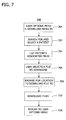
- FIG. 7 is a block diagram illustrating the method of downloading a medical report associated with patient medical data and patient information to the remote computer according to one embodiment of the invention.
- FIG. 8 is a block diagram illustrating a method of analyzing patient medical data using the analysis software on a central server and creating a medical report associated with the patient medical data according to one embodiment of the invention.
- FIG. 9 is a block diagram illustrating users accessing the central server for analyzing patients' medical data for patients according to one embodiment of the invention.
- FIGS. 10A to 10E are exemplary screen displays of the transmission of data from a sensor to the central server.
- FIGS. 12A to 12C are exemplary screen displays of the third interface according to one embodiment of the invention.
- FIGS. 13A to 13B are exemplary screen displays of the fourth interface according to one embodiment of the invention.
- FIG. 1 a block diagram illustrates one preferred embodiment of a system 100 for handling the acquisition and analysis of patient medical data and patient information over a network.
- Patient information is specific data such as name, address, contact information, patient medical history, medical care provider information, medical insurance data, and/or other information associated with a patient 128 .
- Patient medical data is medical data associated with one or more body functions of the patient 128 that have been measured and recorded, such as ECG data, AECG data, Holter data, or the like.
- the system 100 includes a central server 102 with a processor 104 , a storage 106 , and analysis software 124 .
- the processor 104 is configured to associate the patient medical data with the patient information.
- the storage 106 may be any storage system such as local memory, fixed storage disks, remote storage disks, a database, or otherwise configured to store patient medical data, patient information and/or medical reports.
- the analysis software 124 may be medical data analysis software, such as ECG analysis software configured to scan raw ECG data from an ECG recorder and analyze the scanned ECG data.
- a user/technician 132 provides a medical sensor 116 to the patient 128 to record patient medical data.
- the user 132 may be a doctor, a clinician, medical personnel, and/or a technician who are in a doctor's office, a clinic, a hospital, or other location remote from the patient 128 .
- the sensor 116 senses a parameter of the patient's body and stores data corresponding to the sensed parameter as patient medical data.
- the sensor 116 records the patient medical data and stores the patient medical data in a local storage mechanism (not shown) on the sensor 116 .
- This sensor storage mechanism may be local memory or may be a fixed or removable storage medium such as a PCMCIA flashcard.
- the sensor 116 may be a Holter monitor or recorder that records electrocardiogram (ECG) data of the patient 128 over a period of time.
- ECG electrocardiogram
- the user/technician 132 provides to the patient 128 the sensor 116 (e.g., the Holter monitor) which records ECG data or Holter data over a period of 24 hours.
- the Holter monitor is equipped with internal memory for storing the Holter data (not shown). After completing the recording of the patient medical data, the patient 128 returns the sensor 116 to the user 132 .
- the sensor 116 is also equipped with a communication interface configured to download or transmit the stored patient medical data from the sensor 116 to a remote computer 112 , which is remote with respect to the central server 102 .
- the user 132 downloads the sensed patient medical data to the central server 102 via an interface; for example, the sensor 116 may have a Universal Serial Bus (USB) interface 118 that is commonly found on a personal computer.
- the remote computer 112 includes a USB port 119 such that the sensor 116 transfers the patient medical data via its USB interface 118 through the USB port 119 of the remote computer 112 to the central server 102 via a second interface 108 .
- the patient medical data is transmitted from the sensor 116 to the central server 102 .
- the interface 118 may be any type for transferring data from the sensor 116 to the remote computer 102 , such as a serial interface, a parallel interface, a local area network interface, an infrared link, an optical interface, or other hard-wired or wireless interface.
- the senor 116 may also include a removable storage medium or mechanism for storage of the patient medical data.
- a removable storage medium is a PCMCIA flash card.
- the sensor 116 and the remote computer 112 would each be configured for the PCMCIA card. Initially, the card would be positioned within the sensor 116 to store patient data being recorded by the sensor 116 . After recording and storage are completed, the PCMCIA flashcard with the stored patient medical data from the sensor 116 is removed from the sensor 116 and inserted into the PCMCIA slot of the remote computer 112 . The patient medical data is removed, copied, or transferred by the remote computer 112 to its memory for segmentation and compression.
- the PCMCIA card may itself be equipped with the USB interface, in which case the patient medical data is transferred from the PCMCIA card via the USB interface to the remote computer 112 .
- Other memory storage devices are also possible.
- the sensor 116 and the remote computer 112 may be configured to store and retrieve patient medical data using a floppy disk, a CD-ROM, a memory stick, memory card, or other removable storage medium.
- FIGS. 10A to 10E illustrate exemplary screen displays of a user interface illustrating the transmission of data from a sensor to the central server 102 .
- FIG. 10A shows a screenshot of a log-in screen.
- the user 132 at the remote computer 112 uses logs on to the MyHolter.com via a browser.
- the user 132 operates software (e.g., Citrix client application) to logon to the MyHolter.com, by first logging on to the central server (e.g., Citrix® server).
- the central server e.g., Citrix® server
- FIG. 10B shows a screenshot providing the user 132 with options for transferring the patient medical data.
- the user 132 has options such as “Start Scan”, “Configuration”, “Patient Files” and “Exit”.
- FIG. 10C shows the user 132 has various options in transferring the sensed patient medical data (e.g., ECG data) from the sensor 116 to the central server.
- FIG. 10D illustrates that the user 132 is presented to enter information about the patient 128 .
- the user 132 is further provided with options in FIG. 10E before transferring the sensed patient medical data from the sensor 116 to the central server 102 .
- the user 132 may provide sensor 116 types (e.g., “Holter Record Type”), “Digital Drive”, and/or other settings before commencing the transfer.
- FIGS. 10A to 10E illustrate exemplary screen displays of the transmission of data from the sensor 116 to the central server 102 on a display 114 of the remote computer 112 .
- Other display layouts and/or configurations of the options/functions discussed above may be employed.
- other display layouts and/or configurations of screen displays e.g., FIGS. 11A to 11C , 12 A to 12 C, and 13 A and 13 B) may be employed.
- the user 132 after receiving the patient medical data from the sensor 116 , the user 132 stores the received patient medical data on the local storage medium (not shown) of the computer 112 .
- the user 132 may segment the patient medical data and/or compress the segmented patient medical data for improved transmission to the central server 102 .
- patient medical data are usually large data files of more than 10 megabytes of data.
- the remote computer 112 may be used to optionally compress the patient medical data into a plurality of smaller files such as one-megabyte files.
- the plurality of one-megabyte files composing a single patient medical data are identified or named in such a manner as to enable their efficient and effective decompression back into the original patient medical data.
- this optional transmission of the smaller segmented and/or compressed data files improves patient medical data transmission since a transmission error occurring during the transmission will only require the retransmission of a single one-megabyte files, rather than the entire patient medical data file.
- the user 132 transmits the patient medical data on the remote computer 112 through the second interface 108 to the storage 106 on the central server 102 .
- the communication network 108 connecting the remote computer 112 and the central server 102 may be any communication network capable of transmission of data, such as a public switched network, a public data network, a packet switched data network, an Internet, or a wireless network.
- the communication network may be the Internet capable of supporting web pages and web page communications.
- the remote computer 112 may be equipped with an Internet communication interface or service from an Internet Service Provider (ISP) who enables communication of data between the remote computer 112 and any other interconnected computer including the central server 102 .
- ISP Internet Service Provider
- the second interface 108 is part of software (e.g., Citrix® ICA client) installed in the remote computer 112 that maps the sensor 116 to a particular data storage area of the storage 106 on the central server 102 (e.g., Citrix® server).
- the central server 102 recognizes the sensor 116 as another data storage or memory device via the USB port 119 and the second interface 108 when the sensor 116 is connected to the computer 112 via the USB port 119 .
- the second interface 108 permits a direct transmission of the patient medical data from the sensor 116 via the USB port 119 to the central server 102 .
- the second interface 108 next assigns a particular storage area of the storage 106 on the central server 102 for storing the patient medical data received from the sensor 116 . With such recognition, the second interface 108 assists in ensuring that the patient medical data of a patient is not commingled with other patient medical data of another patient on the storage 106 on the central server 102 .
- FIGS. 11A to 11C illustrate exemplary screen displays of the second interface 108 .
- FIG. 11A illustrates that the user 132 has an option of decompress the sensed patient medical data (e.g., ECG data) only or decompress and scan the sensed patient medical data when transferring to the central server 102 .
- FIG. 11B shows an exemplary display of progress indicator showing transferring/copying of the sensed patient medical data from the sensor 116 to the central server 102 .
- FIG. 11C shows an exemplary display of decompressing progress indicator of the patient medical data in the computer 112 .
- the second interface 108 also includes a web site comprising one or more web pages hosted by the central server 102 which is configured to receive data from and transmit data to the remote computer 112 .
- the remote computer 112 includes an Internet browser or a Citrix® client application for sending the patient medical data from the remote computer 112 to the central server 102 .
- FIGS. 11A to 11C may be employed when a web site is used.
- the processor 104 of the central server 102 hosts a web site including web pages such that the remote computer 112 located remotely from the central server 102 can access the web pages.
- the user 132 at the remote computer 112 transmits the patient medical data and associated patient information from its memory to the central server 102 through the web pages.
- These web pages acting as the second interface 108 permit the processor 104 to receive the segmented and compressed patient medical data and associated patient information received from remote computer 112 .
- the processor 104 decompresses the patient medical data and recompiles the segmented patient medical data and stores the patient medical data and patient information on the storage 106 on the central server 102 .
- a remote server (not shown) connected to the communication network between the remote computer 112 and the central server 102 may be employed.
- the remote server hosts the web page that is accessible by the remote computer 112 configured with a web browser.
- the remote computer 112 transmits the patient medical data and patient information to the web page of the remote server.
- the remote server transfers the received patient medical data and patient information to the central server 102 over the communication network to the second interface 108 .
- This optional configuration allows more flexibility.
- the remote server may be hosted by an Internet Service Provider (ISP) at a central communication hub in the communication network and the central server 102 may be remotely located at a medical institution or medical service provider's location.
- ISP Internet Service Provider
- the central server 102 may receive patient medical data from a plurality of sensor 116 and/or remote computers 112 over the communication (to be discussed in detail in FIG. 9 ). While FIG. 1 only shows a single sensor 116 and a single remote computer 112 , in operation a plurality of sensors would provide patient medical data to each remote computer 112 . Additionally, a plurality of remote computers 112 may be located at a plurality of widely dispersed medical institutions, all of which are independently connected to the communication network. As such, the plurality of remote computers 112 and the central server 102 communicate over the communication network via the second interface 108 using a secure access that is a minimum of 128-bit secure socket layer connection. In other embodiments, other secure access arrangements may also be incorporated consistent with the invention.
- the user 132 uses a third interface 110 to access the analysis software 124 on the central server 102 to analyze the stored patient medical data and/or patient information stored on the central server 102 .
- the third interface 110 may be a series of web pages of a web site (e.g., myHolter.com) hosted by the central server 102 that present a list of options, such as those shown in a user options menu 304 in FIG. 3 .
- the third interface 110 may be part of software (e.g., Citrix® client) installed in the remote computer 112 that has options in analyzing the stored patient medical data on the central server 102 .
- the processor 104 is configured to use analysis software 124 on the central server 102 to analyze the stored patient medical data.
- the analysis software 124 provides tools/functions to analyze the stored patient medical data, such as the QT interval, PR interval, or the like of a patient's ECG data.
- FIGS. 12A to 12C illustrate exemplary screen displays of the third interface 110 .
- FIG. 12A shows an example of various analysis setup parameters (define calibration beat 1204 , define normal beat 1206 , create beat template 1208 , paced beats only analysis 1210 , ST analysis, QT analysis, inverted or uninverted) that the user 132 has in using the analysis software 124 .
- FIG. 12A shows the user 132 has an option of different tabs of the patient medical data (e.g., “Analysis Setup”, “12 Lead View”, or “Analysis Option”.)
- the user 132 has a list of settings on the right side of FIG. 12A (e.g., ST Analysis, QT Analysis, inverted or the like).
- button 1202 is an “Exit” function which allows the user 132 to exit the program (e.g., MyHolter.com) and the analysis.
- Button 1204 is a “Find a Better Calibration Beat” function that allows the user 132 to search the data at the beginning of the scan for a better, more consistent calibration pulse.
- Button 1206 is a “Find Another Normal Beat” function that searches further in the data for a better, more representative normal beat.
- Button 1208 is a “Create a New Template from the Current Beat” function that allows the user to specifically template any odd or unique morphology.
- Button 1210 is a “Paced Beats Only Analysis” function which may be used if the user/technician 132 expects the data is from a pacer-only patient.
- Button 1212 is a “Start Analysis” function that launches the user into the analysis depicted by the progress bar in FIG. 12C .
- FIG. 12B shows a screenshot of the “Analysis Options” in which the user 132 can determine different analysis options (e.g., ST Depression Limit, ST Elevation Limit, Minimum Pause Limit, Tachycardia Rate, Bradycardia Rate, Supraventricular Tachycardia (SVT) Minimum Rate, Supraventricular Ectopic (SVE) Minimum Rate, Supraventricular Ectopic (SVE) Prematurity, or the like) before analyzing the patient medical data.
- different analysis options e.g., ST Depression Limit, ST Elevation Limit, Minimum Pause Limit, Tachycardia Rate, Bradycardia Rate, Supraventricular Tachycardia (SVT) Minimum Rate, Supraventricular Ectopic (SVE) Minimum
- the analysis of the patient medical data may not occur immediately after the patient medical data is stored on the storage 106 of the central serve 102 .
- the user 132 may store unanalyzed patient medical data on the central server 102 for later analysis. In one embodiment, there may be a storage limit of unanalyzed patient medical data on the storage 106 of the central server 102 .
- the user 132 transmits the medical report from the central server 102 to the remote computer 112 which displays the medical report on the display 114 , stores the medical report on a local storage medium (not shown), or prints the report on a local printer (not shown) associated with the remote computer 112 .
- FIG. 2 illustrates one process for analyzing patient information, patient medical data, and medical reports by the central server 102 .
- the user 132 logs onto the central server 102 at 302 .
- the central server 102 may receive patient information at 400 from the logged on user 132 or receive patient medical data at 500 .
- the central server 102 associates the received patient medical data with patient information at 202 .
- the patient information may be pre-existing patient information or new patient information added via 400 .
- the user 132 stores each patient medical data in a particular part of the storage 106 of the central server 102 .
- the central server 102 makes the patient medical data available for analysis using the analysis software 124 .
- the user 132 at 206 uses the analysis software to analyze the patient medical data on the central server 102 .
- the central server 102 may restrict access to a particular patient medical data file.
- the analysis software 124 After analyzing the stored patient medical data at 206 , the analysis software 124 generates a medical report at 208 .
- the central server 102 also stores the medical report on the storage 106 at 208 and associates it with the corresponding patient medical data and the patient information at 210 . Once the medical report is associated with the patient information, the medical report is made available to one or more users 132 at computers 112 based on pre-established authorization and notification assignments (e.g., user logins) at 212 . The user 132 may request one of the stored medical reports at 606 using the “review results” process discussed later in FIG. 6 . If the user selects to review the medical report at 606 , the central server 102 transmits the medical report at 214 to the computer 112 associated with the requesting user 132 over the first network 110 .
- the medical data of the patient 128 is recorded at the site of the patient 128 with the sensor 116 .
- a local medical care provider such as a physician at a local medical office provides the patient 128 with the sensor 116 .
- the patient 128 uses the sensor 116 such as an electrocardiogram (ECG) data recorder or the Holter monitor/recorder to record ECG data over a defined period of time (e.g., 24 hours).
- ECG electrocardiogram
- the patient 128 wears the monitor at home or work during normal daily activity.
- the patient 128 returns to the medical office or facility with the sensor 116 or directly accesses a remote computer 112 and the necessary acquisition software as discussed above and below.
- the sensor 116 has the patient medical data stored internally in memory or on a removable storage format.
- the user 132 of the remote computer 112 is a medical technician, medical assistant, doctor, or may be the patient 128 .
- the remote computer 112 is configured with software designed to retrieve and manage the patient medical data.
- a software configuration consistent with this invention is the patient medical data acquisition, and program for transmitting patient medical data from the sensor 116 to the central server 102 .
- a software process may also comprise storing the patient medical data on the remote computer 112 , compressing the medical data, and transferring the patient medical data from the remote computer 112 to the central server 102 .
- connection between the sensor 116 and the remote computer 112 is configured such that the central server 102 may operate the sensor 116 as a removable drive for transferring the patient medical data.
- the remote computer 112 is configured such that the storage format and patient medical data as presented is seen as a removable drive on the remote computer 112 .
- the remote computer 112 is configured with the web browser or other data communication interface (e.g., Citrix® client application), such as a second interface 108 .
- the user 132 of the remote computer 112 logs onto the central server 102 through a secure access connection such as a secure socket layer connection with a 128-bit minimum encryption. This provides secure access to the central server 102 and the transmitted patient medical data and the patient information.
- the central server 102 e.g., a Citrix® server
- the central server 102 also authenticates the Citrix® client application in the remote computer 112 , as seen in FIG. 10B .
- the central server 102 hosts a web page and receives the patient medical data via the web page from the remote computer 112 configured with the web browser.
- the central server 102 stores the received patient medical data and patient information on the storage 106 .
- the user 132 via the third interface 110 uses the analysis software 124 on the central server to analyze the stored patient medical data.
- the analysis software 124 generates the medical report associated with the patient medical data and stores the medical report on the central server 102 .
- the central server 102 associates the medical report with the patient information and patient medical data and provides selective access to the medical report from one or more computers 112 or users 132 of computers 112 .
- the central server 102 transmits or provides access to the medical report by the remote computer 112 via the fourth interface 120 .
- FIG. 3 illustrates the user login screen 302 that is presented to the user 132 of the remote computer 112 when the user 132 logs into the central server 102 .
- the user 132 is presented with a user options menu 304 .
- the list of available options for user 132 are defined by the central server 102 based on a pre-establish list of authorized functions or activities based on the user identification number.
- a medical assistant 132 in a medical office may operate the remote computer 112 to upload patient medical data.
- the medical assistant user 132 may not be authorized to view the associated medical reports once completed. However, the attending physician may be notified of the availability of the medical report, and may access the system to view the medical report.
- the user 132 may select one of the options from the “users option menu”: (1) add new patient, (2) upload patient medical data, (3) review a medical report, (4) download a medical report, (5) analyze files, or (6) log off.
- FIGS. 4 to 8 illustrate processes associated with each of these user options respectively.
- FIG. 4 illustrates the “add new patient” process 400 as selected by the user 132 on the “user options menu” 304 , the user is prompted to supply the patient information at 402 .
- the central server 102 presents the user 132 with a series of user information screens.
- the user 132 interacts with the web page hosted by the central server 102 or optional remote server 130 and enters the patient information.
- the user 132 is then requested to save or cancel the entered data at 404 . If the user 132 selects to cancel, the user 132 is returned at 406 to the user options menu 304 . If the user 132 selects to save, the central server 102 verifies the validity of the data format at 406 .
- the user 132 is returned to the patient entry at 416 . If the data is valid, the central server 102 parses the patient information into a save format at 408 and adds the patient information to a database at 410 . The method further adds a log number to the patient information at 412 when the information is stored and sends a confirmation message at 414 to the user 132 . Once this is complete, the central server 102 returns the user 132 at 416 to the user options menu 304 . The user 132 need only complete the “add new patient” process of 400 for a patient 128 that is new to the central server 102 . If the patient information already exists in the central server 102 for a patient 128 , this process is not required. At this point, the user 132 may upload the patient medical data, such as the Holter data to the central server 102 from the computer 112 .
- the central server 102 parses the patient information into a save format at 408 and adds the patient information to a database at 410 . The method further adds a
- the user 132 of the remote computer 112 selects the “upload files” process 500 from the user options menu 304 , the user 132 is prompted to select either a new or existing patient 128 at 502 . If a new patient 128 , the user 132 is directed to the new patient sequence 400 as discussed above. If an existing patient 128 , the user 132 is offered a list of patients at 504 . Of course, the list of patients offered to a particular user 132 by the central server 102 is limited based on the user authorization identified when the user 132 logged into central server 201 .
- the sensor 116 or the remote computer 112 uploads the patient medical data to the central server 102 at 506 and the central server 102 receives the uploaded files.
- the transmission of the patient medical data from sensor 116 or the remote computer 112 to the central server 102 may occur immediately or may be delayed to a later time. For instance, the transmission of the patient medical data may be delayed to be sent after business hours, when the need or usage of the remote computer 112 or first network 110 is less.
- the central server 102 decompresses the received compressed patient medical data and recompiles the patient medical data to the state it was before being compressed by the remote computer 112 .
- the central server 102 associates the patient medical data with the patient information and stores the patient medical data in storage 106 , as discussed above and shown at 508 .
- the central server 102 is notified of new patient medical data at 510 and a confirmation message is sent to the user 132 at the remote computer 112 at 512 .
- the user 132 operating the remote computer 112 is returned to the user options menu 304 at 416 .
- the user 132 of the remote computer 112 searches for a particular medical report associated with a particular patient 128 and selects the patient 128 or the medical report at 602 .
- the central server 102 provides the remote computer 112 with a list of available completed medical reports and associated files at 604 .
- the user 132 selects one of the available medical reports to view at 606 .
- the user 132 may add notes to the medical report or to an associated report or file at 608 .
- the user 132 may choose to view another medical report or return to the user options menu 304 at 416 .
- the user 132 searches for a particular patient 128 at 702 .
- the central server 102 lists the patients 128 available to the user 132 and the associated files at 704 . From the list presented by the central server 102 , the user 132 selects a file to download at 706 .
- the user 132 selects a memory or storage location associated with the remote computer 112 to download the file to at 708 and initiates the download process.
- the central server 102 downloads the selected file via the first communication interface 108 over the first network 110 to the remote computer 112 at 710 . Once the download has been complete, the central server 102 returns the user 132 at 416 to the user options menu 304 .
- the user 132 instructs analysis software 124 to analyze the patient medical data. It is understood that the user 132 may only analyze or may only have access to the patient medical data or data files that are associated with the login parameter/permission of the user 132 at 302 in FIG. 3 .
- the user 132 scans the stored patient medical data using the analysis software 124 on the central server 102 at 806 .
- the user 132 is presented with an option of performing the analysis immediately or storing the patient medical data without analysis. If the user 132 chooses to analyze the patient medical data at a later time, the unanalyzed data is stored in the storage 106 at 810 .
- the storage for unanalyzed patient medical data may be limited.
- the analysis software 124 analyzes the stored patient medical data at 814 .
- the patient medical data may be Holter data from a Holter monitor and the analysis software 124 may be a Holter program to perform a Holter analysis of the Holter data.
- the Holter analysis of the medical report includes one or more data files including a Portable Document File (PDF) file containing the Holter analysis report.
- PDF Portable Document File
- the central server 102 stores the medical report on storage 106 .
- the central server 102 makes the medical report (e.g., Holter report) available to the user 132 for viewing or printing.
- the medical report may be in a PDF file format, which is absorbed into the storage 106 as an object.
- Other associated files may be included in the database or stored in other storage 106 controlled by the processor 104 .
- the central server 102 When the central server 102 receives the medical report, the central server 102 notifies the associated or designated remote computer 112 that the medical report is complete and available for access and review.
- the remote computer 112 receives the notification and is provided access to the medical report. Controlled access by the central server 102 to the medical report is made in several different ways including viewing the report in a view mode from the remote computer 112 equipped with a web browser. Another method is for the remote computer 112 equipped with PDF-format reader, to view the document.
- the remote computer 112 displays the PDF-formatted medical report on display 114 , stores the medical report locally, or prints the medical report on an associated printer (not shown).
- the medical report is transmitted as an electronic file by the central server 102 to the remote computer 112 via the first communication interface 108 over the first network 110 .
- FIG. 9 is a block diagram illustrating a plurality of users at sites 910 accessing the central server 902 for analyzing patients' medical data for patients according to one form of the invention.
- a site 910 - 1 is a location, such as a doctor's office, a clinician's office, a hospital, or a patient's home where a patient's medical data (e.g., Holter data) may be collected by a workstation at the site 910 - 1 .
- a site 910 -X is also another location where another patient's medical data is gathered and acquired. It is to be understood that there may be a number of site 910 where the patient medical data is gathered and received.
- a Holter data acquisition/playback device e.g., sensor 116 in FIG. 1
- a printer e.g., a printer
- a workstation e.g., a printer
- FIG. 9 a Holter data acquisition/playback device
- the patient 128 , the sensor 116 , the user/technician 132 , the remote computer 112 and the display 114 in FIG. 1 are located at site 910 .
- a playback device (e.g., the sensor 116 in FIG. 1 ) transfers the patient medical data to the central server 102 or to a workstation 914 - 1 (e.g., remote computer 112 in FIG. 1 ).
- the user 132 logs onto a web site (e.g., myHolter.com) hosted by the central server 902 or logs onto the central server 902 via an application installed in the workstation 914 - 1 (e.g., Citrix® client).
- a firewall 912 - 1 assists in ensuring a secure access/session while the user 132 is logged on.
- the patient medical data is transferred from the playback device (e.g., the sensor 116 in FIG.
- the central server 902 is configured to assign a site-specific instance of an online Holter program and a unique server storage location for site 01 .
- another user at site X will access a specific instance of an online Holter program and a unique server storage location assigned for the site X.
- the central server 102 further assists in ensuring a secure access of a uniquely assigned storage area on the central server 102 .
- the invention is also a method for managing the receipt and analysis of Holter monitor patient medical data received at the remote computer 112 and analyzed the patient medical data on the central server 102 by using the analysis software 124 on the central server 102 .
- patient medical data is recorded on the sensor 116 and is stored on a local storage medium.
- the patient medical data is transmitted to the remote computer 112 .
- new patient information is created that corresponds to the patient medical data.
- the patient medical data is received from the sensor 116 and stored on the remote computer 112 .
- the remote computer 112 segments and/or compresses the patient medical data and transmits the segmented and/or compressed patient medical data and corresponding patient information to the central server 102 .
- the central server 102 receives the segmented and/or compressed patient medical data and corresponding patient information.
- the central server 102 decompresses and/or compiles the patient medical data and stores the patient medical data and patient information in storage 106 .
- a processor 104 associated with the central server 102 controls the access to the patient medical data and patient information.
- the user 132 analyzes the patient medical data using the analysis software 124 on the central server 102 . Based on this analysis, the central server 102 generates the medical report and stores the medical report.
- Processor 104 controls access to the medical report.
- the central server 102 transmits the medical report to the remote computer 112 .
- the remote computer 112 receives the medical report from the central server 102 and displays the medical report.
Abstract
Description
Claims (39)
Priority Applications (1)
| Application Number | Priority Date | Filing Date | Title |
|---|---|---|---|
| US11/023,263 US8332233B2 (en) | 2002-11-13 | 2004-12-27 | Method and system for collecting and analyzing holter data employing a web site |
Applications Claiming Priority (3)
| Application Number | Priority Date | Filing Date | Title |
|---|---|---|---|
| US10/294,541 US7353179B2 (en) | 2002-11-13 | 2002-11-13 | System and method for handling the acquisition and analysis of medical data over a network |
| US61415404P | 2004-09-29 | 2004-09-29 | |
| US11/023,263 US8332233B2 (en) | 2002-11-13 | 2004-12-27 | Method and system for collecting and analyzing holter data employing a web site |
Related Parent Applications (1)
| Application Number | Title | Priority Date | Filing Date |
|---|---|---|---|
| US10/294,541 Continuation-In-Part US7353179B2 (en) | 2002-11-13 | 2002-11-13 | System and method for handling the acquisition and analysis of medical data over a network |
Publications (2)
| Publication Number | Publication Date |
|---|---|
| US20050108055A1 US20050108055A1 (en) | 2005-05-19 |
| US8332233B2 true US8332233B2 (en) | 2012-12-11 |
Family
ID=34576291
Family Applications (1)
| Application Number | Title | Priority Date | Filing Date |
|---|---|---|---|
| US11/023,263 Active 2027-01-30 US8332233B2 (en) | 2002-11-13 | 2004-12-27 | Method and system for collecting and analyzing holter data employing a web site |
Country Status (1)
| Country | Link |
|---|---|
| US (1) | US8332233B2 (en) |
Cited By (18)
| Publication number | Priority date | Publication date | Assignee | Title |
|---|---|---|---|---|
| US9220430B2 (en) | 2013-01-07 | 2015-12-29 | Alivecor, Inc. | Methods and systems for electrode placement |
| US9247911B2 (en) | 2013-07-10 | 2016-02-02 | Alivecor, Inc. | Devices and methods for real-time denoising of electrocardiograms |
| US9254092B2 (en) | 2013-03-15 | 2016-02-09 | Alivecor, Inc. | Systems and methods for processing and analyzing medical data |
| US9254095B2 (en) | 2012-11-08 | 2016-02-09 | Alivecor | Electrocardiogram signal detection |
| US9351654B2 (en) | 2010-06-08 | 2016-05-31 | Alivecor, Inc. | Two electrode apparatus and methods for twelve lead ECG |
| US9420956B2 (en) | 2013-12-12 | 2016-08-23 | Alivecor, Inc. | Methods and systems for arrhythmia tracking and scoring |
| US9649042B2 (en) | 2010-06-08 | 2017-05-16 | Alivecor, Inc. | Heart monitoring system usable with a smartphone or computer |
| US9839363B2 (en) | 2015-05-13 | 2017-12-12 | Alivecor, Inc. | Discordance monitoring |
| US10127357B2 (en) | 2015-05-18 | 2018-11-13 | Zoll Medical Corporation | Mobile monitoring and patient management system |
| US10155118B2 (en) | 2013-08-01 | 2018-12-18 | Zoll Medical Corporation | Systems and methods for utilizing identification devices in a wearable medical therapy device |
| US10610624B2 (en) | 2013-03-14 | 2020-04-07 | Smith & Nephew, Inc. | Reduced pressure therapy blockage detection |
| US10639502B2 (en) | 2010-10-12 | 2020-05-05 | Smith & Nephew, Inc. | Medical device |
| US11315681B2 (en) | 2015-10-07 | 2022-04-26 | Smith & Nephew, Inc. | Reduced pressure therapy device operation and authorization monitoring |
| US11369730B2 (en) | 2016-09-29 | 2022-06-28 | Smith & Nephew, Inc. | Construction and protection of components in negative pressure wound therapy systems |
| US11602461B2 (en) | 2016-05-13 | 2023-03-14 | Smith & Nephew, Inc. | Automatic wound coupling detection in negative pressure wound therapy systems |
| US11633112B2 (en) | 2021-03-08 | 2023-04-25 | Medtronic, Inc. | Automatic alert control for acute health event |
| US11712508B2 (en) | 2017-07-10 | 2023-08-01 | Smith & Nephew, Inc. | Systems and methods for directly interacting with communications module of wound therapy apparatus |
| US11793924B2 (en) | 2018-12-19 | 2023-10-24 | T.J.Smith And Nephew, Limited | Systems and methods for delivering prescribed wound therapy |
Families Citing this family (63)
| Publication number | Priority date | Publication date | Assignee | Title |
|---|---|---|---|---|
| US8165893B1 (en) * | 2005-02-16 | 2012-04-24 | Ideal Life Inc. | Medical monitoring and coordinated care system |
| US8171418B2 (en) * | 2007-01-31 | 2012-05-01 | Salesforce.Com, Inc. | Method and system for presenting a visual representation of the portion of the sets of data that a query is expected to return |
| JP2009053661A (en) * | 2007-07-30 | 2009-03-12 | Fujifilm Corp | Radiation detecting cassette and medical system |
| EP2022393A3 (en) * | 2007-07-30 | 2011-03-02 | FUJIFILM Corporation | Radiation detecting cassette and medical system |
| US8781530B2 (en) * | 2008-12-16 | 2014-07-15 | At&T Intellectual Property I, L.P. | OTA file upload servers |
| US8856188B2 (en) * | 2009-03-13 | 2014-10-07 | Bruce Reiner | Electronic linkage of associated data within the electronic medical record |
| US9066664B2 (en) | 2009-03-13 | 2015-06-30 | Polar Electro Oy | Data transfer |
| GB0905377D0 (en) * | 2009-03-30 | 2009-05-13 | Danmedical Ltd | Medical apparatus |
| US20110306894A1 (en) * | 2010-06-14 | 2011-12-15 | Spaulding Randol R | Systems, methods and apparatus for acquiring and managing patient/subject data |
| US20120089000A1 (en) | 2010-10-08 | 2012-04-12 | Jon Mikalson Bishay | Ambulatory Electrocardiographic Monitor For Providing Ease Of Use In Women And Method Of Use |
| US8239012B2 (en) | 2010-10-08 | 2012-08-07 | Cardiac Science Corporation | Microcontrolled electrocardiographic monitoring circuit with differential voltage encoding |
| US9037477B2 (en) | 2010-10-08 | 2015-05-19 | Cardiac Science Corporation | Computer-implemented system and method for evaluating ambulatory electrocardiographic monitoring of cardiac rhythm disorders |
| US20120089417A1 (en) * | 2010-10-08 | 2012-04-12 | Bardy Gust H | Computer-Implemented System And Method For Mediating Patient-Initiated Physiological Monitoring |
| US8613708B2 (en) | 2010-10-08 | 2013-12-24 | Cardiac Science Corporation | Ambulatory electrocardiographic monitor with jumpered sensing electrode |
| US10463269B2 (en) | 2013-09-25 | 2019-11-05 | Bardy Diagnostics, Inc. | System and method for machine-learning-based atrial fibrillation detection |
| US10736531B2 (en) | 2013-09-25 | 2020-08-11 | Bardy Diagnostics, Inc. | Subcutaneous insertable cardiac monitor optimized for long term, low amplitude electrocardiographic data collection |
| US10806360B2 (en) | 2013-09-25 | 2020-10-20 | Bardy Diagnostics, Inc. | Extended wear ambulatory electrocardiography and physiological sensor monitor |
| US10820801B2 (en) | 2013-09-25 | 2020-11-03 | Bardy Diagnostics, Inc. | Electrocardiography monitor configured for self-optimizing ECG data compression |
| US10736529B2 (en) | 2013-09-25 | 2020-08-11 | Bardy Diagnostics, Inc. | Subcutaneous insertable electrocardiography monitor |
| US9504423B1 (en) | 2015-10-05 | 2016-11-29 | Bardy Diagnostics, Inc. | Method for addressing medical conditions through a wearable health monitor with the aid of a digital computer |
| US9364155B2 (en) | 2013-09-25 | 2016-06-14 | Bardy Diagnostics, Inc. | Self-contained personal air flow sensing monitor |
| US10165946B2 (en) | 2013-09-25 | 2019-01-01 | Bardy Diagnostics, Inc. | Computer-implemented system and method for providing a personal mobile device-triggered medical intervention |
| US9730593B2 (en) | 2013-09-25 | 2017-08-15 | Bardy Diagnostics, Inc. | Extended wear ambulatory electrocardiography and physiological sensor monitor |
| US10667711B1 (en) | 2013-09-25 | 2020-06-02 | Bardy Diagnostics, Inc. | Contact-activated extended wear electrocardiography and physiological sensor monitor recorder |
| US9717432B2 (en) | 2013-09-25 | 2017-08-01 | Bardy Diagnostics, Inc. | Extended wear electrocardiography patch using interlaced wire electrodes |
| US9433367B2 (en) | 2013-09-25 | 2016-09-06 | Bardy Diagnostics, Inc. | Remote interfacing of extended wear electrocardiography and physiological sensor monitor |
| US9615763B2 (en) | 2013-09-25 | 2017-04-11 | Bardy Diagnostics, Inc. | Ambulatory electrocardiography monitor recorder optimized for capturing low amplitude cardiac action potential propagation |
| US10433748B2 (en) | 2013-09-25 | 2019-10-08 | Bardy Diagnostics, Inc. | Extended wear electrocardiography and physiological sensor monitor |
| US11213237B2 (en) | 2013-09-25 | 2022-01-04 | Bardy Diagnostics, Inc. | System and method for secure cloud-based physiological data processing and delivery |
| US9433380B1 (en) | 2013-09-25 | 2016-09-06 | Bardy Diagnostics, Inc. | Extended wear electrocardiography patch |
| US9775536B2 (en) | 2013-09-25 | 2017-10-03 | Bardy Diagnostics, Inc. | Method for constructing a stress-pliant physiological electrode assembly |
| US9737224B2 (en) | 2013-09-25 | 2017-08-22 | Bardy Diagnostics, Inc. | Event alerting through actigraphy embedded within electrocardiographic data |
| US10888239B2 (en) | 2013-09-25 | 2021-01-12 | Bardy Diagnostics, Inc. | Remote interfacing electrocardiography patch |
| US10624551B2 (en) | 2013-09-25 | 2020-04-21 | Bardy Diagnostics, Inc. | Insertable cardiac monitor for use in performing long term electrocardiographic monitoring |
| US9717433B2 (en) | 2013-09-25 | 2017-08-01 | Bardy Diagnostics, Inc. | Ambulatory electrocardiography monitoring patch optimized for capturing low amplitude cardiac action potential propagation |
| US9655538B2 (en) | 2013-09-25 | 2017-05-23 | Bardy Diagnostics, Inc. | Self-authenticating electrocardiography monitoring circuit |
| US10799137B2 (en) | 2013-09-25 | 2020-10-13 | Bardy Diagnostics, Inc. | System and method for facilitating a cardiac rhythm disorder diagnosis with the aid of a digital computer |
| US9655537B2 (en) | 2013-09-25 | 2017-05-23 | Bardy Diagnostics, Inc. | Wearable electrocardiography and physiology monitoring ensemble |
| US9619660B1 (en) | 2013-09-25 | 2017-04-11 | Bardy Diagnostics, Inc. | Computer-implemented system for secure physiological data collection and processing |
| US10251576B2 (en) | 2013-09-25 | 2019-04-09 | Bardy Diagnostics, Inc. | System and method for ECG data classification for use in facilitating diagnosis of cardiac rhythm disorders with the aid of a digital computer |
| US9408551B2 (en) | 2013-11-14 | 2016-08-09 | Bardy Diagnostics, Inc. | System and method for facilitating diagnosis of cardiac rhythm disorders with the aid of a digital computer |
| US11723575B2 (en) | 2013-09-25 | 2023-08-15 | Bardy Diagnostics, Inc. | Electrocardiography patch |
| US9700227B2 (en) | 2013-09-25 | 2017-07-11 | Bardy Diagnostics, Inc. | Ambulatory electrocardiography monitoring patch optimized for capturing low amplitude cardiac action potential propagation |
| US9408545B2 (en) | 2013-09-25 | 2016-08-09 | Bardy Diagnostics, Inc. | Method for efficiently encoding and compressing ECG data optimized for use in an ambulatory ECG monitor |
| WO2015048194A1 (en) | 2013-09-25 | 2015-04-02 | Bardy Diagnostics, Inc. | Self-contained personal air flow sensing monitor |
| US20190167139A1 (en) | 2017-12-05 | 2019-06-06 | Gust H. Bardy | Subcutaneous P-Wave Centric Insertable Cardiac Monitor For Long Term Electrocardiographic Monitoring |
| US9345414B1 (en) | 2013-09-25 | 2016-05-24 | Bardy Diagnostics, Inc. | Method for providing dynamic gain over electrocardiographic data with the aid of a digital computer |
| US10433751B2 (en) | 2013-09-25 | 2019-10-08 | Bardy Diagnostics, Inc. | System and method for facilitating a cardiac rhythm disorder diagnosis based on subcutaneous cardiac monitoring data |
| USD793566S1 (en) | 2015-09-10 | 2017-08-01 | Bardy Diagnostics, Inc. | Extended wear electrode patch |
| USD892340S1 (en) | 2013-11-07 | 2020-08-04 | Bardy Diagnostics, Inc. | Extended wear electrode patch |
| USD744659S1 (en) | 2013-11-07 | 2015-12-01 | Bardy Diagnostics, Inc. | Extended wear electrode patch |
| USD801528S1 (en) | 2013-11-07 | 2017-10-31 | Bardy Diagnostics, Inc. | Electrocardiography monitor |
| USD831833S1 (en) | 2013-11-07 | 2018-10-23 | Bardy Diagnostics, Inc. | Extended wear electrode patch |
| USD717955S1 (en) | 2013-11-07 | 2014-11-18 | Bardy Diagnostics, Inc. | Electrocardiography monitor |
| US8977024B1 (en) * | 2014-01-31 | 2015-03-10 | Afraxis, Inc. | Distributed anatomical image analysis |
| EP3200682A4 (en) * | 2014-10-03 | 2018-06-20 | Duro Health, LLC | Methods&systems for rehabilitating injured operators |
| US10095649B2 (en) | 2015-07-01 | 2018-10-09 | Covidien Lp | Medical device connectivity interface system and method |
| USD766447S1 (en) | 2015-09-10 | 2016-09-13 | Bardy Diagnostics, Inc. | Extended wear electrode patch |
| US11094419B2 (en) | 2017-09-12 | 2021-08-17 | Duro Health, LLC | Sensor fusion of physiological and machine-interface factors as a biometric |
| CN108836314A (en) * | 2018-07-13 | 2018-11-20 | 希蓝科技(北京)有限公司 | A kind of ambulatory ECG analysis method and system based on network and artificial intelligence |
| US11096579B2 (en) | 2019-07-03 | 2021-08-24 | Bardy Diagnostics, Inc. | System and method for remote ECG data streaming in real-time |
| US11116451B2 (en) | 2019-07-03 | 2021-09-14 | Bardy Diagnostics, Inc. | Subcutaneous P-wave centric insertable cardiac monitor with energy harvesting capabilities |
| US11696681B2 (en) | 2019-07-03 | 2023-07-11 | Bardy Diagnostics Inc. | Configurable hardware platform for physiological monitoring of a living body |
Citations (52)
| Publication number | Priority date | Publication date | Assignee | Title |
|---|---|---|---|---|
| US5305202A (en) * | 1991-11-12 | 1994-04-19 | Quinton Instrument Company | Ambulatory ECG analysis system |
| US5339821A (en) | 1992-02-13 | 1994-08-23 | Seta Co., Ltd. | Home medical system and medical apparatus for use therewith |
| US5544649A (en) | 1992-03-25 | 1996-08-13 | Cardiomedix, Inc. | Ambulatory patient health monitoring techniques utilizing interactive visual communication |
| US5544661A (en) | 1994-01-13 | 1996-08-13 | Charles L. Davis | Real time ambulatory patient monitor |
| US5623935A (en) * | 1994-07-07 | 1997-04-29 | Ela Medical, S.A. | Data compression methods and apparatus for use with physiological data |
| US5669391A (en) * | 1993-12-09 | 1997-09-23 | Ventritex, Inc. | Apparatus and method for presenting patient electrocardiogram and implantable device status information |
| US5701894A (en) * | 1995-11-09 | 1997-12-30 | Del Mar Avionics | Modular physiological computer-recorder |
| US5944659A (en) | 1995-11-13 | 1999-08-31 | Vitalcom Inc. | Architecture for TDMA medical telemetry system |
| US5987519A (en) | 1996-09-20 | 1999-11-16 | Georgia Tech Research Corporation | Telemedicine system using voice video and data encapsulation and de-encapsulation for communicating medical information between central monitoring stations and remote patient monitoring stations |
| US5997476A (en) | 1997-03-28 | 1999-12-07 | Health Hero Network, Inc. | Networked system for interactive communication and remote monitoring of individuals |
| US6024699A (en) | 1998-03-13 | 2000-02-15 | Healthware Corporation | Systems, methods and computer program products for monitoring, diagnosing and treating medical conditions of remotely located patients |
| US6039688A (en) | 1996-11-01 | 2000-03-21 | Salus Media Inc. | Therapeutic behavior modification program, compliance monitoring and feedback system |
| US6064906A (en) | 1997-03-14 | 2000-05-16 | Emory University | Method, system and apparatus for determining prognosis in atrial fibrillation |
| US6101478A (en) | 1997-04-30 | 2000-08-08 | Health Hero Network | Multi-user remote health monitoring system |
| US6108800A (en) | 1998-02-10 | 2000-08-22 | Hewlett-Packard Company | Method and apparatus for analyzing the performance of an information system |
| US6176826B1 (en) | 1994-09-08 | 2001-01-23 | Fujitsu Limited | Home care system, center terminal and patient terminal |
| US20010007053A1 (en) | 1999-06-03 | 2001-07-05 | Bardy Gust H. | System and method for automated collection and analysis of patient information retreived from an implantable medical device for remote patient care |
| US6283761B1 (en) | 1992-09-08 | 2001-09-04 | Raymond Anthony Joao | Apparatus and method for processing and/or for providing healthcare information and/or healthcare-related information |
| US6302844B1 (en) * | 1999-03-31 | 2001-10-16 | Walker Digital, Llc | Patient care delivery system |
| US20010044588A1 (en) | 1996-02-22 | 2001-11-22 | Mault James R. | Monitoring system |
| US6327594B1 (en) | 1999-01-29 | 2001-12-04 | International Business Machines Corporation | Methods for shared data management in a pervasive computing environment |
| US20010051881A1 (en) | 1999-12-22 | 2001-12-13 | Aaron G. Filler | System, method and article of manufacture for managing a medical services network |
| US20020013716A1 (en) | 2000-07-19 | 2002-01-31 | Dunham Michael H. | Network based integrated system of care |
| US20020016719A1 (en) | 2000-06-19 | 2002-02-07 | Nemeth Louis G. | Methods and systems for providing medical data to a third party in accordance with configurable distribution parameters |
| US20020019745A1 (en) | 2000-08-11 | 2002-02-14 | Yoshitoshi Yamagiwa | Method for providing data-processing service |
| US20020035336A1 (en) | 2000-09-01 | 2002-03-21 | Del Mar Medical Systems, Llc | Virtual Holter |
| US6364834B1 (en) | 1996-11-13 | 2002-04-02 | Criticare Systems, Inc. | Method and system for remotely monitoring multiple medical parameters in an integrated medical monitoring system |
| US20020046047A1 (en) | 2000-07-07 | 2002-04-18 | Budd Jeffrey R. | Patient care management system and method |
| US20020082867A1 (en) | 2000-09-08 | 2002-06-27 | Wireless Medical, Inc. | Cardiopulmonary monitoring |
| US6416471B1 (en) * | 1999-04-15 | 2002-07-09 | Nexan Limited | Portable remote patient telemonitoring system |
| US20020143372A1 (en) | 2001-03-29 | 2002-10-03 | Snell Jeffery D. | System and method for remote programming of implantable cardiac stimulation devices |
| US20020181680A1 (en) | 1999-10-05 | 2002-12-05 | Marshal Linder | Data collection and system management for patient-worn medical devices |
| US20020184055A1 (en) | 2001-05-29 | 2002-12-05 | Morteza Naghavi | System and method for healthcare specific operating system |
| US20020183599A1 (en) | 2001-06-05 | 2002-12-05 | Castellanos Alexander F. | Method and system for improving vascular systems in humans using biofeedback and network data communication |
| US20020198473A1 (en) | 2001-03-28 | 2002-12-26 | Televital, Inc. | System and method for real-time monitoring, assessment, analysis, retrieval, and storage of physiological data over a wide area network |
| US20030028442A1 (en) | 2001-08-06 | 2003-02-06 | Craig Wagstaff | Method of supplying heart screening services directly to a customer |
| US20030032991A1 (en) | 2001-08-07 | 2003-02-13 | Poore John W. | Ambulatory recording device for use with an implantable cardiac stimulation device |
| US20030045787A1 (en) | 2001-09-05 | 2003-03-06 | Schulze Arthur E. | Apparatus and method for recording an electrocardiogram using non-obtrusive sensors |
| US6561975B1 (en) | 2000-04-19 | 2003-05-13 | Medtronic, Inc. | Method and apparatus for communicating with medical device systems |
| US20030097075A1 (en) * | 2001-11-20 | 2003-05-22 | Kuo Terry B. J. | Automated and remote controlled method and system for assessing function of autonomic nervous system |
| US6579242B2 (en) | 1998-12-23 | 2003-06-17 | Tuan Bui | Method and apparatus for providing patient care |
| US6602191B2 (en) | 1999-12-17 | 2003-08-05 | Q-Tec Systems Llp | Method and apparatus for health and disease management combining patient data monitoring with wireless internet connectivity |
| US20030200114A1 (en) | 2000-10-19 | 2003-10-23 | Nihon Kohden Corporation | Medical care support system |
| US20040025030A1 (en) | 2000-05-25 | 2004-02-05 | Corbett-Clark Timothy Alexander | Method and system for collection and verification of data from plural sites |
| US20040039264A1 (en) | 1999-07-26 | 2004-02-26 | Bardy Gust H. | System and method for determining a reference baseline of regularly retrived patient information for automated remote patient care |
| US6708057B2 (en) | 2001-11-20 | 2004-03-16 | Eresearchtechnology, Inc. | Method and system for processing electrocardiograms |
| US20040088027A1 (en) | 2002-10-31 | 2004-05-06 | Burnes John E. | Aggregation of data from external data sources within an implantable medical device |
| US20040088374A1 (en) | 2002-10-31 | 2004-05-06 | Webb James D. | Aggregation and sharing of patient data |
| US20040093239A1 (en) | 2002-11-13 | 2004-05-13 | Biomedical Systems Corporation | System and method for handling the acquisition and analysis of medical data over a network |
| US6749566B2 (en) | 2001-02-14 | 2004-06-15 | Draeger Medical Systems, Inc. | Patient monitoring area network |
| US6820057B1 (en) * | 1996-11-29 | 2004-11-16 | Ventracor Limited | Telemedicine system |
| US20050177400A1 (en) | 1999-06-23 | 2005-08-11 | Visicu, Inc. | Remote command center for patient monitoring relationship to other applications |
-
2004
- 2004-12-27 US US11/023,263 patent/US8332233B2/en active Active
Patent Citations (55)
| Publication number | Priority date | Publication date | Assignee | Title |
|---|---|---|---|---|
| US5305202A (en) * | 1991-11-12 | 1994-04-19 | Quinton Instrument Company | Ambulatory ECG analysis system |
| US5339821A (en) | 1992-02-13 | 1994-08-23 | Seta Co., Ltd. | Home medical system and medical apparatus for use therewith |
| US5544649A (en) | 1992-03-25 | 1996-08-13 | Cardiomedix, Inc. | Ambulatory patient health monitoring techniques utilizing interactive visual communication |
| US6283761B1 (en) | 1992-09-08 | 2001-09-04 | Raymond Anthony Joao | Apparatus and method for processing and/or for providing healthcare information and/or healthcare-related information |
| US5669391A (en) * | 1993-12-09 | 1997-09-23 | Ventritex, Inc. | Apparatus and method for presenting patient electrocardiogram and implantable device status information |
| US5544661A (en) | 1994-01-13 | 1996-08-13 | Charles L. Davis | Real time ambulatory patient monitor |
| US5623935A (en) * | 1994-07-07 | 1997-04-29 | Ela Medical, S.A. | Data compression methods and apparatus for use with physiological data |
| US6176826B1 (en) | 1994-09-08 | 2001-01-23 | Fujitsu Limited | Home care system, center terminal and patient terminal |
| US5701894A (en) * | 1995-11-09 | 1997-12-30 | Del Mar Avionics | Modular physiological computer-recorder |
| US5944659A (en) | 1995-11-13 | 1999-08-31 | Vitalcom Inc. | Architecture for TDMA medical telemetry system |
| US20010044588A1 (en) | 1996-02-22 | 2001-11-22 | Mault James R. | Monitoring system |
| US5987519A (en) | 1996-09-20 | 1999-11-16 | Georgia Tech Research Corporation | Telemedicine system using voice video and data encapsulation and de-encapsulation for communicating medical information between central monitoring stations and remote patient monitoring stations |
| US6039688A (en) | 1996-11-01 | 2000-03-21 | Salus Media Inc. | Therapeutic behavior modification program, compliance monitoring and feedback system |
| US6364834B1 (en) | 1996-11-13 | 2002-04-02 | Criticare Systems, Inc. | Method and system for remotely monitoring multiple medical parameters in an integrated medical monitoring system |
| US6820057B1 (en) * | 1996-11-29 | 2004-11-16 | Ventracor Limited | Telemedicine system |
| US6064906A (en) | 1997-03-14 | 2000-05-16 | Emory University | Method, system and apparatus for determining prognosis in atrial fibrillation |
| US5997476A (en) | 1997-03-28 | 1999-12-07 | Health Hero Network, Inc. | Networked system for interactive communication and remote monitoring of individuals |
| US6101478A (en) | 1997-04-30 | 2000-08-08 | Health Hero Network | Multi-user remote health monitoring system |
| US6108800A (en) | 1998-02-10 | 2000-08-22 | Hewlett-Packard Company | Method and apparatus for analyzing the performance of an information system |
| US6024699A (en) | 1998-03-13 | 2000-02-15 | Healthware Corporation | Systems, methods and computer program products for monitoring, diagnosing and treating medical conditions of remotely located patients |
| US6579242B2 (en) | 1998-12-23 | 2003-06-17 | Tuan Bui | Method and apparatus for providing patient care |
| US6327594B1 (en) | 1999-01-29 | 2001-12-04 | International Business Machines Corporation | Methods for shared data management in a pervasive computing environment |
| US6302844B1 (en) * | 1999-03-31 | 2001-10-16 | Walker Digital, Llc | Patient care delivery system |
| US6416471B1 (en) * | 1999-04-15 | 2002-07-09 | Nexan Limited | Portable remote patient telemonitoring system |
| US20010007053A1 (en) | 1999-06-03 | 2001-07-05 | Bardy Gust H. | System and method for automated collection and analysis of patient information retreived from an implantable medical device for remote patient care |
| US20050177400A1 (en) | 1999-06-23 | 2005-08-11 | Visicu, Inc. | Remote command center for patient monitoring relationship to other applications |
| US20040039264A1 (en) | 1999-07-26 | 2004-02-26 | Bardy Gust H. | System and method for determining a reference baseline of regularly retrived patient information for automated remote patient care |
| US6681003B2 (en) * | 1999-10-05 | 2004-01-20 | Lifecor, Inc. | Data collection and system management for patient-worn medical devices |
| US20020181680A1 (en) | 1999-10-05 | 2002-12-05 | Marshal Linder | Data collection and system management for patient-worn medical devices |
| US6602191B2 (en) | 1999-12-17 | 2003-08-05 | Q-Tec Systems Llp | Method and apparatus for health and disease management combining patient data monitoring with wireless internet connectivity |
| US20010051881A1 (en) | 1999-12-22 | 2001-12-13 | Aaron G. Filler | System, method and article of manufacture for managing a medical services network |
| US6561975B1 (en) | 2000-04-19 | 2003-05-13 | Medtronic, Inc. | Method and apparatus for communicating with medical device systems |
| US20040025030A1 (en) | 2000-05-25 | 2004-02-05 | Corbett-Clark Timothy Alexander | Method and system for collection and verification of data from plural sites |
| US20020016719A1 (en) | 2000-06-19 | 2002-02-07 | Nemeth Louis G. | Methods and systems for providing medical data to a third party in accordance with configurable distribution parameters |
| US20020046047A1 (en) | 2000-07-07 | 2002-04-18 | Budd Jeffrey R. | Patient care management system and method |
| US20020013716A1 (en) | 2000-07-19 | 2002-01-31 | Dunham Michael H. | Network based integrated system of care |
| US20020019745A1 (en) | 2000-08-11 | 2002-02-14 | Yoshitoshi Yamagiwa | Method for providing data-processing service |
| US6701184B2 (en) | 2000-09-01 | 2004-03-02 | Del Mar Reynolds Medical, Inc. | Virtual Holter |
| US20020035336A1 (en) | 2000-09-01 | 2002-03-21 | Del Mar Medical Systems, Llc | Virtual Holter |
| US20020082867A1 (en) | 2000-09-08 | 2002-06-27 | Wireless Medical, Inc. | Cardiopulmonary monitoring |
| US20030200114A1 (en) | 2000-10-19 | 2003-10-23 | Nihon Kohden Corporation | Medical care support system |
| US6749566B2 (en) | 2001-02-14 | 2004-06-15 | Draeger Medical Systems, Inc. | Patient monitoring area network |
| US20020198473A1 (en) | 2001-03-28 | 2002-12-26 | Televital, Inc. | System and method for real-time monitoring, assessment, analysis, retrieval, and storage of physiological data over a wide area network |
| US6622045B2 (en) * | 2001-03-29 | 2003-09-16 | Pacesetter, Inc. | System and method for remote programming of implantable cardiac stimulation devices |
| US20020143372A1 (en) | 2001-03-29 | 2002-10-03 | Snell Jeffery D. | System and method for remote programming of implantable cardiac stimulation devices |
| US20020184055A1 (en) | 2001-05-29 | 2002-12-05 | Morteza Naghavi | System and method for healthcare specific operating system |
| US20020183599A1 (en) | 2001-06-05 | 2002-12-05 | Castellanos Alexander F. | Method and system for improving vascular systems in humans using biofeedback and network data communication |
| US20030028442A1 (en) | 2001-08-06 | 2003-02-06 | Craig Wagstaff | Method of supplying heart screening services directly to a customer |
| US20030032991A1 (en) | 2001-08-07 | 2003-02-13 | Poore John W. | Ambulatory recording device for use with an implantable cardiac stimulation device |
| US20030045787A1 (en) | 2001-09-05 | 2003-03-06 | Schulze Arthur E. | Apparatus and method for recording an electrocardiogram using non-obtrusive sensors |
| US20030097075A1 (en) * | 2001-11-20 | 2003-05-22 | Kuo Terry B. J. | Automated and remote controlled method and system for assessing function of autonomic nervous system |
| US6708057B2 (en) | 2001-11-20 | 2004-03-16 | Eresearchtechnology, Inc. | Method and system for processing electrocardiograms |
| US20040088027A1 (en) | 2002-10-31 | 2004-05-06 | Burnes John E. | Aggregation of data from external data sources within an implantable medical device |
| US20040088374A1 (en) | 2002-10-31 | 2004-05-06 | Webb James D. | Aggregation and sharing of patient data |
| US20040093239A1 (en) | 2002-11-13 | 2004-05-13 | Biomedical Systems Corporation | System and method for handling the acquisition and analysis of medical data over a network |
Cited By (35)
| Publication number | Priority date | Publication date | Assignee | Title |
|---|---|---|---|---|
| US11382554B2 (en) | 2010-06-08 | 2022-07-12 | Alivecor, Inc. | Heart monitoring system usable with a smartphone or computer |
| US9833158B2 (en) | 2010-06-08 | 2017-12-05 | Alivecor, Inc. | Two electrode apparatus and methods for twelve lead ECG |
| US9649042B2 (en) | 2010-06-08 | 2017-05-16 | Alivecor, Inc. | Heart monitoring system usable with a smartphone or computer |
| US9351654B2 (en) | 2010-06-08 | 2016-05-31 | Alivecor, Inc. | Two electrode apparatus and methods for twelve lead ECG |
| US11565134B2 (en) | 2010-10-12 | 2023-01-31 | Smith & Nephew, Inc. | Medical device |
| US10639502B2 (en) | 2010-10-12 | 2020-05-05 | Smith & Nephew, Inc. | Medical device |
| US10478084B2 (en) | 2012-11-08 | 2019-11-19 | Alivecor, Inc. | Electrocardiogram signal detection |
| US9254095B2 (en) | 2012-11-08 | 2016-02-09 | Alivecor | Electrocardiogram signal detection |
| US9579062B2 (en) | 2013-01-07 | 2017-02-28 | Alivecor, Inc. | Methods and systems for electrode placement |
| US9220430B2 (en) | 2013-01-07 | 2015-12-29 | Alivecor, Inc. | Methods and systems for electrode placement |
| US10610624B2 (en) | 2013-03-14 | 2020-04-07 | Smith & Nephew, Inc. | Reduced pressure therapy blockage detection |
| US11633533B2 (en) | 2013-03-14 | 2023-04-25 | Smith & Nephew, Inc. | Control architecture for reduced pressure wound therapy apparatus |
| US10905806B2 (en) | 2013-03-14 | 2021-02-02 | Smith & Nephew, Inc. | Reduced pressure wound therapy control and data communication |
| US9254092B2 (en) | 2013-03-15 | 2016-02-09 | Alivecor, Inc. | Systems and methods for processing and analyzing medical data |
| US9681814B2 (en) | 2013-07-10 | 2017-06-20 | Alivecor, Inc. | Devices and methods for real-time denoising of electrocardiograms |
| US9247911B2 (en) | 2013-07-10 | 2016-02-02 | Alivecor, Inc. | Devices and methods for real-time denoising of electrocardiograms |
| US10155118B2 (en) | 2013-08-01 | 2018-12-18 | Zoll Medical Corporation | Systems and methods for utilizing identification devices in a wearable medical therapy device |
| US10159415B2 (en) | 2013-12-12 | 2018-12-25 | Alivecor, Inc. | Methods and systems for arrhythmia tracking and scoring |
| US9420956B2 (en) | 2013-12-12 | 2016-08-23 | Alivecor, Inc. | Methods and systems for arrhythmia tracking and scoring |
| US9572499B2 (en) | 2013-12-12 | 2017-02-21 | Alivecor, Inc. | Methods and systems for arrhythmia tracking and scoring |
| US9839363B2 (en) | 2015-05-13 | 2017-12-12 | Alivecor, Inc. | Discordance monitoring |
| US10537250B2 (en) | 2015-05-13 | 2020-01-21 | Alivecor, Inc. | Discordance monitoring |
| US11419496B2 (en) | 2015-05-18 | 2022-08-23 | Zoll Medical Corporation | Mobile monitoring and patient management system |
| US10395765B2 (en) | 2015-05-18 | 2019-08-27 | Zoll Medical Corporation | Mobile monitoring and patient management system |
| US10127357B2 (en) | 2015-05-18 | 2018-11-13 | Zoll Medical Corporation | Mobile monitoring and patient management system |
| US10905327B2 (en) | 2015-05-18 | 2021-02-02 | Zoll Medical Corporation | Mobile monitoring and patient management system |
| US11666215B2 (en) | 2015-05-18 | 2023-06-06 | Zoll Medical Corporation | Mobile monitoring and patient management system |
| US11931126B2 (en) | 2015-05-18 | 2024-03-19 | Zoll Medical Corporation | Mobile monitoring and patient management system |
| US11315681B2 (en) | 2015-10-07 | 2022-04-26 | Smith & Nephew, Inc. | Reduced pressure therapy device operation and authorization monitoring |
| US11783943B2 (en) | 2015-10-07 | 2023-10-10 | Smith & Nephew, Inc. | Reduced pressure therapy device operation and authorization monitoring |
| US11602461B2 (en) | 2016-05-13 | 2023-03-14 | Smith & Nephew, Inc. | Automatic wound coupling detection in negative pressure wound therapy systems |
| US11369730B2 (en) | 2016-09-29 | 2022-06-28 | Smith & Nephew, Inc. | Construction and protection of components in negative pressure wound therapy systems |
| US11712508B2 (en) | 2017-07-10 | 2023-08-01 | Smith & Nephew, Inc. | Systems and methods for directly interacting with communications module of wound therapy apparatus |
| US11793924B2 (en) | 2018-12-19 | 2023-10-24 | T.J.Smith And Nephew, Limited | Systems and methods for delivering prescribed wound therapy |
| US11633112B2 (en) | 2021-03-08 | 2023-04-25 | Medtronic, Inc. | Automatic alert control for acute health event |
Also Published As
| Publication number | Publication date |
|---|---|
| US20050108055A1 (en) | 2005-05-19 |
Similar Documents
| Publication | Publication Date | Title |
|---|---|---|
| US8332233B2 (en) | Method and system for collecting and analyzing holter data employing a web site | |
| US7353179B2 (en) | System and method for handling the acquisition and analysis of medical data over a network | |
| US6381029B1 (en) | Systems and methods for remote viewing of patient images | |
| EP1824383B1 (en) | Method and apparatus for transfer of captured electrocardiogram data | |
| US7258665B2 (en) | High availability deployment of an off-site management system for digital cardiac electrocardiograms operating in an application service provider model | |
| US8588765B1 (en) | Remote access management systems | |
| US20020156650A1 (en) | Secure distribution of digital healthcare data using an offsite internet file server | |
| US20050197860A1 (en) | Data management system | |
| US20010041991A1 (en) | Method and system for managing patient medical records | |
| US6709399B1 (en) | Method and system for the detection of heart disease | |
| WO2005109301A2 (en) | A clinical trial image and data processing system | |
| JP2009519111A (en) | Patient management device and method for portable interaction with implantable medical device | |
| JP2003244174A (en) | System and method of universal remote accessing to diagnostic image to be service-distributed and displaying it | |
| US20020138301A1 (en) | Integration of a portal into an application service provider data archive and/or web based viewer | |
| US20070214010A1 (en) | Systems and methods for utilizing a secure electronic gateway at a physician's office | |
| JP2006085684A (en) | Electronic medical certificate creation support system | |
| JP4315682B2 (en) | System and method for adding a digital signature to a report associated with an image file | |
| JP3232539U (en) | Data integration system | |
| EP4068301A1 (en) | Health management method, device and system, and data acquisition device | |
| JP6662317B2 (en) | Medical cooperation system | |
| US20060135854A9 (en) | Sleep study software architecture | |
| JP6881628B2 (en) | Medical cooperation system and control program | |
| JP2011198310A (en) | Medical cooperation system | |
| JP2023064188A (en) | Cloud server, program, and cloud system | |
| Eagle et al. | Computer Information Systems Program College of Business Florida Gulf Coast University |
Legal Events
| Date | Code | Title | Description |
|---|---|---|---|
| AS | Assignment |
Owner name: BIOMEDICAL SYSTEMS CORPORATION, MISSOURI Free format text: ASSIGNMENT OF ASSIGNORS INTEREST;ASSIGNORS:OTT, JAMES E.;KIDDER, STEVEN M.;REEL/FRAME:016136/0723;SIGNING DATES FROM 20041216 TO 20041220 Owner name: BIOMEDICAL SYSTEMS CORPORATION, MISSOURI Free format text: ASSIGNMENT OF ASSIGNORS INTEREST;ASSIGNORS:OTT, JAMES E.;KIDDER, STEVEN M.;SIGNING DATES FROM 20041216 TO 20041220;REEL/FRAME:016136/0723 |
|
| STCF | Information on status: patent grant |
Free format text: PATENTED CASE |
|
| FPAY | Fee payment |
Year of fee payment: 4 |
|
| AS | Assignment |
Owner name: GOLDMAN SACHS BANK USA, AS COLLATERAL AGENT, NEW J Free format text: SECURITY AGREEMENT;ASSIGNORS:ERESEARCHTECHNOLOGY, INC.;BIOMEDICAL SYSTEMS CORPORATION;REEL/FRAME:043379/0581 Effective date: 20170731 |
|
| AS | Assignment |
Owner name: NEWSTAR FINANCIAL, INC., MASSACHUSETTS Free format text: SECURITY INTEREST;ASSIGNORS:ERESEARCHTECHNOLOGY, INC.;BIOMEDICAL SYSTEMS CORPORATION;REEL/FRAME:043154/0278 Effective date: 20170731 |
|
| AS | Assignment |
Owner name: ERESEARCH TECHNOLOGY, INC., PENNSYLVANIA Free format text: RELEASE BY SECURED PARTY;ASSIGNOR:GOLDMAN SACHS BANK USA;REEL/FRAME:051717/0031 Effective date: 20200204 Owner name: BIOMEDICAL SYSTEMS CORPORATION, PENNSYLVANIA Free format text: RELEASE BY SECURED PARTY;ASSIGNOR:GOLDMAN SACHS BANK USA;REEL/FRAME:051717/0031 Effective date: 20200204 Owner name: ICARDIAC TECHNOLOGIES, INC., PENNSYLVANIA Free format text: RELEASE BY SECURED PARTY;ASSIGNOR:GOLDMAN SACHS BANK USA;REEL/FRAME:051717/0031 Effective date: 20200204 |
|
| AS | Assignment |
Owner name: GOLDMAN SACHS BANK USA, NEW YORK Free format text: FIRST LIEN SECURITY AGREEMENT;ASSIGNORS:BIOMEDICAL SYSTEMS LLC;ICARDIAC TECHNOLOGIES LLC;ERESEARCHTECHNOLOGY, INC.;REEL/FRAME:051832/0777 Effective date: 20200204 |
|
| AS | Assignment |
Owner name: GOLDMAN SACHS BANK USA, NEW YORK Free format text: SECOND LIEN SECURITY AGREEMENT;ASSIGNORS:BIOMEDICAL SYSTEMS LLC;ICARDIAC TECHNOLOGIES LLC;ERESEARCHTECHNOLOGY, INC.;REEL/FRAME:051837/0001 Effective date: 20200204 |
|
| AS | Assignment |
Owner name: ERESEARCHTECHNOLOGY, INC., PENNSYLVANIA Free format text: RELEASE BY SECURED PARTY;ASSIGNOR:NEWSTAR FINANCIAL, INC.;REEL/FRAME:051754/0801 Effective date: 20200204 Owner name: BIOMEDICAL SYSTEMS CORPORATION, MISSOURI Free format text: RELEASE BY SECURED PARTY;ASSIGNOR:NEWSTAR FINANCIAL, INC.;REEL/FRAME:051754/0801 Effective date: 20200204 |
|
| MAFP | Maintenance fee payment |
Free format text: PAYMENT OF MAINTENANCE FEE, 8TH YR, SMALL ENTITY (ORIGINAL EVENT CODE: M2552); ENTITY STATUS OF PATENT OWNER: SMALL ENTITY Year of fee payment: 8 |
|
| AS | Assignment |
Owner name: ERESEARCHTECHNOLOGY, INC., PENNSYLVANIA Free format text: ASSIGNMENT OF ASSIGNORS INTEREST;ASSIGNOR:BIOMEDICAL SYSTEMS CORPORATION;REEL/FRAME:053096/0945 Effective date: 20200630 |