US8565312B2 - Image processing method and image information coding apparatus using the same - Google Patents
Image processing method and image information coding apparatus using the same Download PDFInfo
- Publication number
- US8565312B2 US8565312B2 US12/761,646 US76164610A US8565312B2 US 8565312 B2 US8565312 B2 US 8565312B2 US 76164610 A US76164610 A US 76164610A US 8565312 B2 US8565312 B2 US 8565312B2
- Authority
- US
- United States
- Prior art keywords
- search
- motion vector
- image information
- area
- information coding
- Prior art date
- Legal status (The legal status is an assumption and is not a legal conclusion. Google has not performed a legal analysis and makes no representation as to the accuracy of the status listed.)
- Active, expires
Links
Images


Classifications
-
- H—ELECTRICITY
- H04—ELECTRIC COMMUNICATION TECHNIQUE
- H04N—PICTORIAL COMMUNICATION, e.g. TELEVISION
- H04N19/00—Methods or arrangements for coding, decoding, compressing or decompressing digital video signals
- H04N19/50—Methods or arrangements for coding, decoding, compressing or decompressing digital video signals using predictive coding
- H04N19/503—Methods or arrangements for coding, decoding, compressing or decompressing digital video signals using predictive coding involving temporal prediction
- H04N19/51—Motion estimation or motion compensation
- H04N19/57—Motion estimation characterised by a search window with variable size or shape
-
- H—ELECTRICITY
- H04—ELECTRIC COMMUNICATION TECHNIQUE
- H04N—PICTORIAL COMMUNICATION, e.g. TELEVISION
- H04N19/00—Methods or arrangements for coding, decoding, compressing or decompressing digital video signals
- H04N19/50—Methods or arrangements for coding, decoding, compressing or decompressing digital video signals using predictive coding
- H04N19/503—Methods or arrangements for coding, decoding, compressing or decompressing digital video signals using predictive coding involving temporal prediction
- H04N19/51—Motion estimation or motion compensation
- H04N19/53—Multi-resolution motion estimation; Hierarchical motion estimation
-
- H—ELECTRICITY
- H04—ELECTRIC COMMUNICATION TECHNIQUE
- H04N—PICTORIAL COMMUNICATION, e.g. TELEVISION
- H04N19/00—Methods or arrangements for coding, decoding, compressing or decompressing digital video signals
- H04N19/60—Methods or arrangements for coding, decoding, compressing or decompressing digital video signals using transform coding
- H04N19/61—Methods or arrangements for coding, decoding, compressing or decompressing digital video signals using transform coding in combination with predictive coding
Definitions
- the present invention relates to a moving image information coding apparatus, and more particularly to an image processing method and image information coding apparatus using the same relating to memory access in a motion search device.
- Image information coding apparatus are available which are compliant with MPEG and other similar schemes. In these schemes, image information is treated as digital information. Image information is compressed through orthogonal transform such as discrete cosine transform and motion compensation by taking advantage of redundancy which is a typical characteristic of image information. This is done to ensure high efficiency in transmission and storage of information.
- Moving image coding schemes such as MPEG are predictive coding schemes using motion compensation.
- motion vectors must be detected for motion compensation in the coding process.
- motion vectors In order to achieve high efficiency in coding, motion vectors must be detected in an as wide search range as possible.
- motion search in a wide range requires an enormous number of computations and enormous amount of data.
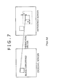
- FIG. 7 illustrates an original screen, reference screen and hierarchical vector.
- An input image and reference image are reduced at the same reduction ratio to the same resolution.
- a coarse motion search is performed using the reduced images.
- the coarse motion vector obtained here will be hereinafter referred to as a hierarchical vector.
- Japanese Patent Laid-Open No. 2007-274383 discloses that, during the transfer of the reference image data indicated by the motion vector from the image memory, it is determined whether any part of the reference image lies off the image frame, and that this determination is made in word units.
- Japanese Patent Laid-Open No. 2007-274383 does not disclose that the search area of the memory is accessed or searched in word units in the refinement using a hierarchical vector.
- a frame memory often includes an SDRAM (Synchronous Dynamic Random Access Memory).
- SDRAM Serial Dynamic Random Access Memory
- a frame memory is accessed in word units. Therefore, a refinement search does not necessarily fit properly in the word boundary.
- a frame memory is accessed in word units as described above.
- some data, although accessed, is not used for the refinement depending on the search area and hierarchical vector value.
- FIG. 1 illustrates the relationship between the search area and word mapping when reference data is mapped into the memory, with 8 ⁇ 1 pixels treated as one word and when the hierarchical vector value is ( ⁇ 2, 0) and refinement search area ( ⁇ 10, ⁇ 4) in the original image resolution plane.
- the filled area in FIG. 1 corresponds to the unused data. So long as the refinement search area is specified by fixed values as in this example, there is always unused data depending on the hierarchical vector value.
- An image information coding method performs a motion vector search based on hierarchical search in an image compression information device adapted to output image compression information.
- the image information coding method includes a step of compressing a plurality of frame images at a predetermined compression ratio to generate a plurality of reduced screens of lower hierarchical levels.
- the image information coding method further includes a step of searching for a first motion vector using the plurality of reduced screens.
- the image information coding method still further includes a step of switching between search areas in the memory in which the frame images are stored.
- the image information coding method still further includes a step of searching for a second motion vector using the first motion vector in the switched search area.
- the search areas should preferably be formed by providing an access unit.
- the access unit is a word
- access to a word is cancelled according to the proportion of a search target in that word.
- fine and coarse refinement areas having an arbitrary shape are provided for the accessed image data in the memory with the number of search computations stored.
- An image information coding apparatus performs a motion vector search based on hierarchical search in an image compression information device adapted to output image compression information.
- the image information coding apparatus includes a reduced screen generating device adapted to compress a plurality of frame images at a predetermined compression ratio to generate a plurality of reduced screens of lower hierarchical levels.
- the image information coding apparatus further includes a first motion prediction device adapted to search for a first motion vector using the plurality of reduced screens.
- the image information coding apparatus still further includes a second motion prediction device adapted to switch between search areas in the memory in which the frame images are stored to search for a second motion vector using the first motion vector in the switched search area.
- the present invention switches between refinement search areas according to the motion vector value in a reduced screen, thus providing faster refinement search for motion vector value and reduced number of memory accesses.
- the present invention also permits use of all data accessed during switching between refinement search areas, thus providing improved compression efficiency.
- FIG. 1 is a diagram illustrating the relationship between word boundaries and fixed refinement in a refinement search
- FIGS. 2A and 2B are diagrams for describing block matching used to search for hierarchical vectors
- FIGS. 3A to 3D are diagrams illustrating examples of search areas in the memory in a refinement search
- FIGS. 4A to 4D are diagrams illustrating search points in the memory in a refinement search
- FIGS. 5A and 5B are diagrams illustrating search points for other search shape in a refinement search
- FIG. 6 is a diagram illustrating the block configuration of an image information coding apparatus using hierarchical vector search.
- FIG. 7 is a diagram illustrating an example of relationship between the word boundaries and fixed refinement in a common refinement search.
- refinement search refers to a fine motion vector search using a hierarchical vector. It should be noted that the hierarchical vector is also called a coarse motion vector.
- a coarse motion vector is found in a reduced screen by block matching. Then, a refinement search is performed in the original image resolution plane using the coarse motion vector.
- Block matching used to find a coarse motion vector in a reduced screen will be described first, followed by the description of a refinement search.
- the identified image block on the reduced image plane is shifted one pixel at a time to find the absolute difference. This step is repeated to find a vector from the smallest sum of absolute differences.
- each block includes, for example, 4 ⁇ 4 pixels.
- the pixel numbers of the image blocks of the reference screen are r 0 , r 1 , r 2 and so on, whereas those of the original screen are c 0 , c 1 , c 2 and so on.
- the block numbers are written in a matrix notation in the equations as r(i, j) and c(i, j).
- the image block (n,m) and its surrounding area are, for example, searched.
- the reduced reference and original screens are produced by thinning out the numbers of image blocks thereof to 1/N (N: positive integer).
- Equation 2 represents (x,y) when the sum of absolute differences Sum(x,y) is smallest.
- Equation 2 the sums of absolute differences Sumx,y(0 ⁇ x ⁇ 3, 0 ⁇ y ⁇ 3), found by Equations 3 to 5, are substituted into Equation 2 to find a coarse motion vector MV x,y from the smallest of all the sums according to the definition.
- a search is performed for a coarse motion vector for each of the m ⁇ n blocks, i.e., (0, 0) through (n ⁇ 1,m ⁇ 1), in the frame.
- FIGS. 3A to 3D illustrate examples of two-dimensional mapping of the memory addresses.
- the memory generally includes a semiconductor storage device such as SDRAM (Static Dynamic Random Access Memory) and DRAM.
- FIGS. 3A to 3D illustrate examples of mapping of the reference screen data in a refinement search with each word containing 8 ⁇ 1 pixels.
- the word unit boundaries are shown by vertical lines, with each enclosed area representing one word unit containing 8 ⁇ 1 pixels.
- the area enclosed by thick dashed lines is a search area ‘e,’ and the area enclosed by solid lines an image block (area) ‘f’ of the search center.
- FIGS. 3A to 3D illustrate the relationship between the word boundaries and refinement search area when words are arranged in the memory in units of 8 ⁇ 1 pixels (also referred to as word units) and when the refinement search area is ( ⁇ 10, ⁇ 4) with respect to the image block ‘f.’
- FIGS. 3A to 3D show examples in which the mapped memory addresses are indicated by coordinates to facilitate the visual understanding thereof.
- the X coordinates range from ‘an ⁇ 24’ to ‘an+31,’ and the Y coordinates from ‘bn ⁇ 6’ to ‘bn+25.’
- the memory addresses are assigned coordinates (an ⁇ 24,bn ⁇ 6) through (an+31,bn+25), with vertical lines provided in the X coordinate direction to represent the 8 ⁇ 1 pixel boundaries for ease of viewing.
- the access unit in the X direction is 8 ⁇ 1 pixels.
- the present embodiment is not limited to this unit, and the access unit in the X direction may be the number of pixels stored in one word such as 4 ⁇ 2 pixels.
- the memory has four different patterns in the original image resolution plane depending on the hierarchical vector value (coarse motion vector) in the X direction according to the address position of the image area ‘f.’ The following describes the reason for this:
- the search area ‘e’ ranges from (an ⁇ 10,bn ⁇ 4) to (an+25,bn+19). Because the X coordinate start address of the image area ‘f’ is ‘an’ and fits in the 8 ⁇ 1 pixel unit. Therefore, there is no “remainder.”
- the search area ‘e’ ranges from (an ⁇ 10,bn ⁇ 4) to (an+21,bn+19).
- the image area ‘f,’ enclosed by solid lines ranges from (an ⁇ 4,bn) to (an+11,bn+15).
- the addresses of the image area ‘f’ are (an ⁇ 4,bn), (an ⁇ 4,bn+1), - - - , (an ⁇ 4,bn+1), (an ⁇ 3,bn+1), - - - , and (an+11,bn+15). If the X coordinate start address ‘an ⁇ 4’ is divided by the 8 ⁇ 1 pixel unit, the “remainder” is +4 when the X coordinate reference address is ‘an ⁇ 8.’ On the other hand, if the reference address is ‘an,’ the “remainder” is ⁇ 4. These results are shown under FIG. 3B .
- the addresses of the image area ‘f’ are (an ⁇ 2,bn), (an ⁇ 1,bn), - - - , (an ⁇ 1,bn+1), - - - , and (an+13,bn+15). If the X coordinate reference address is ‘an ⁇ 8,’ the “remainder” is +6. On the other hand, if the reference address is ‘an,’ the “remainder” is ⁇ 2. These results are shown under FIG. 3C .
- the “remainder” of the address with respect to the image block ‘f’ can be classified into four patterns. These four patterns assume that the reduction ratio for motion search is 1 ⁇ 2. In the above examples, therefore, the “remainder” takes on the values of 0, ⁇ 2, ⁇ 4 and ⁇ 6.
- the addresses of the image area ‘f’ range from (an,bn) to (an+15,bn+15). If the search area ‘e’ is larger than the image area ‘f’ by ⁇ 10 in the X direction and ⁇ 4 in the Y direction, the addresses of the search area ‘e’ range from (an ⁇ 10,bn ⁇ 4) to (an+25,bn+19).
- the X coordinate addresses are ‘an ⁇ 16,’ ‘an ⁇ 8,’ ‘an,’ - - - , ‘an+32’ and so on.
- search area ‘e’ is larger than the image area ‘f’ by ⁇ 10 in the X direction and ⁇ 4 in the Y direction, there may be a “remainder” relative to the address position of the image area ‘f’ depending on the start address of the search area ‘e’ in the X direction.
- the area ‘d’ ranging from (an ⁇ 16,bn ⁇ 4) to (an ⁇ 11,bn+19) and an area ‘h’ ranging from (an+26,bn ⁇ 4) to (an+31,bn+19) are accessed.
- the first embodiment of the present invention cancels access if the effective search area is small at the boundary between 8 ⁇ 1 pixel units (word units).
- the memory addresses to be searched are set, for example, to be (an ⁇ 8,bn ⁇ 4) to (an+23,bn+19).
- the search area ‘e’ is smaller than the common one. That is, an area ranging from (an ⁇ 16,bn ⁇ 4) to (an ⁇ 9,bn+19) and another area ranging from (an+24,bn ⁇ 4) to (an+31,bn+19) are not searched.
- the X coordinates of the memory map in the search area may be changed in units of 8 ⁇ 1 pixels although this is a tradeoff with the compression efficiency.
- the search area may range from (an ⁇ 8,bn ⁇ 4) to (an+31,bn+19) or (an ⁇ 16,bn ⁇ 4) to (an+23,bn+19).
- cancelling the data access to the addresses from ‘an+16’ to ‘an+9’ provides not only reduced power consumption required for memory access but also faster refinement.
- FIG. 3B illustrates a case in which the address positions of the image area ‘f’ are different.
- the memory access is performed in the same manner as in FIG. 3A .
- the search area of the past ‘e’ ranges from (an ⁇ 14,bn ⁇ 4) to (an+21,bn+19). As described above, however, if the memory is searched in units of 8 ⁇ 1 pixels, the memory search area ‘e’ may be changed to range from (an ⁇ 8,bn ⁇ 4) to (an+23,bn+19).
- the search area ‘e’ can be set to various ranges, such as between (an ⁇ 8,bn ⁇ 4) and (an+15,bn+19) and between (an ⁇ 16,bn ⁇ 4) and (an+15,bn+19).
- the search area of the past may be left unchanged because the fixed search area accounts for a large proportion per access. This range should be selected according to the processing time, the direction of the hierarchical motion vector and so on.
- the memory is searched in word units.
- the X coordinate end address of the search area ‘e’ is ‘an+23,’ which is an integer multiple of the 8 ⁇ 1 pixel unit.
- the start address of the search area ‘e’ does not fit in the word unit. Therefore, only the area whose X coordinate address is ‘an ⁇ 8’ or less is not searched.
- the X coordinate start address of the search area ‘e’ is ‘an ⁇ 16,’ which is an integer multiple of the 8 ⁇ 1 pixel unit.
- the end address of the search area ‘e’ does not fit in the 8 ⁇ 1 pixel unit. Therefore, the area whose X coordinate address is ‘an+16’ or more is not searched.
- searching the memory in units of 8 ⁇ 1 pixels during the refinement using a hierarchical vector provides reduced power consumption thanks to reduced number of memory accesses and permits motion search in a short period of time.
- the present embodiment cancels access to a word string according to the proportion of the search target pixels in the word.
- the first embodiment described above is an approach designed to cancel search to the word string concerned according to the proportion of the effective pixels in the word in the fixed refinement search area.
- the second embodiment of the present invention accesses the areas which will not be searched, but effectively uses the obtained data. In other words, the second embodiment searches all the areas including the filled ones in FIG. 3 .
- the number of search points is selected in the following manner according to the area to be searched so as to provide improved search efficiency.
- FIGS. 4A to 4D illustrate the search points when the search unit is a macroblock.
- the search center is located, for example, at the coordinates (an,bn) of the memory map.
- FIGS. 4A to 4D show that the search points are searched in a discrete manner. The filled points are not searched, thus reducing the number of points searched.
- the area containing the points to be searched in a discrete manner relative to the refinement center ranges from ⁇ 16 (an ⁇ 16) to ⁇ 7 (an ⁇ 7) in the X (coordinate) direction. More specifically, in the memory map shown in FIG. 4A , a search is performed in a discrete manner on the points (an ⁇ 16,bn ⁇ 4), (an ⁇ 14,bn ⁇ 4), (an ⁇ 12,bn ⁇ 4), - - - , (an ⁇ 16,bn+4), - - - , and (an ⁇ 8,bn+4).
- the area ranging from +7 (an+7) to +16 (an+16) in the X (coordinate) direction is searched.
- a search is performed in a discrete manner on the points (an+7,bn ⁇ 4), (an+9,bn ⁇ 4), - - - , (an+7,bn+4), - - - , and (an+15,bn+4).
- an area ranging from (an ⁇ 16,bn ⁇ 4) to (an ⁇ 13,bn+4) and another area ranging from (an+5,bn ⁇ 4) to (an+8,bn+4) are searched in a discrete manner.
- the area other than the above which ranges from (an ⁇ 12,bn ⁇ 4) to (an+4,bn+4) all the points are searched.
- FIGS. 4C and 4D a search is performed in the same manner as described above.
- the search method shown in FIG. 4 is merely an example. As long as the number of search points is stored, the search area, in principle, can take any shape.
- the search area ‘e’ may be rhombic in which the distance between the search center (an,bn) and each of the hierarchical vectors is the same. All the points within this rhombic area are searched. Outside this area, on the other hand, every other points are searched. In addition to this, every three points (or even every four or more points) outside the rhombic area may be searched in a discrete manner.
- the search area may be pentagonal. Outside the search area, a coarse search is performed at intervals of a predetermined number of pixels. Inside the search area, on the other hand, all the pixels are searched.
- the present invention performs a fine search inside the specified area according to the magnitude of the hierarchical vector (coarse motion vector) and a coarse search at intervals outside the specified area.
- the search area is not limited to the above shapes.
- the search area may take any shape so long as it can classify the entire area into two parts. Therefore, the area may be, for example, polygonal, circular or elliptical.
- the present invention switches between refinement search areas in an image compression information coding device adapted to output image compression information according to the value of the coarse motion search vector in a reduced screen, thus ensuring effective use of accessed data and providing improved compression efficiency.
- the image information coding apparatus 100 includes an A/D (analog/digital) converter 101 , screen rearrangement buffer 102 , adder 103 , orthogonal transform device 104 , quantization device 105 , reversible coding device 106 , storage buffer 107 , inverse quantization device 108 , inverse orthogonal transform device 109 , deblocking filter 110 , frame memory (full resolution) 111 , thinning-out device 112 , frame memory (1/N 2 resolution) 113 , motion prediction/compensation device (1/N 2 resolution) 114 , intra-prediction device 115 , motion prediction/compensation device (full resolution) 116 and rate control device 117 .
- A/D analog/digital
- a video signal S in fed to the same apparatus 100 is first converted to a digital signal by the A/D converter 101 .
- the frames of the resultant signal are rearranged by the screen rearrangement buffer 102 according to the GOP structure of the image compression information to be output.
- the differential information between the input image and the pixel values generated by the intra-prediction device 115 is fed to the orthogonal transform device 104 for orthogonal transform such as discrete cosine transform and Karhunen-Loeve transform.
- the conversion factor from the orthogonal transform device 104 is supplied to the quantization device 105 for quantization.
- the quantized conversion factor from the quantization device 105 is fed to the reversible coding device 106 where the conversion factor undergoes reversible coding such as variable-length coding and arithmetic coding, after which the conversion factor is stored in the storage buffer 107 and output as image compression information S out .
- the operation of the quantization device 105 is controlled by the rate control device 117 .
- the quantized conversion factor from the quantization device 105 is fed to the inverse quantization device 108 for inverse quantization.
- the conversion factor is inversely orthogonally transformed by the inverse orthogonal transform device 109 to be restored to the original decoded image information.
- the decoded image information which has undergone inverse orthogonal transform is supplied to the deblocking filter 110 for removal of blocking distortion, followed by the storage of the information in the frame memory 111 .
- the information about intra-prediction mode applied to the blocks and macroblocks in the intra-prediction device 115 is transmitted to the reversible coding device 106 for coding as part of the header information in the image compression information.
- the image information is fed to the motion prediction/compensation device 116 .
- the reference image information is extracted from the frame memory 111 for motion prediction to generate reference image information.
- the reference image information is transmitted to the adder 103 for addition to the image information from the screen rearrangement buffer 102 , thus converting the reference image information to a differential signal.
- the thinning-out device 112 receives the image information stored in the frame memory 111 .
- the same device 112 thins out the information to 1/N (N: positive integer) both in the horizontal and vertical directions and stores the generated pixel values in the frame memory 113 .
- the motion prediction/compensation device 114 searches for the optimal coarse motion vector information for the block concerned through block matching using the pixel values stored in the frame memory 113 and the image blocks such as 4 ⁇ 4, 8 ⁇ 8 and 16 ⁇ 16 blocks.
- thinning-out is conducted separately for the first and second fields.
- the coarse motion vector information searched using a reduced screen is fed to the motion prediction/compensation device 116 .
- the motion prediction/compensation device 116 performs refinement using the reference screen with the original image resolution. The same device 116 does so by changing the manner in which it accesses the memory according to the search center address in units of a predetermined number of words as appropriate. It should be noted that the manner in which the memory is accessed may be changed in units of a predetermined number of bits rather than words.
- the same device 116 divides the search area into at least two parts using the reference screen with the original image resolution, searching all the areas close to the search center and searching those far from the search center in a discrete manner.
- the same device 116 simultaneously outputs motion vector information to the reversible coding device 106 where this information undergoes reversible coding such as variable-length coding and arithmetic coding, thus forming image compression information.
- the image information coding apparatus 100 reduces the number of searches performed as a result of the hierarchical search during access to the searched data in the frame memory, thus contributing to reduced power consumption and reduced number of computations (faster computations) in motion prediction (full resolution).
- the image information coding apparatus 100 configured as described above treats all the accessed data areas as the target areas for motion search and changes the manner in which it performs a search according to the distance from the search center to the hierarchical vector, thus providing improved compression efficiency.
- the reduced screen generating device adapted to compress a plurality of frame images at a predetermined compression ratio to generate a plurality of reduced screens of lower hierarchical levels corresponds to the thinning-out device 112 .
- the first motion prediction device adapted to search for a first motion vector using the plurality of reduced screens corresponds to the motion prediction/compensation device 114 .
- the second motion prediction device adapted to switch between search areas in the memory in which the frame images are stored to search for a second motion vector using the first motion vector in the switched search area corresponds to the motion prediction/compensation device 116 .
Abstract
Description
[Equation 1]
Sum(x,y)=Σi=0,3Σj=0,3{abs(r i,j −c i,j)} (1)
[Equation 2]
MV x,y=minSum(x,y) (2)
[Equation 3]
Sum(0,0)=|r0−c0|+|r1−c1|+|r2−c2|+|r3−c3|+|r8−c4|+ - - - +|r27−c15| (3)
[Equation 4]
Sum(0,1)=|r1−c0|+|r2−c1|+|r3−c2|+|r4−c3|+|r9−c4|+ - - - - +|r28−c15| (4)
[Equation 5]
Sum(3,3)=|r27−c0|+|r28−c1|+|r29−c2|+|r30−c3|+|r35−c4|+ - - - +|r54−c15| (5)
Claims (15)
Applications Claiming Priority (2)
| Application Number | Priority Date | Filing Date | Title |
|---|---|---|---|
| JP2009106245A JP5141633B2 (en) | 2009-04-24 | 2009-04-24 | Image processing method and image information encoding apparatus using the same |
| JPP2009-106245 | 2009-04-24 |
Publications (2)
| Publication Number | Publication Date |
|---|---|
| US20100272181A1 US20100272181A1 (en) | 2010-10-28 |
| US8565312B2 true US8565312B2 (en) | 2013-10-22 |
Family
ID=42992117
Family Applications (1)
| Application Number | Title | Priority Date | Filing Date |
|---|---|---|---|
| US12/761,646 Active 2031-03-23 US8565312B2 (en) | 2009-04-24 | 2010-04-16 | Image processing method and image information coding apparatus using the same |
Country Status (3)
| Country | Link |
|---|---|
| US (1) | US8565312B2 (en) |
| JP (1) | JP5141633B2 (en) |
| CN (1) | CN101873490B (en) |
Cited By (1)
| Publication number | Priority date | Publication date | Assignee | Title |
|---|---|---|---|---|
| US20180262761A1 (en) * | 2017-03-08 | 2018-09-13 | Canon Kabushiki Kaisha | Image coding apparatus, image coding method, and storage medium |
Families Citing this family (7)
| Publication number | Priority date | Publication date | Assignee | Title |
|---|---|---|---|---|
| JP5141633B2 (en) * | 2009-04-24 | 2013-02-13 | ソニー株式会社 | Image processing method and image information encoding apparatus using the same |
| KR101910110B1 (en) | 2011-09-26 | 2018-12-31 | 삼성디스플레이 주식회사 | Display device and driving method thereof |
| KR101920885B1 (en) | 2011-09-29 | 2018-11-22 | 삼성디스플레이 주식회사 | Display device and driving method thereof |
| CN103916583B (en) * | 2013-01-08 | 2017-11-14 | 聚晶半导体股份有限公司 | Image denoising method and its method for producing motion-vector data structure |
| JP6323185B2 (en) * | 2014-06-04 | 2018-05-16 | 富士通株式会社 | Moving picture coding apparatus, moving picture coding method, and moving picture coding computer program |
| JP7005480B2 (en) * | 2018-12-27 | 2022-01-21 | Kddi株式会社 | Image decoder, image coding device, program and image processing system |
| CN111127310B (en) * | 2019-12-13 | 2023-06-06 | 北京奇艺世纪科技有限公司 | Image processing method and device, electronic equipment and storage medium |
Citations (56)
| Publication number | Priority date | Publication date | Assignee | Title |
|---|---|---|---|---|
| US5398143A (en) * | 1992-12-01 | 1995-03-14 | Samsung Electronics Co., Ltd. | Data placement on tape for a digital video tape recorder suitable for high speed picture playback |
| US5526131A (en) * | 1992-12-01 | 1996-06-11 | Samsung Electronics Co., Ltd | Data coding for a digital video tape recorder suitable for high speed picture playback |
| US5583580A (en) * | 1994-10-08 | 1996-12-10 | Daewoo Electronics Co., Ltd. | Method and apparatus for detecting motion vectors based on hierarchical motion estimation |
| US5623313A (en) * | 1995-09-22 | 1997-04-22 | Tektronix, Inc. | Fractional pixel motion estimation of video signals |
| US5684538A (en) * | 1994-08-18 | 1997-11-04 | Hitachi, Ltd. | System and method for performing video coding/decoding using motion compensation |
| US5703877A (en) * | 1995-11-22 | 1997-12-30 | General Instrument Corporation Of Delaware | Acquisition and error recovery of audio data carried in a packetized data stream |
| US5717470A (en) * | 1995-09-15 | 1998-02-10 | Daewoo Electronics, Co., Ltd. | Method and apparatus for detecting optimum motion vectors based on a hierarchical motion estimation approach |
| US5731851A (en) * | 1995-03-15 | 1998-03-24 | Daewoo Electronics, Co., Ltd. | Method for determining feature points based on hierarchical block searching technique |
| US5731850A (en) * | 1995-06-07 | 1998-03-24 | Maturi; Gregory V. | Hybrid hierarchial/full-search MPEG encoder motion estimation |
| US5742710A (en) * | 1994-02-23 | 1998-04-21 | Rca Thomson Licensing Corporation | Computationally-efficient method for estimating image motion |
| US5748247A (en) * | 1996-04-08 | 1998-05-05 | Tektronix, Inc. | Refinement of block motion vectors to achieve a dense motion field |
| US5754237A (en) * | 1995-03-20 | 1998-05-19 | Daewoo Electronics Co., Ltd. | Method for determining motion vectors using a hierarchical motion estimation |
| US5815602A (en) * | 1994-09-02 | 1998-09-29 | Texas Instruments Incorporated | DCT image compression and motion compensation using the hadamard transform |
| US5838392A (en) * | 1998-03-19 | 1998-11-17 | United Microelectronics Corp. | Adaptive block-matching motion estimator with a compression array for use in a video coding system |
| US6075875A (en) * | 1996-09-30 | 2000-06-13 | Microsoft Corporation | Segmentation of image features using hierarchical analysis of multi-valued image data and weighted averaging of segmentation results |
| JP2000175202A (en) | 1998-12-09 | 2000-06-23 | Victor Co Of Japan Ltd | Motion vector detector |
| US6108378A (en) * | 1993-12-30 | 2000-08-22 | Deutsche Thomson-Brandt Gmbh | Video encoder and decoder image motion estimation system with reduced computation |
| US20020009143A1 (en) * | 2000-06-27 | 2002-01-24 | Bamboo Mediacasting, Inc. | Bandwidth scaling of a compressed video stream |
| US6360027B1 (en) * | 1996-02-29 | 2002-03-19 | Acuson Corporation | Multiple ultrasound image registration system, method and transducer |
| US20020181745A1 (en) * | 2001-06-05 | 2002-12-05 | Hu Shane Ching-Feng | Multi-modal motion estimation for video sequences |
| US6594397B1 (en) * | 2000-03-03 | 2003-07-15 | Tektronix, Inc. | Adaptive multi-modal motion estimation for video compression |
| US20040212729A1 (en) * | 1997-03-17 | 2004-10-28 | Takao Yamaguchi | Method and apparatus for processing a data series including processing priority data |
| US20040252766A1 (en) * | 2003-06-11 | 2004-12-16 | Daeyang Foundation (Sejong University) | Motion vector search method and apparatus |
| US20040258154A1 (en) * | 2003-06-19 | 2004-12-23 | Microsoft Corporation | System and method for multi-stage predictive motion estimation |
| US6895048B2 (en) * | 1998-03-20 | 2005-05-17 | International Business Machines Corporation | Adaptive encoding of a sequence of still frames or partially still frames within motion video |
| US6928116B2 (en) * | 2003-05-20 | 2005-08-09 | Pantech Co., Ltd. | Motion estimation method using multilevel successive elimination algorithm |
| US20050232356A1 (en) * | 2004-04-20 | 2005-10-20 | Shinichiro Gomi | Image processing apparatus, method, and program |
| US7002587B2 (en) * | 2002-12-09 | 2006-02-21 | Sony Corporation | Semiconductor device, image data processing apparatus and method |
| US7020201B2 (en) * | 2002-11-20 | 2006-03-28 | National Chiao Tung University | Method and apparatus for motion estimation with all binary representation |
| US20060203912A1 (en) * | 2005-03-14 | 2006-09-14 | Tomoya Kodama | Motion vector detection method, motion vector detection apparatus, computer program for executing motion vector detection process on computer |
| JP2006295528A (en) | 2005-04-11 | 2006-10-26 | Pioneer Electronic Corp | Image signal processing method |
| US20060256864A1 (en) * | 2005-05-13 | 2006-11-16 | Mediatek Incorporation | Motion estimation methods and systems in video encoding for battery-powered appliances |
| US20070019721A1 (en) * | 2005-07-22 | 2007-01-25 | Canon Kabushiki Kaisha | Method and device for processing a sequence of digital images with spatial or quality scalability |
| US7203369B2 (en) * | 2002-08-13 | 2007-04-10 | Samsung Electronics Co., Ltd. | Method for estimating motion by referring to discrete cosine transform coefficients and apparatus therefor |
| US7260148B2 (en) * | 2001-09-10 | 2007-08-21 | Texas Instruments Incorporated | Method for motion vector estimation |
| JP2007274383A (en) | 2006-03-31 | 2007-10-18 | Oki Electric Ind Co Ltd | Data transfer circuit for image processing |
| US20080025395A1 (en) * | 2006-07-27 | 2008-01-31 | General Instrument Corporation | Method and Apparatus for Motion Estimation in a Video Encoder |
| US20080031335A1 (en) * | 2004-07-13 | 2008-02-07 | Akihiko Inoue | Motion Detection Device |
| US7362808B2 (en) * | 2002-12-09 | 2008-04-22 | Samsung Electronics Co., Ltd. | Device for and method of estimating motion in video encoder |
| US7420992B1 (en) * | 2005-03-17 | 2008-09-02 | Packeteer, Inc. | Adaptive network traffic compression mechanism including dynamic selection of compression algorithms |
| US20080298457A1 (en) * | 2004-07-28 | 2008-12-04 | Tomofumi Yamanashi | Relay Device and Signal Decoding Device |
| JP2009071642A (en) | 2007-09-14 | 2009-04-02 | Canon Inc | Moving image encoding device |
| US7602851B2 (en) * | 2003-07-18 | 2009-10-13 | Microsoft Corporation | Intelligent differential quantization of video coding |
| US20100014588A1 (en) * | 2008-07-16 | 2010-01-21 | Sony Corporation, A Japanese Corporation | Speculative start point selection for motion estimation iterative search |
| US7711044B1 (en) * | 2001-10-29 | 2010-05-04 | Trident Microsystems (Far East) Ltd. | Noise reduction systems and methods |
| US20100272181A1 (en) * | 2009-04-24 | 2010-10-28 | Toshiharu Tsuchiya | Image processing method and image information coding apparatus using the same |
| US20100284465A1 (en) * | 2006-09-18 | 2010-11-11 | Ulrich-Lorenz Benzler | Method for compressing data in a video sequence |
| US7852939B2 (en) * | 2004-10-18 | 2010-12-14 | Kabushiki Kaisha Toshiba | Motion vector detection method and device of the same |
| US7881376B2 (en) * | 2004-05-14 | 2011-02-01 | Panasonic Corporation | Motion compensation apparatus |
| US20110050930A1 (en) * | 2009-09-02 | 2011-03-03 | Sony Corporation | Fast iterative motion estimation method on gradually changing images |
| US20110158320A1 (en) * | 2008-09-04 | 2011-06-30 | Yunfei Zheng | Methods and apparatus for prediction refinement using implicit motion predictions |
| US8019000B2 (en) * | 2005-02-24 | 2011-09-13 | Sanyo Electric Co., Ltd. | Motion vector detecting device |
| US8046214B2 (en) * | 2007-06-22 | 2011-10-25 | Microsoft Corporation | Low complexity decoder for complex transform coding of multi-channel sound |
| US8144779B2 (en) * | 2006-06-19 | 2012-03-27 | Sony Corporation | Apparatus and method for detecting motion vector, program, and recording medium |
| US8155195B2 (en) * | 2006-04-07 | 2012-04-10 | Microsoft Corporation | Switching distortion metrics during motion estimation |
| US8175145B2 (en) * | 2007-06-14 | 2012-05-08 | France Telecom | Post-processing for reducing quantization noise of an encoder during decoding |
Family Cites Families (4)
| Publication number | Priority date | Publication date | Assignee | Title |
|---|---|---|---|---|
| US5682208A (en) * | 1994-10-31 | 1997-10-28 | Intel Corporation | Motion estimation with efficient block matching |
| JPH08265770A (en) * | 1995-03-20 | 1996-10-11 | Sony Corp | High efficiency encoding method, high efficiency encoder, recording and reproducing device and information transmission system |
| JP4165070B2 (en) * | 2002-01-11 | 2008-10-15 | ソニー株式会社 | Semiconductor memory device, motion vector detection device, and motion compensated prediction encoding device |
| US8462850B2 (en) * | 2004-07-02 | 2013-06-11 | Qualcomm Incorporated | Motion estimation in video compression systems |
-
2009
- 2009-04-24 JP JP2009106245A patent/JP5141633B2/en not_active Expired - Fee Related
-
2010
- 2010-04-16 US US12/761,646 patent/US8565312B2/en active Active
- 2010-04-19 CN CN2010101519243A patent/CN101873490B/en not_active Expired - Fee Related
Patent Citations (80)
| Publication number | Priority date | Publication date | Assignee | Title |
|---|---|---|---|---|
| US5526131A (en) * | 1992-12-01 | 1996-06-11 | Samsung Electronics Co., Ltd | Data coding for a digital video tape recorder suitable for high speed picture playback |
| US5574565A (en) * | 1992-12-01 | 1996-11-12 | Samsung Electronics Co., Ltd. | Data placement on tape for a digital video tape recorder suitable for high speed picture playback |
| US5398143A (en) * | 1992-12-01 | 1995-03-14 | Samsung Electronics Co., Ltd. | Data placement on tape for a digital video tape recorder suitable for high speed picture playback |
| US6108378A (en) * | 1993-12-30 | 2000-08-22 | Deutsche Thomson-Brandt Gmbh | Video encoder and decoder image motion estimation system with reduced computation |
| US5742710A (en) * | 1994-02-23 | 1998-04-21 | Rca Thomson Licensing Corporation | Computationally-efficient method for estimating image motion |
| US20080049840A1 (en) * | 1994-08-18 | 2008-02-28 | Yuichiro Nakaya | Video coding method and apparatus for calculating motion vectors of the vertices of a patch of an image and transmitting information of horizontal and vertical components of the motion vectors |
| US5963259A (en) * | 1994-08-18 | 1999-10-05 | Hitachi, Ltd. | Video coding/decoding system and video coder and video decoder used for the same system |
| US6516033B2 (en) * | 1994-08-18 | 2003-02-04 | Hitachi, Ltd. | Video coding method and apparatus for calculating motion vectors of the vertices of a portion of an image and outputting information of horizontal and vertical components of the motion vectors |
| US6542548B2 (en) * | 1994-08-18 | 2003-04-01 | Hitachi, Ltd. | Video coding method and apparatus for calculating motion vectors of the vertices of a patch of an image and transmitting information of horizontal and vertical components of the motion vectors |
| US7133454B2 (en) * | 1994-08-18 | 2006-11-07 | Hitachi, Ltd. | Video coding method and apparatus for calculating motion vectors of the vertices of a patch of an image and transmitting information of horizontal and vertical components of the motion vectors |
| US5684538A (en) * | 1994-08-18 | 1997-11-04 | Hitachi, Ltd. | System and method for performing video coding/decoding using motion compensation |
| US20080049839A1 (en) * | 1994-08-18 | 2008-02-28 | Yuichiro Nakaya | Video coding method and apparatus for calculating motion vectors of the vertices of a patch of an image and transmitting information of horizontal and vertical components of the motion vectors |
| US20080056370A1 (en) * | 1994-08-18 | 2008-03-06 | Yuichiro Nakaya | Video coding method and apparatus for calculating motion vectors of the vertices of a patch of an image and transmitting information of horizontal and vertical components of the motion vectors |
| US20030103569A1 (en) * | 1994-08-18 | 2003-06-05 | Yuichiro Nakaya | Video coding method and apparatus for calculating motion vectors of the vertices of a patch of an image and transmitting information of horizontal and vertical components of the motion vectors |
| US20080049838A1 (en) * | 1994-08-18 | 2008-02-28 | Yuichiro Nakaya | Video coding method and apparatus for calculating motion vectors of the vertices of a patch of an image and transmitting information of horizontal and vertical components of the motion vectors |
| US7680188B2 (en) * | 1994-08-18 | 2010-03-16 | Hitachi, Ltd. | Video coding method and apparatus for calculating motion vectors of the vertices of a patch of an image and transmitting information of horizontal and vertical components of the motion vectors |
| US20070002952A1 (en) * | 1994-08-18 | 2007-01-04 | Yuichiro Nakaya | Video coding method and apparatus for calculating motion vectors of the vertices of a patch of an image and transmitting information of horizontal and vertical components of the motion vectors |
| US20050232361A1 (en) * | 1994-08-18 | 2005-10-20 | Yuichiro Nakaya | Video coding method and apparatus for calculating motion vectors of the vertices of a patch of an image and transmitting information of horizontal and vertical components of the motion vectors |
| US6928117B2 (en) * | 1994-08-18 | 2005-08-09 | Hitachi, Ltd. | Video coding method and apparatus for calculating motion vectors of the vertices of a patch of an image and transmitting information of horizontal and vertical components of the motion vectors |
| US20020064229A1 (en) * | 1994-08-18 | 2002-05-30 | Yuichiro Nakaya | Video coding/decoding system and video coder and video decoder used for the same system |
| US6134271A (en) * | 1994-08-18 | 2000-10-17 | Hitachi, Ltd. | Video coding/decoding system and video coder and video decoder used for the same system |
| US6285713B1 (en) * | 1994-08-18 | 2001-09-04 | Hitachi, Ltd | Video coding/decoding system and video coder and video decoder used for the same system |
| US20010024473A1 (en) * | 1994-08-18 | 2001-09-27 | Yuichiro Nakaya | Video coding/decoding system and video coder and video decoder used for the same system |
| US7684487B2 (en) * | 1994-08-18 | 2010-03-23 | Hitachi, Ltd. | Video coding method and apparatus for calculating motion vectors of the vertices of a patch of an image and transmitting information of horizontal and vertical components of the motion vectors |
| US8135070B2 (en) * | 1994-08-18 | 2012-03-13 | Hitachi, Ltd. | Video coding method and apparatus for calculating motion vectors of the vertices of a patch of an image and transmitting information of horizontal and vertical components of the motion vectors |
| US5815602A (en) * | 1994-09-02 | 1998-09-29 | Texas Instruments Incorporated | DCT image compression and motion compensation using the hadamard transform |
| US5583580A (en) * | 1994-10-08 | 1996-12-10 | Daewoo Electronics Co., Ltd. | Method and apparatus for detecting motion vectors based on hierarchical motion estimation |
| US5731851A (en) * | 1995-03-15 | 1998-03-24 | Daewoo Electronics, Co., Ltd. | Method for determining feature points based on hierarchical block searching technique |
| US5754237A (en) * | 1995-03-20 | 1998-05-19 | Daewoo Electronics Co., Ltd. | Method for determining motion vectors using a hierarchical motion estimation |
| US5731850A (en) * | 1995-06-07 | 1998-03-24 | Maturi; Gregory V. | Hybrid hierarchial/full-search MPEG encoder motion estimation |
| US5926231A (en) * | 1995-08-10 | 1999-07-20 | Daewoo Electronics Co., Ltd. | Method and apparatus for detecting motion vectors based on hierarchical motion estimation |
| US5717470A (en) * | 1995-09-15 | 1998-02-10 | Daewoo Electronics, Co., Ltd. | Method and apparatus for detecting optimum motion vectors based on a hierarchical motion estimation approach |
| US5623313A (en) * | 1995-09-22 | 1997-04-22 | Tektronix, Inc. | Fractional pixel motion estimation of video signals |
| US5703877A (en) * | 1995-11-22 | 1997-12-30 | General Instrument Corporation Of Delaware | Acquisition and error recovery of audio data carried in a packetized data stream |
| US6360027B1 (en) * | 1996-02-29 | 2002-03-19 | Acuson Corporation | Multiple ultrasound image registration system, method and transducer |
| US5748247A (en) * | 1996-04-08 | 1998-05-05 | Tektronix, Inc. | Refinement of block motion vectors to achieve a dense motion field |
| US6075875A (en) * | 1996-09-30 | 2000-06-13 | Microsoft Corporation | Segmentation of image features using hierarchical analysis of multi-valued image data and weighted averaging of segmentation results |
| US20040212729A1 (en) * | 1997-03-17 | 2004-10-28 | Takao Yamaguchi | Method and apparatus for processing a data series including processing priority data |
| US5838392A (en) * | 1998-03-19 | 1998-11-17 | United Microelectronics Corp. | Adaptive block-matching motion estimator with a compression array for use in a video coding system |
| US6895048B2 (en) * | 1998-03-20 | 2005-05-17 | International Business Machines Corporation | Adaptive encoding of a sequence of still frames or partially still frames within motion video |
| JP2000175202A (en) | 1998-12-09 | 2000-06-23 | Victor Co Of Japan Ltd | Motion vector detector |
| US6594397B1 (en) * | 2000-03-03 | 2003-07-15 | Tektronix, Inc. | Adaptive multi-modal motion estimation for video compression |
| US6438168B2 (en) * | 2000-06-27 | 2002-08-20 | Bamboo Media Casting, Inc. | Bandwidth scaling of a compressed video stream |
| US20020009143A1 (en) * | 2000-06-27 | 2002-01-24 | Bamboo Mediacasting, Inc. | Bandwidth scaling of a compressed video stream |
| US6987866B2 (en) * | 2001-06-05 | 2006-01-17 | Micron Technology, Inc. | Multi-modal motion estimation for video sequences |
| US20020181745A1 (en) * | 2001-06-05 | 2002-12-05 | Hu Shane Ching-Feng | Multi-modal motion estimation for video sequences |
| US7260148B2 (en) * | 2001-09-10 | 2007-08-21 | Texas Instruments Incorporated | Method for motion vector estimation |
| US7711044B1 (en) * | 2001-10-29 | 2010-05-04 | Trident Microsystems (Far East) Ltd. | Noise reduction systems and methods |
| US7203369B2 (en) * | 2002-08-13 | 2007-04-10 | Samsung Electronics Co., Ltd. | Method for estimating motion by referring to discrete cosine transform coefficients and apparatus therefor |
| US7020201B2 (en) * | 2002-11-20 | 2006-03-28 | National Chiao Tung University | Method and apparatus for motion estimation with all binary representation |
| US7002587B2 (en) * | 2002-12-09 | 2006-02-21 | Sony Corporation | Semiconductor device, image data processing apparatus and method |
| US7362808B2 (en) * | 2002-12-09 | 2008-04-22 | Samsung Electronics Co., Ltd. | Device for and method of estimating motion in video encoder |
| US7590180B2 (en) * | 2002-12-09 | 2009-09-15 | Samsung Electronics Co., Ltd. | Device for and method of estimating motion in video encoder |
| US6928116B2 (en) * | 2003-05-20 | 2005-08-09 | Pantech Co., Ltd. | Motion estimation method using multilevel successive elimination algorithm |
| US20040252766A1 (en) * | 2003-06-11 | 2004-12-16 | Daeyang Foundation (Sejong University) | Motion vector search method and apparatus |
| US20040258154A1 (en) * | 2003-06-19 | 2004-12-23 | Microsoft Corporation | System and method for multi-stage predictive motion estimation |
| US7602851B2 (en) * | 2003-07-18 | 2009-10-13 | Microsoft Corporation | Intelligent differential quantization of video coding |
| US20050232356A1 (en) * | 2004-04-20 | 2005-10-20 | Shinichiro Gomi | Image processing apparatus, method, and program |
| US7881376B2 (en) * | 2004-05-14 | 2011-02-01 | Panasonic Corporation | Motion compensation apparatus |
| US20080031335A1 (en) * | 2004-07-13 | 2008-02-07 | Akihiko Inoue | Motion Detection Device |
| US20080298457A1 (en) * | 2004-07-28 | 2008-12-04 | Tomofumi Yamanashi | Relay Device and Signal Decoding Device |
| US7852939B2 (en) * | 2004-10-18 | 2010-12-14 | Kabushiki Kaisha Toshiba | Motion vector detection method and device of the same |
| US8019000B2 (en) * | 2005-02-24 | 2011-09-13 | Sanyo Electric Co., Ltd. | Motion vector detecting device |
| US20060203912A1 (en) * | 2005-03-14 | 2006-09-14 | Tomoya Kodama | Motion vector detection method, motion vector detection apparatus, computer program for executing motion vector detection process on computer |
| US7420992B1 (en) * | 2005-03-17 | 2008-09-02 | Packeteer, Inc. | Adaptive network traffic compression mechanism including dynamic selection of compression algorithms |
| JP2006295528A (en) | 2005-04-11 | 2006-10-26 | Pioneer Electronic Corp | Image signal processing method |
| US20060256864A1 (en) * | 2005-05-13 | 2006-11-16 | Mediatek Incorporation | Motion estimation methods and systems in video encoding for battery-powered appliances |
| US20070019721A1 (en) * | 2005-07-22 | 2007-01-25 | Canon Kabushiki Kaisha | Method and device for processing a sequence of digital images with spatial or quality scalability |
| JP2007274383A (en) | 2006-03-31 | 2007-10-18 | Oki Electric Ind Co Ltd | Data transfer circuit for image processing |
| US8155195B2 (en) * | 2006-04-07 | 2012-04-10 | Microsoft Corporation | Switching distortion metrics during motion estimation |
| US8144779B2 (en) * | 2006-06-19 | 2012-03-27 | Sony Corporation | Apparatus and method for detecting motion vector, program, and recording medium |
| US20080025395A1 (en) * | 2006-07-27 | 2008-01-31 | General Instrument Corporation | Method and Apparatus for Motion Estimation in a Video Encoder |
| US20100284465A1 (en) * | 2006-09-18 | 2010-11-11 | Ulrich-Lorenz Benzler | Method for compressing data in a video sequence |
| US8175145B2 (en) * | 2007-06-14 | 2012-05-08 | France Telecom | Post-processing for reducing quantization noise of an encoder during decoding |
| US8046214B2 (en) * | 2007-06-22 | 2011-10-25 | Microsoft Corporation | Low complexity decoder for complex transform coding of multi-channel sound |
| JP2009071642A (en) | 2007-09-14 | 2009-04-02 | Canon Inc | Moving image encoding device |
| US20100014588A1 (en) * | 2008-07-16 | 2010-01-21 | Sony Corporation, A Japanese Corporation | Speculative start point selection for motion estimation iterative search |
| US20110158320A1 (en) * | 2008-09-04 | 2011-06-30 | Yunfei Zheng | Methods and apparatus for prediction refinement using implicit motion predictions |
| US20100272181A1 (en) * | 2009-04-24 | 2010-10-28 | Toshiharu Tsuchiya | Image processing method and image information coding apparatus using the same |
| US20110050930A1 (en) * | 2009-09-02 | 2011-03-03 | Sony Corporation | Fast iterative motion estimation method on gradually changing images |
Non-Patent Citations (2)
| Title |
|---|
| Hierarchical Estimation of the motion vector field <http://homepages.inf.ed.ac.uk/rbf/CVonline/LOCAL-COPIES/AV0405/ZAMPOGLU/Hierarchicalestimation.html>. * |
| Hierarchical Estimation of the motion vector field <http://homepages.inf.ed.ac.uk/rbf/CVonline/LOCAL—COPIES/AV0405/ZAMPOGLU/Hierarchicalestimation.html>. * |
Cited By (2)
| Publication number | Priority date | Publication date | Assignee | Title |
|---|---|---|---|---|
| US20180262761A1 (en) * | 2017-03-08 | 2018-09-13 | Canon Kabushiki Kaisha | Image coding apparatus, image coding method, and storage medium |
| US10630993B2 (en) * | 2017-03-08 | 2020-04-21 | Canon Kabushiki Kaisha | Image coding apparatus, image coding method, and storage medium |
Also Published As
| Publication number | Publication date |
|---|---|
| JP5141633B2 (en) | 2013-02-13 |
| JP2010258767A (en) | 2010-11-11 |
| US20100272181A1 (en) | 2010-10-28 |
| CN101873490A (en) | 2010-10-27 |
| CN101873490B (en) | 2013-03-27 |
Similar Documents
| Publication | Publication Date | Title |
|---|---|---|
| US8565312B2 (en) | Image processing method and image information coding apparatus using the same | |
| US20230196503A1 (en) | Upscaling Lower Resolution Image Data for Processing | |
| JP2920208B2 (en) | Coding method of motion vector of moving image | |
| US8565308B2 (en) | Interframe prediction processor with address management mechanism for motion vector storage | |
| JP5992070B2 (en) | Image decoding apparatus, image decoding method, image encoding apparatus, image encoding method, and data structure of encoded data | |
| EP2184924A2 (en) | Caching method and apparatus for video motion compensation | |
| KR100714698B1 (en) | Enhanced motion estimation method, video encoding method and apparatus using the same | |
| US20150010080A1 (en) | Apparatus and method for encoding/decoding images for intra-prediction | |
| JP4405516B2 (en) | Rectangular motion search | |
| CN102369730A (en) | Compressed dynamic image encoding device, compressed dynamic image decoding device, compressed dynamic image encoding method and compressed dynamic image decoding method | |
| JP4590335B2 (en) | Image processing apparatus and image processing method | |
| TW201031213A (en) | Low-power and high-performance video coding method for performing motion estimation | |
| CN101394559B (en) | Dynamic image processing method, decoding method and apparatus thereof | |
| JP5053774B2 (en) | Video encoding device | |
| KR100708183B1 (en) | Image storing device for motion prediction, and method for storing data of the same | |
| Bao et al. | An advanced hierarchical motion estimation scheme with lossless frame recompression for ultra high definition video coding | |
| JP2017183844A (en) | Image compression device, image compression method, and image compression program | |
| JPH11136674A (en) | Image coding method and storage medium | |
| KR100672376B1 (en) | Motion compensation method | |
| JP2009260660A (en) | Coding device and coding method | |
| JP2005210503A (en) | Video signal coding device |
Legal Events
| Date | Code | Title | Description |
|---|---|---|---|
| AS | Assignment |
Owner name: SONY CORPORATION, JAPAN Free format text: ASSIGNMENT OF ASSIGNORS INTEREST;ASSIGNORS:TSUCHIYA, TOSHIHARU;WADA, TORU;REEL/FRAME:024245/0648 Effective date: 20100204 |
|
| STCF | Information on status: patent grant |
Free format text: PATENTED CASE |
|
| FEPP | Fee payment procedure |
Free format text: PAYOR NUMBER ASSIGNED (ORIGINAL EVENT CODE: ASPN); ENTITY STATUS OF PATENT OWNER: LARGE ENTITY |
|
| AS | Assignment |
Owner name: SONY SEMICONDUCTOR SOLUTIONS CORPORATION, JAPAN Free format text: ASSIGNMENT OF ASSIGNORS INTEREST;ASSIGNOR:SONY CORPORATION;REEL/FRAME:040419/0001 Effective date: 20161006 |
|
| FPAY | Fee payment |
Year of fee payment: 4 |
|
| MAFP | Maintenance fee payment |
Free format text: PAYMENT OF MAINTENANCE FEE, 8TH YEAR, LARGE ENTITY (ORIGINAL EVENT CODE: M1552); ENTITY STATUS OF PATENT OWNER: LARGE ENTITY Year of fee payment: 8 |