US8566922B2 - System for isolating a secured data communication network - Google Patents
System for isolating a secured data communication network Download PDFInfo
- Publication number
- US8566922B2 US8566922B2 US13/115,362 US201113115362A US8566922B2 US 8566922 B2 US8566922 B2 US 8566922B2 US 201113115362 A US201113115362 A US 201113115362A US 8566922 B2 US8566922 B2 US 8566922B2
- Authority
- US
- United States
- Prior art keywords
- data
- internal
- computer
- computer system
- external
- Prior art date
- Legal status (The legal status is an assumption and is not a legal conclusion. Google has not performed a legal analysis and makes no representation as to the accuracy of the status listed.)
- Expired - Fee Related, expires
Links
Images


Classifications
-
- G—PHYSICS
- G06—COMPUTING; CALCULATING OR COUNTING
- G06F—ELECTRIC DIGITAL DATA PROCESSING
- G06F21/00—Security arrangements for protecting computers, components thereof, programs or data against unauthorised activity
- G06F21/50—Monitoring users, programs or devices to maintain the integrity of platforms, e.g. of processors, firmware or operating systems
- G06F21/55—Detecting local intrusion or implementing counter-measures
- G06F21/554—Detecting local intrusion or implementing counter-measures involving event detection and direct action
-
- H—ELECTRICITY
- H04—ELECTRIC COMMUNICATION TECHNIQUE
- H04L—TRANSMISSION OF DIGITAL INFORMATION, e.g. TELEGRAPHIC COMMUNICATION
- H04L63/00—Network architectures or network communication protocols for network security
- H04L63/02—Network architectures or network communication protocols for network security for separating internal from external traffic, e.g. firewalls
- H04L63/0209—Architectural arrangements, e.g. perimeter networks or demilitarized zones
Definitions
- the invention relates generally to data communications networks. More specifically, the invention relates to a system for isolating a secured data communication network.
- the invention relates to a system for isolating a data communication network, comprising: a secured internal computer system; an internal computer that is in data communication with the internal computer system; an unsecured external computer system; an external computer that is in data communication with the external computer system; an RJ45 ethernet jack that connects the internal computer with the external computer so that the internal computer system may transmit data to the external computer; and where the transmit pins on the RJ45 ethernet jack for the external computer are not connected to the internal computer to prevent transmission of data from the external computer to the internal computer.
- the invention relates to a system for isolating a data communication network, comprising: an internal computer system; an internal computer that is in data communication with the internal computer system; an external computer system; an external computer that is in data communication with the external computer system; and an ethernet adapter that connects the internal computer with the external computer so that data communication is established between the internal computer system and the external system, where the ethernet adapter only allows transmission of data from the internal computer system and prohibits the receipt of data by the internal computer system.
- the invention relates to a system for isolating a data communication network, comprising: an internal computer system; an external computer system; and means for allowing one way communication from the internal computer to the external computer system with an ethernet adapter.
- FIG. 1 shows a diagram of data network connectivity for a power plant in accordance with one embodiment of the present invention.
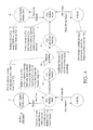
- FIG. 2 a shows a flow diagram for data connectivity and system security in accordance with one embodiment of the present invention.
- FIG. 2 b shows a schematic diagram of pin connections between computers for data connectivity and system security in accordance with one embodiment of the present invention.
- FIG. 3 shows overview diagram of a system for isolating a data communication network in accordance with one embodiment of the present invention.
- FIG. 4 shows a data flow diagram of a system for isolating a data communication network in accordance with one embodiment of the present invention.
- a system has been developed for isolating a secured data communication network.
- the system is placed between one computer system and another computer system to provide a true one-way communication interface. Data can flow in only one direction.
- FIG. 1 shows one example of data network connectivity for a nuclear power plant in accordance with the present invention.
- the system includes 4 levels of increasing security. On the exterior, is the internet which exists with essentially no security protection.
- Level 1 is a corporate wide area network (WAN) which represents connectivity between corporate assets. The assets have multi-directional communications (represented by the arrows) with the external internet and other levels. This allows communication and sharing of data between corporate offices, remote offices, power plants, etc.
- Level 2 is a site local area network (LAN) which houses local business applications such as finance, workflow applications, local intranet, e-mail services, etc. This level also allows multi-directional communications with the external internet and other levels.
- LAN site local area network
- Level 3 represents the first level with restricted communications.
- Level 3 is a data acquisition network that is primarily a plant system network and associated components that collect plant data.
- Level 3 is separated and isolated from Level 2 in that data may only flow to and not be received from Level 2 .
- Level 4 is the control and safety system network. It includes all plant control systems and it is separate and isolated from Level 3 with a one way communications path.
- the one way communications paths for Levels 3 and 4 are defensive in nature. The paths represent an interface boundary the allows one way data flow from Level 4 to Level 3 and from Level 3 to Level 2 . However, data is not allowed to pass back thus isolating Level 4 and Level 3 for security purposes.
- the present invention will be described using the example of a data network for a nuclear power plant consistent with FIG. 1 .
- the present invention can be applied with the same effectiveness for secure networks with other uses.
- the invention should not be limited to use with a network for a nuclear power plant but instead by the language of the claims.
- FIG. 2 a shows a flow diagram for data connectivity and system security in accordance with one embodiment of the present invention.
- the system includes a highly sensitive and secure Computer System 1 10 that is in data communication with Computer 1 12 (also listed as PC1).
- Computer 1 12 is communication with Computer 2 14 (also listed as PC2) through a one way data communication link 18 .
- Computer 2 14 is data communication with an external Computer System 2 16 .
- Both PC1 12 and PC2 14 run the Windows XP Operating System in one embodiment of the present invention.
- Computer System 1 10 is an internal computer or control system within a plant that provides data in a one-way fashion through the present invention.
- Computer System 2 16 is an external computer system within a plant that receives data in a one-way fashion from one way data communication link 18 that is located between two computer systems.
- the one way data communication link 18 is provided by using an “ethernet adapter”.
- “Ethernet” is a family of frame-based computer networking technologies for local area networks (LAN). It defines a number of wiring and signaling standards for the physical layer of the standard networking model as well as a common addressing format and a variety of medium access control (MAC) procedures at the lower part of the data link layer (DLL). It is standardized as IEEE Standard 802.3.
- An “ethernet adapter” is the hardware required to attach to an Ethernet network. It typically resides on an expansion board, but is sometimes built into the motherboard of a computer.
- PC1 12 performs poll-and-receive communications with Computer System 1 10 .
- PC1 12 then sends this data via a one-way Ethernet interface 18 to PC2 14 .
- the transmit wiring from PC2 14 to PC1 12 is not connected—this provides a physical isolation of PC2 14 to PC1 12 .
- Computer System 2 then performs poll-and-receive communications with PC2 14 .
- connection interface between PC1 12 and PC2 14 shown in FIG. 2 b A standard RJ45 Ethernet jack is used.
- the standard pin-outs for this jack are: Pins 1 and 2—Transmit; and Pins 3 and 6—Receive.
- a special adapter is installed in the present invention to achieve this connection.
- the ethernet port hardware detects transmitted signals and thereby generates a link light.
- the same transmit pair of wires are connected to the receive pair on PC2 14 .
- the transmit pair on PC2 14 is not connected.
- PC1 12 is capable of transmitting information to PC2 14 and PC2 14 cannot transmit information to PC1 12 . Therefore, any computer system to which PC1 12 is connected cannot be communicated with using any computer system connected to PC2 14 .
- UDP/IP is a user datagram protocol/internet protocol which is a network transport that uses a simple transmission model. This standard does not employ handshaking to ensure data is properly transmitted from one point to another.
- CRC is a cyclic redundancy check which is a software method that calculates a short, fixed-length binary sequence for each block of data and sends or stores them both together. When a block is received the device repeats the calculation. If the new CRC does not match the one sent, then the block is considered to contain a data error; otherwise the data is assumed to be error free.
- PC1 12 functions may include: performing poll-and-receive communications with an internal computer system via an ethernet port; retrieving packages of data retrieved the internal computer system; setting flags if communications with the internal computer system fails or if the system reports bad data is being sent; running intrusion detection to track Windows events and setting a flag if an event is detected; performing a CRC on obtained data; and transmitting data, CRC, and flags via a different ethernet network port.
- PC2 14 functions may include: receiving and unpacking data, CRC, and messages from PC1 12 ; performing a CRC calculation on the received data; setting a flag if no information is received from PC1 12 ; setting a flag if a different CRC from PC1 12 is calculated; setting a flag if communications with the internal computer system fails; running intrusion detection to track Windows events and setting a flag if an event is detected; and becoming a Modbus server to allow an external computer system to perform poll-and-receive communications to obtain data from the protected computer system.
- the “Modbus” protocol is presently employed on both PC1 12 and PC2 14 .
- “Modbus” is a high-level communication protocol for industrial networks that is widely used with TCP/IP over ethernet networks.
- PC1 12 performs Modbus client functions to receive information from an internal computer (e.g. control) system. Another interface could be written to bring in data to PC1 12 in other formats.
- the software modules for operating the system may be written in Microsoft C++ and compiled using version 8.
- the following examples are of modules that may be compiled into an executable file running on PC1.
- PC1 XMLFile This module reads an XML file that describes numerous attributes that are used by PC1 to perform its functions. The user can edit the XML file to change data that is obtained and transmitted, along with adjusting various limits. When the defined limits are exceeded, flags are generated. The module opens the file and determines the following: IP address of internal computer system with which it communicates; Modbus address ranges of points to be read from internal system; communications timeout limit (how long to wait on the internal communications system before declaring the connection lost); and quality limit (how many repetitive “bad” quality readings from the internal system are acceptable before PC1 sets the flag for bad quality of data).
- PC1 MBClient This module opens a communication link with the internal computer system. Modbus addresses defined in the XML file are requested from the internal computer system. The module then receives the data from the internal computer system, including any error messages. The data and error messages are placed into memory.
- PC1 DBMessage This module receives the information from MBClient and IntrusionDetection modules for delivery through DBSender to PC2.
- the message contains: data from internal computer system; quality code for no communications with the internal computer system; “bad” quality code from the internal computer system; Modbus error messages; and intrusion detection flag.
- PC1 IntrusionDetection This module receives an input from “Eventrecorder” software that may be installed on PC1. If any monitored Windows event is detected, the input will be received by this module, and this module sets a flag. The user is to determine the Windows events to be monitored.
- PC1 DBSender This module takes the DBMessage, adds necessary information such as the starting address, and builds Modbus packets to transmit to PC2. Before transmitting a packet to PC2, this module performs a CRC on the data.
- PC2 XMLFile This module reads the XML file that describes numerous attributes that are used by PC2 to perform its functions. (It should be noted that this is the same file that is on PC1.) The user can edit the XML file to change data that is obtained and transmitted, along with adjusting various limits. When the defined limits are exceeded, flags are generated. The module opens the file and determines the following: Modbus address ranges of points to be read from internal system; communications timeout limit (how long to wait on the PC1 communications before declaring the connection lost); and quality limit (how many repetitive “bad” CRC checks on data from PC1 are acceptable before PC2 sets the flag for bad quality of data).
- PC2 DBReceiver This module receives the data transmitted from PC1. It unpacks the data and prepares it for use on PC2's Modbus server. This module performs a CRC on the received data and compares it to the CRC calculated by PC1 for accuracy.
- PC2 QualityCode This module develops the quality code Modbus status register, which is user-defined in the XML file. Quality codes are single bits that indicate the following attributes (by bit in the status register; a logic “1” indicates the specified message is TRUE):
- PC2 IntrusionDetection This module receives an input from “Eventrecorder” software that is installed on PC2. If any monitored Windows event is detected, the input will be received by this module, and this module sets a flag. The user is to determine the Windows events to be monitored.
- the present invention tests to ensure the following are acceptable: applications automatically start on both PC1 and PC2 to transmit data from an “internal” computer to an “external” computer; data is appropriately transmitted from an “internal” computer to an “external” computer (a data transmission availability envelope is established from this testing where it is desirable for the data to contain 100 analog points and 1000 digital points transmitted at least 10 times per second); PC2 cannot transmit information to PC1; data transmission automatically recovers whenever events occur that interrupt service (i.e. network cable is disconnected/reconnected, PC1 is powered off/on, etc.); and appropriate quality codes are generated when:
Abstract
A system for isolating a data communication network has been developed. The system includes an internal computer system with an internal computer that is in data communication with the internal computer system, and an external computer system with an external computer that is in data communication with the external computer system. The internal and external computers are connected with an ethernet adapter that only allows transmission of data from the internal computer system and prohibits the receipt of data by the internal computer system.
Description
The invention relates generally to data communications networks. More specifically, the invention relates to a system for isolating a secured data communication network.
Security of computer networks is a growing concern, especially for data communication networks for sensitive sites such as nuclear plants, utility distribution systems, etc. The reliability of these networks is critically important and prevention of unauthorized access is fundamental to maintaining the operation and security of such network. Consequently, a system for isolating a secured data communication network from unauthorized access is highly desired.
In some aspects, the invention relates to a system for isolating a data communication network, comprising: a secured internal computer system; an internal computer that is in data communication with the internal computer system; an unsecured external computer system; an external computer that is in data communication with the external computer system; an RJ45 ethernet jack that connects the internal computer with the external computer so that the internal computer system may transmit data to the external computer; and where the transmit pins on the RJ45 ethernet jack for the external computer are not connected to the internal computer to prevent transmission of data from the external computer to the internal computer.
In other aspects, the invention relates to a system for isolating a data communication network, comprising: an internal computer system; an internal computer that is in data communication with the internal computer system; an external computer system; an external computer that is in data communication with the external computer system; and an ethernet adapter that connects the internal computer with the external computer so that data communication is established between the internal computer system and the external system, where the ethernet adapter only allows transmission of data from the internal computer system and prohibits the receipt of data by the internal computer system.
In other aspects, the invention relates to a system for isolating a data communication network, comprising: an internal computer system; an external computer system; and means for allowing one way communication from the internal computer to the external computer system with an ethernet adapter.
Other aspects and advantages of the invention will be apparent from the following description and the appended claims.
It should be noted that identical features in different drawings are shown with the same reference numeral.
A system has been developed for isolating a secured data communication network. The system is placed between one computer system and another computer system to provide a true one-way communication interface. Data can flow in only one direction.
For the purpose of explanation, the present invention will be described using the example of a data network for a nuclear power plant consistent with FIG. 1 . However, it should be clear that the present invention can be applied with the same effectiveness for secure networks with other uses. Thus, the invention should not be limited to use with a network for a nuclear power plant but instead by the language of the claims.
In this embodiment, Computer System 1 10 is an internal computer or control system within a plant that provides data in a one-way fashion through the present invention. Computer System 2 16 is an external computer system within a plant that receives data in a one-way fashion from one way data communication link 18 that is located between two computer systems. The one way data communication link 18 is provided by using an “ethernet adapter”. “Ethernet” is a family of frame-based computer networking technologies for local area networks (LAN). It defines a number of wiring and signaling standards for the physical layer of the standard networking model as well as a common addressing format and a variety of medium access control (MAC) procedures at the lower part of the data link layer (DLL). It is standardized as IEEE Standard 802.3. An “ethernet adapter” is the hardware required to attach to an Ethernet network. It typically resides on an expansion board, but is sometimes built into the motherboard of a computer.
During the operation of the system, PC1 12 performs poll-and-receive communications with Computer System 1 10. PC1 12 then sends this data via a one-way Ethernet interface 18 to PC2 14. The transmit wiring from PC2 14 to PC1 12 is not connected—this provides a physical isolation of PC2 14 to PC1 12. Computer System 2 then performs poll-and-receive communications with PC2 14.
Protection of the PC1 12 side of the present invention is achieved by the connection interface between PC1 12 and PC2 14 shown in FIG. 2 b. A standard RJ45 Ethernet jack is used. The standard pin-outs for this jack are: Pins 1 and 2—Transmit; and Pins 3 and 6—Receive. A special adapter is installed in the present invention to achieve this connection. By connecting the transmit pair of wires on PC1 12 to it's receive pair, the ethernet port hardware detects transmitted signals and thereby generates a link light. The same transmit pair of wires are connected to the receive pair on PC2 14. The transmit pair on PC2 14 is not connected. With this connection scheme, PC1 12 is capable of transmitting information to PC2 14 and PC2 14 cannot transmit information to PC1 12. Therefore, any computer system to which PC1 12 is connected cannot be communicated with using any computer system connected to PC2 14.
As shown in FIGS. 3 and 4 , information is transmitted from PC1 12 to PC2 14 using the UDP/IP communication standard. “UDP/IP” is a user datagram protocol/internet protocol which is a network transport that uses a simple transmission model. This standard does not employ handshaking to ensure data is properly transmitted from one point to another. To provide an assurance of data integrity, both PC1 12 and PC2 14 perform a CRC calculation on the data. A “CRC” is a cyclic redundancy check which is a software method that calculates a short, fixed-length binary sequence for each block of data and sends or stores them both together. When a block is received the device repeats the calculation. If the new CRC does not match the one sent, then the block is considered to contain a data error; otherwise the data is assumed to be error free.
The software modules for operating the system may be written in Microsoft C++ and compiled using version 8. The following examples are of modules that may be compiled into an executable file running on PC1.
PC1 XMLFile—This module reads an XML file that describes numerous attributes that are used by PC1 to perform its functions. The user can edit the XML file to change data that is obtained and transmitted, along with adjusting various limits. When the defined limits are exceeded, flags are generated. The module opens the file and determines the following: IP address of internal computer system with which it communicates; Modbus address ranges of points to be read from internal system; communications timeout limit (how long to wait on the internal communications system before declaring the connection lost); and quality limit (how many repetitive “bad” quality readings from the internal system are acceptable before PC1 sets the flag for bad quality of data).
PC1 MBClient—This module opens a communication link with the internal computer system. Modbus addresses defined in the XML file are requested from the internal computer system. The module then receives the data from the internal computer system, including any error messages. The data and error messages are placed into memory.
PC1 DBMessage—This module receives the information from MBClient and IntrusionDetection modules for delivery through DBSender to PC2. The message contains: data from internal computer system; quality code for no communications with the internal computer system; “bad” quality code from the internal computer system; Modbus error messages; and intrusion detection flag.
PC1 IntrusionDetection—This module receives an input from “Eventrecorder” software that may be installed on PC1. If any monitored Windows event is detected, the input will be received by this module, and this module sets a flag. The user is to determine the Windows events to be monitored.
PC1 DBSender—This module takes the DBMessage, adds necessary information such as the starting address, and builds Modbus packets to transmit to PC2. Before transmitting a packet to PC2, this module performs a CRC on the data.
The following modules may be compiled into executable file running on PC2:
PC2 XMLFile—This module reads the XML file that describes numerous attributes that are used by PC2 to perform its functions. (It should be noted that this is the same file that is on PC1.) The user can edit the XML file to change data that is obtained and transmitted, along with adjusting various limits. When the defined limits are exceeded, flags are generated. The module opens the file and determines the following: Modbus address ranges of points to be read from internal system; communications timeout limit (how long to wait on the PC1 communications before declaring the connection lost); and quality limit (how many repetitive “bad” CRC checks on data from PC1 are acceptable before PC2 sets the flag for bad quality of data).
PC2 DBReceiver—This module receives the data transmitted from PC1. It unpacks the data and prepares it for use on PC2's Modbus server. This module performs a CRC on the received data and compares it to the CRC calculated by PC1 for accuracy.
PC2 QualityCode—This module develops the quality code Modbus status register, which is user-defined in the XML file. Quality codes are single bits that indicate the following attributes (by bit in the status register; a logic “1” indicates the specified message is TRUE):
-
- 0×00=Good
- 0×01=No data received on PC1 from control system
- 0×02=Intrusion detected on PC1
- 0×04=Modbus Exception occurred from control system to PC1
- 0×08=No data received on PC2 from PC1
- 0×10=Bad CRC on message (from PC1 to PC2)
- 0×20=Intrusion detected on PC2
- 0×40=Heartbeat (toggles between 0 and 1 at user-defined interval).
PC2 IntrusionDetection—This module receives an input from “Eventrecorder” software that is installed on PC2. If any monitored Windows event is detected, the input will be received by this module, and this module sets a flag. The user is to determine the Windows events to be monitored.
Finally, the present invention tests to ensure the following are acceptable: applications automatically start on both PC1 and PC2 to transmit data from an “internal” computer to an “external” computer; data is appropriately transmitted from an “internal” computer to an “external” computer (a data transmission availability envelope is established from this testing where it is desirable for the data to contain 100 analog points and 1000 digital points transmitted at least 10 times per second); PC2 cannot transmit information to PC1; data transmission automatically recovers whenever events occur that interrupt service (i.e. network cable is disconnected/reconnected, PC1 is powered off/on, etc.); and appropriate quality codes are generated when:
-
- a. PC1 does not communicate with the “internal” computer
- b. PC1 receives bad data from the “internal” computer
- c. PC1 does not communicate with PC2
- d. PC2 receives bad data from PC1
- e. Intrusions are detected on either PC1 or PC2.
While the invention has been described with respect to a limited number of embodiments, those skilled in the art, having benefit of this disclosure, will appreciate that other embodiments can be devised which do not depart from the scope of the invention as disclosed here. Accordingly, the scope of the invention should be limited only by the attached claims.
Claims (6)
1. A system for isolating a data communication network, comprising:
a secured internal computer system;
an internal computer that is in data communication with the internal computer system;
an unsecured external computer system;
an external computer that is in data communication with the external computer system;
an RJ45 ethernet jack that connects the internal computer with the external computer so that the internal computer system may transmit data to the external computer using a UDP/IP communication standard where the communication data integrity from the internal computer to the external computer is check with a cyclic redundancy check (CRC) calculation;
and where the transmit pins on the RJ45 ethernet jack for the external computer are not connected to the internal computer to prevent transmission of data from the external computer to the internal computer.
2. A system for isolating a data communication network, comprising:
an internal computer system;
an internal computer that is in data communication with the internal computer system;
an external computer system;
an external computer that is in data communication with the external computer system;
and an ethernet adapter that connects the internal computer with the external computer so that data communication is established between the internal computer system and the external system using a UDP/IP communication standard, where the ethernet adapter only allows transmission of data from the internal computer system and prohibits the receipt of data by the internal computer system and where the communication data integrity from the internal computer to the external computer is check with a cyclic redundancy check (CRC) calculation.
3. The system of claim 2 , where the ethernet adapter comprises an RJ45 ethernet jack that connects the internal computer and the external computer.
4. The system of claim 2 , where the transmit pins of the ethernet adapter for the external computer are not connected.
5. The system of claim 2 , where the internal computer communicates to the external computer using a Modbus communication protocol.
6. A system for isolating a data communication network, comprising:
an internal computer that is in data communication with an internal computer system;
an external computer that is in data communication with an external computer system;
and means for allowing one way communication from the internal computer to the external computer system using a UDP/IP communication standard with an ethernet adapter that connects the internal computer with the external computer so that data communication is established between the internal computer system and the external system and where the ethernet adapter only allows transmission of data from the internal computer system and prohibits the receipt of data by the internal computer system and where the communication data integrity from the internal computer to the external computer is check with a cyclic redundancy check (CRC) calculation.
Priority Applications (1)
| Application Number | Priority Date | Filing Date | Title |
|---|---|---|---|
| US13/115,362 US8566922B2 (en) | 2011-05-25 | 2011-05-25 | System for isolating a secured data communication network |
Applications Claiming Priority (1)
| Application Number | Priority Date | Filing Date | Title |
|---|---|---|---|
| US13/115,362 US8566922B2 (en) | 2011-05-25 | 2011-05-25 | System for isolating a secured data communication network |
Publications (2)
| Publication Number | Publication Date |
|---|---|
| US20120304279A1 US20120304279A1 (en) | 2012-11-29 |
| US8566922B2 true US8566922B2 (en) | 2013-10-22 |
Family
ID=47220208
Family Applications (1)
| Application Number | Title | Priority Date | Filing Date |
|---|---|---|---|
| US13/115,362 Expired - Fee Related US8566922B2 (en) | 2011-05-25 | 2011-05-25 | System for isolating a secured data communication network |
Country Status (1)
| Country | Link |
|---|---|
| US (1) | US8566922B2 (en) |
Cited By (1)
| Publication number | Priority date | Publication date | Assignee | Title |
|---|---|---|---|---|
| US20170054687A1 (en) * | 2015-08-20 | 2017-02-23 | Mitsubishi Hitachi Power Systems, Ltd. | Security system and communication control method |
Families Citing this family (5)
| Publication number | Priority date | Publication date | Assignee | Title |
|---|---|---|---|---|
| US10050933B2 (en) * | 2015-06-25 | 2018-08-14 | Michael Froelich | Structural data ferry system |
| US10469447B2 (en) * | 2015-03-16 | 2019-11-05 | Schweitzer Engineering Laboratories, Inc. | Network access gateway |
| CN109450933B (en) * | 2018-12-18 | 2021-07-20 | 岭澳核电有限公司 | Network system for nuclear power plant emergency network |
| US10868681B2 (en) | 2018-12-31 | 2020-12-15 | Schweitzer Engineering Laboratories, Inc. | Network link breaker |
| CN110278184A (en) * | 2019-03-29 | 2019-09-24 | 苏州玖品信息科技有限公司 | A kind of isolation of network security and data exchange oil field Network of Power application system |
Citations (20)
| Publication number | Priority date | Publication date | Assignee | Title |
|---|---|---|---|---|
| US6119228A (en) * | 1997-08-22 | 2000-09-12 | Compaq Computer Corporation | Method for securely communicating remote control commands in a computer network |
| US6317831B1 (en) * | 1998-09-21 | 2001-11-13 | Openwave Systems Inc. | Method and apparatus for establishing a secure connection over a one-way data path |
| US6345307B1 (en) | 1999-04-30 | 2002-02-05 | General Instrument Corporation | Method and apparatus for compressing hypertext transfer protocol (HTTP) messages |
| US6430690B1 (en) * | 1998-01-30 | 2002-08-06 | Certicom Corp. | Secure one-way authentication communication system |
| WO2003055146A1 (en) | 2001-11-15 | 2003-07-03 | Bmc Software, Inc. | System and method for secure communications with a remote computer program |
| US20040024882A1 (en) | 2002-07-30 | 2004-02-05 | Paul Austin | Enabling authorised-server initiated internet communication in the presence of network address translation (NAT) and firewalls |
| US20040158635A1 (en) | 2003-01-23 | 2004-08-12 | Digi International Inc.. | Secure terminal transmission system and method |
| US20050033990A1 (en) | 2003-05-19 | 2005-02-10 | Harvey Elaine M. | Method and system for providing secure one-way transfer of data |
| US20050165939A1 (en) | 2002-05-30 | 2005-07-28 | Metso Automation Oy | System, communication network and method for transmitting information |
| US20060072531A1 (en) * | 2004-10-04 | 2006-04-06 | Ewing Carrel W | Communication network |
| US20060080536A1 (en) * | 1999-07-02 | 2006-04-13 | Time Certain, Llc. | System and method for distributing trusted time |
| US20060271617A1 (en) | 2005-05-05 | 2006-11-30 | Hughes George L Jr | Network data distribution system and method |
| US7260833B1 (en) * | 2003-07-18 | 2007-08-21 | The United States Of America As Represented By The Secretary Of The Navy | One-way network transmission interface unit |
| US20070203970A1 (en) | 2006-02-13 | 2007-08-30 | Qualcomm Incorporated | Mechanism and method for controlling network access to a service provider |
| US20080259929A1 (en) * | 2007-04-18 | 2008-10-23 | Ronald Mraz | Secure one-way data transfer system using network interface circuitry |
| US20080301799A1 (en) | 2007-05-31 | 2008-12-04 | The Boeing Company | Method and apparatus for reliable, high speed data transfers in a high assurance multiple level secure environment |
| US20100013625A1 (en) * | 2006-07-07 | 2010-01-21 | Sure Technologies Pty Ltd | Redundant Data Path System |
| US20100070638A1 (en) * | 2006-07-07 | 2010-03-18 | Department Of Space, Isro | System and a method for secured data communication in computer networks by phantom connectivity |
| US20110153969A1 (en) * | 2009-12-18 | 2011-06-23 | William Petrick | Device and method to control communications between and access to computer networks, systems or devices |
| US20120291096A1 (en) * | 2011-05-12 | 2012-11-15 | Nokia Corporation | Method and apparatus for secure signing and utilization of distributed computations |
-
2011
- 2011-05-25 US US13/115,362 patent/US8566922B2/en not_active Expired - Fee Related
Patent Citations (22)
| Publication number | Priority date | Publication date | Assignee | Title |
|---|---|---|---|---|
| US6119228A (en) * | 1997-08-22 | 2000-09-12 | Compaq Computer Corporation | Method for securely communicating remote control commands in a computer network |
| US6430690B1 (en) * | 1998-01-30 | 2002-08-06 | Certicom Corp. | Secure one-way authentication communication system |
| US6317831B1 (en) * | 1998-09-21 | 2001-11-13 | Openwave Systems Inc. | Method and apparatus for establishing a secure connection over a one-way data path |
| US6345307B1 (en) | 1999-04-30 | 2002-02-05 | General Instrument Corporation | Method and apparatus for compressing hypertext transfer protocol (HTTP) messages |
| US20060080536A1 (en) * | 1999-07-02 | 2006-04-13 | Time Certain, Llc. | System and method for distributing trusted time |
| WO2003055146A1 (en) | 2001-11-15 | 2003-07-03 | Bmc Software, Inc. | System and method for secure communications with a remote computer program |
| US20050165939A1 (en) | 2002-05-30 | 2005-07-28 | Metso Automation Oy | System, communication network and method for transmitting information |
| US20040024882A1 (en) | 2002-07-30 | 2004-02-05 | Paul Austin | Enabling authorised-server initiated internet communication in the presence of network address translation (NAT) and firewalls |
| US20040158635A1 (en) | 2003-01-23 | 2004-08-12 | Digi International Inc.. | Secure terminal transmission system and method |
| US20050033990A1 (en) | 2003-05-19 | 2005-02-10 | Harvey Elaine M. | Method and system for providing secure one-way transfer of data |
| US7260833B1 (en) * | 2003-07-18 | 2007-08-21 | The United States Of America As Represented By The Secretary Of The Navy | One-way network transmission interface unit |
| US20060072531A1 (en) * | 2004-10-04 | 2006-04-06 | Ewing Carrel W | Communication network |
| US20060271617A1 (en) | 2005-05-05 | 2006-11-30 | Hughes George L Jr | Network data distribution system and method |
| US20070203970A1 (en) | 2006-02-13 | 2007-08-30 | Qualcomm Incorporated | Mechanism and method for controlling network access to a service provider |
| US8046821B2 (en) * | 2006-02-13 | 2011-10-25 | Qualcomm Incorporated | Mechanism and method for controlling network access to a service provider |
| US20100070638A1 (en) * | 2006-07-07 | 2010-03-18 | Department Of Space, Isro | System and a method for secured data communication in computer networks by phantom connectivity |
| US20100013625A1 (en) * | 2006-07-07 | 2010-01-21 | Sure Technologies Pty Ltd | Redundant Data Path System |
| US20080259929A1 (en) * | 2007-04-18 | 2008-10-23 | Ronald Mraz | Secure one-way data transfer system using network interface circuitry |
| US8068415B2 (en) * | 2007-04-18 | 2011-11-29 | Owl Computing Technologies, Inc. | Secure one-way data transfer using communication interface circuitry |
| US20080301799A1 (en) | 2007-05-31 | 2008-12-04 | The Boeing Company | Method and apparatus for reliable, high speed data transfers in a high assurance multiple level secure environment |
| US20110153969A1 (en) * | 2009-12-18 | 2011-06-23 | William Petrick | Device and method to control communications between and access to computer networks, systems or devices |
| US20120291096A1 (en) * | 2011-05-12 | 2012-11-15 | Nokia Corporation | Method and apparatus for secure signing and utilization of distributed computations |
Non-Patent Citations (1)
| Title |
|---|
| R. Kisner, Safety and Nonsafety communications . . Power Plants, Aug. 2007, pp. 1-68. * |
Cited By (2)
| Publication number | Priority date | Publication date | Assignee | Title |
|---|---|---|---|---|
| US20170054687A1 (en) * | 2015-08-20 | 2017-02-23 | Mitsubishi Hitachi Power Systems, Ltd. | Security system and communication control method |
| US10021072B2 (en) * | 2015-08-20 | 2018-07-10 | Mitsubishi Hitachi Power Systems, Ltd. | Security system and communication control method |
Also Published As
| Publication number | Publication date |
|---|---|
| US20120304279A1 (en) | 2012-11-29 |
Similar Documents
| Publication | Publication Date | Title |
|---|---|---|
| US8566922B2 (en) | System for isolating a secured data communication network | |
| US8576727B2 (en) | System and method for unique identifier exchange during auto-negotiation | |
| CN110324222B (en) | Vehicle CAN bus data interaction system and interaction method thereof | |
| US10966004B2 (en) | Hardware-enforced one-way information flow control device | |
| CN105868149A (en) | A serial port information transmission method and device | |
| CN112615858B (en) | Internet of things equipment monitoring method, device and system | |
| JP2002533792A (en) | Method and system for protecting the operation of a trusted internal network | |
| CN107124393B (en) | Remote host management over a network | |
| Ogletree | Upgrading and repairing networks | |
| EP4106267A1 (en) | Communication system and communication method for reporting compromised state in one-way transmission | |
| CN107426166A (en) | A kind of acquisition methods of information, device and electronic equipment | |
| CN108768841A (en) | AFDX security gateway systems and its transmission method | |
| US8661523B2 (en) | Mass storage lockout for USB devices on extended USB system | |
| CN203206281U (en) | Source code protection machine and source code protection system | |
| CN113872826B (en) | Network card port stability testing method, system, terminal and storage medium | |
| CN101316202B (en) | On-line diagnosis method and system of embedded software, embedded software device | |
| KR101389646B1 (en) | Communication device and communication method | |
| CN219554983U (en) | Network safety device | |
| KR20090040655A (en) | System and method for enterprise signature management and distribution for network attacks | |
| Cagalaban et al. | Scada network insecurity: Securing critical infrastructures through scada security exploitation | |
| CN103731314B (en) | A kind of detection method, system and the equipment of communication service abnormal behavior | |
| Humayed | Securing CAN-based cyber-physical systems | |
| US20220021545A1 (en) | Novel method of securing legacy analog sensor circuits used in physical security, premise access control and industrial scada applications | |
| CN116232746A (en) | Network safety device | |
| Nelson | International Standard Payload Rack to International Space Station, Software Interface Control Document Part 1: International Space Station Program Revision M |
Legal Events
| Date | Code | Title | Description |
|---|---|---|---|
| STCF | Information on status: patent grant |
Free format text: PATENTED CASE |
|
| FPAY | Fee payment |
Year of fee payment: 4 |
|
| FEPP | Fee payment procedure |
Free format text: MAINTENANCE FEE REMINDER MAILED (ORIGINAL EVENT CODE: REM.); ENTITY STATUS OF PATENT OWNER: SMALL ENTITY |
|
| LAPS | Lapse for failure to pay maintenance fees |
Free format text: PATENT EXPIRED FOR FAILURE TO PAY MAINTENANCE FEES (ORIGINAL EVENT CODE: EXP.); ENTITY STATUS OF PATENT OWNER: SMALL ENTITY |
|
| STCH | Information on status: patent discontinuation |
Free format text: PATENT EXPIRED DUE TO NONPAYMENT OF MAINTENANCE FEES UNDER 37 CFR 1.362 |
|
| FP | Lapsed due to failure to pay maintenance fee |
Effective date: 20211022 |