US8625106B2 - Method for optically scanning and measuring an object - Google Patents
Method for optically scanning and measuring an object Download PDFInfo
- Publication number
- US8625106B2 US8625106B2 US13/384,795 US201013384795A US8625106B2 US 8625106 B2 US8625106 B2 US 8625106B2 US 201013384795 A US201013384795 A US 201013384795A US 8625106 B2 US8625106 B2 US 8625106B2
- Authority
- US
- United States
- Prior art keywords
- samples
- measuring
- phase shift
- light beam
- laser scanner
- Prior art date
- Legal status (The legal status is an assumption and is not a legal conclusion. Google has not performed a legal analysis and makes no representation as to the accuracy of the status listed.)
- Active
Links
Images


Classifications
-
- G—PHYSICS
- G01—MEASURING; TESTING
- G01S—RADIO DIRECTION-FINDING; RADIO NAVIGATION; DETERMINING DISTANCE OR VELOCITY BY USE OF RADIO WAVES; LOCATING OR PRESENCE-DETECTING BY USE OF THE REFLECTION OR RERADIATION OF RADIO WAVES; ANALOGOUS ARRANGEMENTS USING OTHER WAVES
- G01S17/00—Systems using the reflection or reradiation of electromagnetic waves other than radio waves, e.g. lidar systems
- G01S17/02—Systems using the reflection of electromagnetic waves other than radio waves
- G01S17/06—Systems determining position data of a target
- G01S17/08—Systems determining position data of a target for measuring distance only
- G01S17/32—Systems determining position data of a target for measuring distance only using transmission of continuous waves, whether amplitude-, frequency-, or phase-modulated, or unmodulated
- G01S17/36—Systems determining position data of a target for measuring distance only using transmission of continuous waves, whether amplitude-, frequency-, or phase-modulated, or unmodulated with phase comparison between the received signal and the contemporaneously transmitted signal
-
- G—PHYSICS
- G01—MEASURING; TESTING
- G01S—RADIO DIRECTION-FINDING; RADIO NAVIGATION; DETERMINING DISTANCE OR VELOCITY BY USE OF RADIO WAVES; LOCATING OR PRESENCE-DETECTING BY USE OF THE REFLECTION OR RERADIATION OF RADIO WAVES; ANALOGOUS ARRANGEMENTS USING OTHER WAVES
- G01S17/00—Systems using the reflection or reradiation of electromagnetic waves other than radio waves, e.g. lidar systems
- G01S17/02—Systems using the reflection of electromagnetic waves other than radio waves
- G01S17/06—Systems determining position data of a target
- G01S17/42—Simultaneous measurement of distance and other co-ordinates
-
- G—PHYSICS
- G01—MEASURING; TESTING
- G01S—RADIO DIRECTION-FINDING; RADIO NAVIGATION; DETERMINING DISTANCE OR VELOCITY BY USE OF RADIO WAVES; LOCATING OR PRESENCE-DETECTING BY USE OF THE REFLECTION OR RERADIATION OF RADIO WAVES; ANALOGOUS ARRANGEMENTS USING OTHER WAVES
- G01S17/00—Systems using the reflection or reradiation of electromagnetic waves other than radio waves, e.g. lidar systems
- G01S17/88—Lidar systems specially adapted for specific applications
- G01S17/89—Lidar systems specially adapted for specific applications for mapping or imaging
-
- G—PHYSICS
- G01—MEASURING; TESTING
- G01S—RADIO DIRECTION-FINDING; RADIO NAVIGATION; DETERMINING DISTANCE OR VELOCITY BY USE OF RADIO WAVES; LOCATING OR PRESENCE-DETECTING BY USE OF THE REFLECTION OR RERADIATION OF RADIO WAVES; ANALOGOUS ARRANGEMENTS USING OTHER WAVES
- G01S7/00—Details of systems according to groups G01S13/00, G01S15/00, G01S17/00
- G01S7/48—Details of systems according to groups G01S13/00, G01S15/00, G01S17/00 of systems according to group G01S17/00
- G01S7/497—Means for monitoring or calibrating
Definitions
- the invention relates to a method for optically scanning and measuring an object.
- the surroundings of the laser scanner can be optically scanned and measured.
- One known method for this called “zero cross”, determines the zero crossings of modulation of the emission light beam and of the reception light beam. The temporal difference corresponds to the distance. Only a small number of locations are thus evaluated, namely the zero crossings.
- Embodiments of the present invention are based on the object of improving a method of the type mentioned hereinabove.
- the method according to embodiments of the present invention makes it possible firstly to carry out the scanning without correction and then to correct the samples by the correction of the phase shift.
- the phase shift which can be regarded as a distortion of the time or frequency domain, fluctuates over the phase angle corresponding to the distance.
- a virtual speed can be determined for the correction of the phase shift, the virtual speed supplying the approximated phase shift.
- An iterative determination of the virtual speed may be carried out. Instead of individual locations, the time signal can be utilized in its entirety.
- the phase shift can be substantially corrected in practice. The correction is effected on line before the samples are combined, with data reduction, to form the measuring points.
- FIG. 1 is a schematic illustration of a laser scanner with an object located in the surroundings of the laser scanner;
- FIG. 2 is a schematic illustration of the time signal
- FIG. 3 is a schematic illustration of the spectrum with frequency shift (cross-hatched).
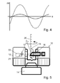
- FIG. 4 shows the phase shift dependent on the phase angle before the correction (dashed line) and afterwards (solid line);
- FIG. 5 is a side view, partially cut-away, of the laser scanner of FIG. 1 .
- a laser scanner 10 is provided as a device for optically scanning and measuring the surroundings of the laser scanner 10 .
- the laser scanner 10 has a measuring head 12 and a base 14 .
- the measuring head 12 is mounted on the base 14 as a unit that can be rotated about a vertical axis.
- the measuring head 12 has a mirror 16 that can be rotated about a horizontal axis. The point of intersection between the two axes of rotation is designated as the center C 10 of the laser scanner 10 .
- the measuring head 12 furthermore has a light emitter 17 for emitting an emission light beam 18 .
- the emission light beam 18 may be a laser beam in the visible range of wavelength of approximately 300 to 1000 nm, for example 790 nm, but other electromagnetic waves having, for example, a greater wavelength can also be used, in principle.
- the emission light beam 18 is amplitude-modulated with, for example, a sinusoidal or rectangular, modulation signal.
- the emission light beam 18 is passed from the light emitter 17 onto the mirror 16 , where it is deflected and emitted into the surroundings.
- a reception light beam 20 that is reflected or otherwise scattered in some way from an object O in the surroundings is captured again by the mirror 16 , deflected and passed onto a light receiver 21 .
- the direction of the emission light beam 18 and of the reception light beam 20 results from the angular positions of the mirror 16 and of the measuring head 12 , which depend on the positions of their respective rotary drives, which are in turn detected by respective encoders.
- a control and evaluation device 22 has a data link connection to the light emitter 17 and the light receiver 21 in the measuring head 12 , parts thereof also being arranged outside the measuring head 12 , for example as a computer connected to the base 14 .
- the control and evaluation device 22 is designed to determine, for a multiplicity of measuring points X, the distance d of the laser scanner 10 from the (illuminated point on the) object O from the propagation time of the emission light beam 18 and of the reception light beam 20 . For this purpose, the phase shift between the two light beams 18 , 20 is determined and evaluated.
- the center C 10 of the laser scanner 10 defines for such a scan the stationary reference system of the laser scanner 10 , in which the base 14 is stationary. Further details of the laser scanner 10 , in particular of the construction of the measuring head 12 , are described for example in U.S. Pat. No. 7,430,068 and DE 20 2006 005 643, the contents of which are incorporated by reference.
- the phase angle ⁇ is determined from the time signal (i.e., the signal of the light receiver 21 over time t).
- the time signal comprises individual samples, of which in each case approximately 2000 are associated with a measuring period and are later integrated, with data reduction, to form a measuring point X, for example by moment formation or other types of integration.
- the time intervals which are assigned to the individual samples and which together produce the measuring period define the measuring clock f M , that is, the frequency at which the samples are generated.
- the measuring clock f M is synchronized with a target frequency ⁇ 0 , which corresponds to the modulation frequency of the emission light beam 18 , in such a way that measurement is effected periodically at the same phase angles ⁇ , for example 25 times per 2 ⁇ .
- a distance difference ⁇ d exists between spatially (and temporally) adjacent samples.
- the distance difference ⁇ d corresponds to an “additional” phase shift ⁇ when considering the differences in the phase angles ⁇ of the emission light beam 18 and of the reception light beam 20 .
- the phase shift ⁇ can become relatively large depending on the phase angle ⁇ (larger than the measuring accuracy). From the point of view of the laser scanner 10 , the distance difference ⁇ d of two temporally adjacent samples acts like a virtual movement of the object O.
- the measuring clock f M no longer matches the target frequency ⁇ 0 (that is to say that measurement is no longer carried out at the same phase angle), rather the reception light beam 20 appears to have a modulation frequency that is shifted by a frequency shift ⁇ relative to the target frequency ⁇ 0 .
- the frequency shift ⁇ corresponds to the frequency shift in the case of the Doppler effect in the case of actually moving objects. This shift dependent on the phase angle ⁇ can also be interpreted as a distortion of the time domain or frequency domain.
- a virtual speed v is determined for this virtual movement of the object O.
- This virtual speed v is proportional to the frequency shift ⁇ .
- the phase angles ⁇ and thus the distances d are corrected by means of the virtual speed v with the result that the phase shift ⁇ is eliminated from the samples and thus from the measuring points X.
- ⁇ d is the difference of the distances d of the two temporally adjacent samples, which are also spatially adjacent due to the rotation of the mirror 16 .
- This zeroth approximation of the virtual speed v is used to determine an approximated phase shift ⁇ in each case for the samples.
- the distances d respectively assigned to the samples are corrected for each sample.
- a corrected distance difference ⁇ d between two spatially and temporally adjacent samples is determined from the corrected distances d.
- the virtual speed v is determined to the next approximation.
- the method converges, when the relative corrections, e.g., the corrections of the distance differences ⁇ d compared to the absolute distance differences ⁇ d, go below a predefined limit.
- phase shift ⁇ that is, the distortion of the time domain or frequency domain
- FIG. 4 shows the phase shift ⁇ before the correction (dashed line) and afterwards (solid line).
- the correction of the phase shift ⁇ leads to a correction of the time signal and ultimately, after the integration of the samples, to a correction of the measuring points X.
- the time signal can be used in its entirety, that is, not only with respect to single phase angles ⁇ (for example the zero crossings), wherein full signal quality is available.
- the correction of the phase shift ⁇ and thus the correction of the distances d is effected in a correction device, which may be integrated into the control and evaluation device 22 .
Abstract
In a method for optically scanning and measuring an object by a laser scanner by a procedure in which a emission light beam modulated with a target frequency is emitted by means of a light emitter, a reception light beam reflected or otherwise scattered in some way from an object in the surroundings of the laser scanner is received, with a measuring clock, as a multiplicity of samples by means of a light receiver and in each case at least the distance from the object is determined from the phase angles of the multiplicity of samples for a plurality of measuring points by means of a control and evaluation device, for determining the distances, a phase shift caused by a distance difference of temporal adjacent samples is corrected in order to correct the distances.
Description
The present application is a National Stage Application of PCT Application No. PCT/IB2010/002216 filed on Jul. 20, 2010, which claims the benefit of U.S. Provisional Patent Application No. 61/299,126 filed on Jan. 28, 2010, and of German Patent Application No. DE 10 2009 035 337.2, filed on Jul. 22, 2009, now abandoned, and which are hereby incorporated by reference.
The invention relates to a method for optically scanning and measuring an object.
By means of a laser scanner such as is known from U.S. Pat. No. 7,430,068 for example, the surroundings of the laser scanner can be optically scanned and measured. One known method for this, called “zero cross”, determines the zero crossings of modulation of the emission light beam and of the reception light beam. The temporal difference corresponds to the distance. Only a small number of locations are thus evaluated, namely the zero crossings.
Embodiments of the present invention are based on the object of improving a method of the type mentioned hereinabove.
The method according to embodiments of the present invention makes it possible firstly to carry out the scanning without correction and then to correct the samples by the correction of the phase shift. The phase shift, which can be regarded as a distortion of the time or frequency domain, fluctuates over the phase angle corresponding to the distance. A virtual speed can be determined for the correction of the phase shift, the virtual speed supplying the approximated phase shift. An iterative determination of the virtual speed may be carried out. Instead of individual locations, the time signal can be utilized in its entirety. The phase shift can be substantially corrected in practice. The correction is effected on line before the samples are combined, with data reduction, to form the measuring points.
The invention is explained in more detail below on the basis of exemplary embodiments illustrated in the drawings, in which
Referring to FIGS. 1 and 5 , a laser scanner 10 is provided as a device for optically scanning and measuring the surroundings of the laser scanner 10. The laser scanner 10 has a measuring head 12 and a base 14. The measuring head 12 is mounted on the base 14 as a unit that can be rotated about a vertical axis. The measuring head 12 has a mirror 16 that can be rotated about a horizontal axis. The point of intersection between the two axes of rotation is designated as the center C10 of the laser scanner 10.
The measuring head 12 furthermore has a light emitter 17 for emitting an emission light beam 18. The emission light beam 18 may be a laser beam in the visible range of wavelength of approximately 300 to 1000 nm, for example 790 nm, but other electromagnetic waves having, for example, a greater wavelength can also be used, in principle. The emission light beam 18 is amplitude-modulated with, for example, a sinusoidal or rectangular, modulation signal. The emission light beam 18 is passed from the light emitter 17 onto the mirror 16, where it is deflected and emitted into the surroundings. A reception light beam 20 that is reflected or otherwise scattered in some way from an object O in the surroundings is captured again by the mirror 16, deflected and passed onto a light receiver 21. The direction of the emission light beam 18 and of the reception light beam 20 results from the angular positions of the mirror 16 and of the measuring head 12, which depend on the positions of their respective rotary drives, which are in turn detected by respective encoders. A control and evaluation device 22 has a data link connection to the light emitter 17 and the light receiver 21 in the measuring head 12, parts thereof also being arranged outside the measuring head 12, for example as a computer connected to the base 14. The control and evaluation device 22 is designed to determine, for a multiplicity of measuring points X, the distance d of the laser scanner 10 from the (illuminated point on the) object O from the propagation time of the emission light beam 18 and of the reception light beam 20. For this purpose, the phase shift between the two light beams 18, 20 is determined and evaluated.
By means of the relatively rapid rotation of the mirror 16, scanning is effected along a circular line. By means of the relatively slow rotation of the measuring head 12 relative to the base 14, the entire space is gradually scanned with the circular lines. The totality of the measuring points X of such a measurement shall be designated as a scan. The center C10 of the laser scanner 10 defines for such a scan the stationary reference system of the laser scanner 10, in which the base 14 is stationary. Further details of the laser scanner 10, in particular of the construction of the measuring head 12, are described for example in U.S. Pat. No. 7,430,068 and DE 20 2006 005 643, the contents of which are incorporated by reference.
On account of the propagation time between laser scanner 10 and the object O and back, a shifted phase angle Φ results between emission light beam 18 and reception light beam 20, the phase angle Φ being determined from the time signal (i.e., the signal of the light receiver 21 over time t). In digitally resolved manner, the time signal comprises individual samples, of which in each case approximately 2000 are associated with a measuring period and are later integrated, with data reduction, to form a measuring point X, for example by moment formation or other types of integration. The time intervals which are assigned to the individual samples and which together produce the measuring period define the measuring clock fM, that is, the frequency at which the samples are generated. The measuring clock fM is synchronized with a target frequency ω0, which corresponds to the modulation frequency of the emission light beam 18, in such a way that measurement is effected periodically at the same phase angles Φ, for example 25 times per 2π.
If the object O has a surface with respect to the surface normal of which the emission light beam 18 runs virtually perpendicularly, that is an angle of incidence α=90° is present, a specific measuring error becomes apparent. A distance difference Δd exists between spatially (and temporally) adjacent samples. The distance difference Δd corresponds to an “additional” phase shift ΔΦ when considering the differences in the phase angles Φ of the emission light beam 18 and of the reception light beam 20. The phase shift ΔΦ can become relatively large depending on the phase angle Φ (larger than the measuring accuracy). From the point of view of the laser scanner 10, the distance difference Δd of two temporally adjacent samples acts like a virtual movement of the object O. The measuring clock fM no longer matches the target frequency ω0 (that is to say that measurement is no longer carried out at the same phase angle), rather the reception light beam 20 appears to have a modulation frequency that is shifted by a frequency shift Δω relative to the target frequency ω0. The frequency shift Δω corresponds to the frequency shift in the case of the Doppler effect in the case of actually moving objects. This shift dependent on the phase angle Φ can also be interpreted as a distortion of the time domain or frequency domain.
In order to correct this measuring error, a virtual speed v is determined for this virtual movement of the object O. This virtual speed v is proportional to the frequency shift Δω. The phase angles Φ and thus the distances d are corrected by means of the virtual speed v with the result that the phase shift ΔΦ is eliminated from the samples and thus from the measuring points X. The determination of the virtual speed v and the correction of the phase shift ΔΦ are effected iteratively. The procedure begins with the zeroth approximation v=Δd.fM. As the distances d between every sampled point on the object O and the center C10 may be calculated from the phase angles Φ, Δd is the difference of the distances d of the two temporally adjacent samples, which are also spatially adjacent due to the rotation of the mirror 16. This zeroth approximation of the virtual speed v is used to determine an approximated phase shift ΔΦ in each case for the samples. By means of the phase shift ΔΦ, the distances d respectively assigned to the samples are corrected for each sample. Then, a corrected distance difference Δd between two spatially and temporally adjacent samples is determined from the corrected distances d. From the corrected distance differences Δd, the virtual speed v is determined to the next approximation. The method converges, when the relative corrections, e.g., the corrections of the distance differences Δd compared to the absolute distance differences Δd, go below a predefined limit.
If the method converges and the virtual speed v is known, the phase shift ΔΦ (that is, the distortion of the time domain or frequency domain) is theoretically completely, in practice substantially, corrected. FIG. 4 shows the phase shift ΔΦ before the correction (dashed line) and afterwards (solid line). The correction of the phase shift ΔΦ leads to a correction of the time signal and ultimately, after the integration of the samples, to a correction of the measuring points X. The time signal can be used in its entirety, that is, not only with respect to single phase angles Φ (for example the zero crossings), wherein full signal quality is available.
The correction of the phase shift ΔΦ and thus the correction of the distances d is effected in a correction device, which may be integrated into the control and evaluation device 22.
Claims (7)
1. A method for optically scanning and measuring an object by a laser scanner, comprising the steps of:
modulating an emission light beam with a target frequency;
emitting the emission light beam;
receiving a reception light beam reflected or otherwise scattered from the object in surroundings of the laser scanner, with a measuring clock, as a multiplicity of samples by a light receiver;
determining in each case at least a distance from the laser scanner to the object from phase angles of the multiplicity of samples for a plurality of measuring points by a control and evaluation device; and
correcting a phase shift caused by a distance difference of temporal adjacent samples to correct the determined distances.
2. The method of claim 1 , the step of correcting a phase shift further comprising determining a virtual speed of the object for correcting the phase shift.
3. The method of claim 2 , wherein the speed is determined from the distance difference existing between the distances of two temporally adjacent samples and the measuring clock.
4. The method of claim 2 , wherein an approximated phase shift is determined from the virtual speed.
5. The method of claim 4 , wherein corrected distances of the samples are determined from the approximated phase shift.
6. The method of claim 1 , wherein the correction of the phase shift is effected iteratively.
7. The method of claim 1 , wherein the multiplicity of samples with corrected distances are combined with data reduction to form the plurality of measuring points.
Priority Applications (1)
| Application Number | Priority Date | Filing Date | Title |
|---|---|---|---|
| US13/384,795 US8625106B2 (en) | 2009-07-22 | 2010-07-20 | Method for optically scanning and measuring an object |
Applications Claiming Priority (6)
| Application Number | Priority Date | Filing Date | Title |
|---|---|---|---|
| DE102009035337A DE102009035337A1 (en) | 2009-07-22 | 2009-07-22 | Method for optically scanning and measuring an object |
| DE102009035337 | 2009-07-22 | ||
| DE102009035337.2 | 2009-07-22 | ||
| US29912610P | 2010-01-28 | 2010-01-28 | |
| US13/384,795 US8625106B2 (en) | 2009-07-22 | 2010-07-20 | Method for optically scanning and measuring an object |
| PCT/IB2010/002216 WO2011010225A2 (en) | 2009-07-22 | 2010-07-20 | Method for optically scanning and measuring an object |
Publications (2)
| Publication Number | Publication Date |
|---|---|
| US20120133953A1 US20120133953A1 (en) | 2012-05-31 |
| US8625106B2 true US8625106B2 (en) | 2014-01-07 |
Family
ID=43384037
Family Applications (1)
| Application Number | Title | Priority Date | Filing Date |
|---|---|---|---|
| US13/384,795 Active US8625106B2 (en) | 2009-07-22 | 2010-07-20 | Method for optically scanning and measuring an object |
Country Status (6)
| Country | Link |
|---|---|
| US (1) | US8625106B2 (en) |
| JP (1) | JP2012533748A (en) |
| CN (1) | CN102232195B (en) |
| DE (2) | DE102009035337A1 (en) |
| GB (1) | GB2484641B (en) |
| WO (1) | WO2011010225A2 (en) |
Cited By (12)
| Publication number | Priority date | Publication date | Assignee | Title |
|---|---|---|---|---|
| US9594250B2 (en) | 2013-12-18 | 2017-03-14 | Hexagon Metrology, Inc. | Ultra-portable coordinate measurement machine |
| US9800841B2 (en) * | 2011-11-08 | 2017-10-24 | Huawei Technologies Co., Ltd. | Method, apparatus, and system for acquiring visual angle |
| US10120075B2 (en) | 2016-08-19 | 2018-11-06 | Faro Technologies, Inc. | Using a two-dimensional scanner to speed registration of three-dimensional scan data |
| US10175360B2 (en) | 2015-03-31 | 2019-01-08 | Faro Technologies, Inc. | Mobile three-dimensional measuring instrument |
| US10282854B2 (en) | 2016-10-12 | 2019-05-07 | Faro Technologies, Inc. | Two-dimensional mapping system and method of operation |
| US10380749B2 (en) | 2016-09-26 | 2019-08-13 | Faro Technologies, Inc. | Device and method for indoor mobile mapping of an environment |
| US10546373B2 (en) | 2016-08-03 | 2020-01-28 | Sightline Innovation Inc. | System and method for integrated laser scanning and signal processing |
| US10824773B2 (en) | 2017-03-28 | 2020-11-03 | Faro Technologies, Inc. | System and method of scanning an environment and generating two dimensional images of the environment |
| US11024050B2 (en) | 2018-11-05 | 2021-06-01 | Faro Technologies, Inc. | System and method of scanning an environment |
| US11055532B2 (en) | 2018-05-02 | 2021-07-06 | Faro Technologies, Inc. | System and method of representing and tracking time-based information in two-dimensional building documentation |
| US11486701B2 (en) | 2019-02-06 | 2022-11-01 | Faro Technologies, Inc. | System and method for performing a real-time wall detection |
| US11501478B2 (en) | 2020-08-17 | 2022-11-15 | Faro Technologies, Inc. | System and method of automatic room segmentation for two-dimensional laser floorplans |
Families Citing this family (10)
| Publication number | Priority date | Publication date | Assignee | Title |
|---|---|---|---|---|
| DE102009035336B3 (en) * | 2009-07-22 | 2010-11-18 | Faro Technologies, Inc., Lake Mary | Device for optical scanning and measuring of environment, has optical measuring device for collection of ways as ensemble between different centers returning from laser scanner |
| US9645240B1 (en) * | 2010-05-10 | 2017-05-09 | Faro Technologies, Inc. | Method for optically scanning and measuring an environment |
| DE102010020925B4 (en) * | 2010-05-10 | 2014-02-27 | Faro Technologies, Inc. | Method for optically scanning and measuring an environment |
| GB2521312B (en) | 2012-09-06 | 2016-07-06 | Faro Tech Inc | Laser scanner with additional sensing device |
| WO2014043461A1 (en) | 2012-09-14 | 2014-03-20 | Faro Technologies, Inc. | Laser scanner with dynamical adjustment of angular scan velocity |
| US10067231B2 (en) | 2012-10-05 | 2018-09-04 | Faro Technologies, Inc. | Registration calculation of three-dimensional scanner data performed between scans based on measurements by two-dimensional scanner |
| DE102012109481A1 (en) | 2012-10-05 | 2014-04-10 | Faro Technologies, Inc. | Device for optically scanning and measuring an environment |
| EP2860492B1 (en) * | 2013-10-09 | 2018-02-28 | Hexagon Technology Center GmbH | Measuring device for optically scanning an environment |
| DE102015122844A1 (en) | 2015-12-27 | 2017-06-29 | Faro Technologies, Inc. | 3D measuring device with battery pack |
| WO2019144364A1 (en) * | 2018-01-26 | 2019-08-01 | Shenzhen Genorivision Technology Co. Ltd. | A light detector |
Citations (189)
| Publication number | Priority date | Publication date | Assignee | Title |
|---|---|---|---|---|
| DE2216765A1 (en) | 1971-04-28 | 1972-11-09 | Immatra AG., Zürich (Schweiz) | Method and device for distance measurement |
| US3899145A (en) | 1973-07-20 | 1975-08-12 | Us Navy | Laser transmitting and receiving lens optics |
| US3945729A (en) | 1974-12-30 | 1976-03-23 | Stanford Research Institute | Combined ranging and color sensor |
| DE3227980A1 (en) | 1981-10-16 | 1983-05-05 | Pentacon Dresden Veb | OPTICAL ARRANGEMENT FOR FOCUSING |
| DE3340317A1 (en) | 1983-11-08 | 1984-08-16 | Walter 4790 Paderborn Hesse | Test set for the simultaneous orientation and height determination of points in cavities where access is difficult |
| US4733961A (en) | 1983-03-07 | 1988-03-29 | Texas Instruments Incorporated | Amplifier for integrated laser/FLIR rangefinder |
| US4736218A (en) | 1985-10-24 | 1988-04-05 | M.S.E. Engineering Systems Ltd. | Camera support and housing |
| US4984881A (en) | 1989-12-19 | 1991-01-15 | Ebara Corporation | Rotation supporting device of a polygon mirror |
| JPH0357911A (en) | 1989-07-27 | 1991-03-13 | Tobishima Corp | Automatic measuring method and apparatus therefor |
| DE4027990C1 (en) | 1990-09-04 | 1992-02-20 | Messerschmitt-Boelkow-Blohm Gmbh, 8012 Ottobrunn, De | Laser ranging device - uses modulated semiconductor laser and phase sensitive rectifier |
| US5155684A (en) | 1988-10-25 | 1992-10-13 | Tennant Company | Guiding an unmanned vehicle by reference to overhead features |
| JPH0572477A (en) | 1991-09-13 | 1993-03-26 | Toshiba Corp | Afocal optical device |
| US5218427A (en) | 1991-09-06 | 1993-06-08 | Koch Stephen K | Ranging system for three-dimensional object digitizing |
| DE4222642A1 (en) | 1992-07-10 | 1994-01-13 | Bodenseewerk Geraetetech | Imaging sensor unit |
| US5313261A (en) | 1992-07-13 | 1994-05-17 | Applied Remote Technology Inc. | Method and apparatus for faithful gray scale representation of under water laser images |
| DE4340756A1 (en) | 1992-12-08 | 1994-06-09 | Sick Optik Elektronik Erwin | Laser range finder, e.g. for driverless transport system - measures distance using pulse travel time and light deflection angle to determine position of object in measuring region |
| US5329347A (en) | 1992-09-16 | 1994-07-12 | Varo Inc. | Multifunction coaxial objective system for a rangefinder |
| US5329467A (en) | 1990-03-30 | 1994-07-12 | Nkk Corporation | Distance measuring method and apparatus therefor |
| DE4303804A1 (en) | 1993-02-10 | 1994-08-18 | Leuze Electronic Gmbh & Co | Device for distance measurement (range finding) |
| US5402365A (en) | 1992-10-28 | 1995-03-28 | Motorola, Inc. | Differential odometer dynamic calibration method and apparatus therefor |
| DE4445464A1 (en) | 1993-12-28 | 1995-07-06 | Amberg Messtechnik Ag | Scanning apparatus for determining spatial co-ordinates |
| EP0667549A2 (en) | 1994-02-14 | 1995-08-16 | The State Of Israel, Ministry Of Defense, Rafael Armament Development Authority | Opto-mechanical system |
| JPH07229963A (en) | 1994-02-21 | 1995-08-29 | Oki Electric Ind Co Ltd | Method for track detection |
| US5446846A (en) | 1990-08-20 | 1995-08-29 | Lennartsson; Kent | Distributed computer system arrangement |
| US5517297A (en) | 1994-10-13 | 1996-05-14 | Hughes Aircraft Company | Rangefinder with transmitter, receiver, and viewfinder on a single common optical axis |
| JPH08129145A (en) | 1994-11-01 | 1996-05-21 | Nec Eng Ltd | Rotary deflection unit |
| JPH08136849A (en) | 1994-11-08 | 1996-05-31 | Konica Corp | Optical scanner |
| EP0727642A1 (en) | 1995-02-14 | 1996-08-21 | Kabushiki Kaisha Topcon | Laser survey instrument |
| JPH08262140A (en) | 1995-03-20 | 1996-10-11 | Tokyo Gas Co Ltd | Laser beam swinging mechanism for laser radar and laser device using it |
| US5629756A (en) | 1994-02-03 | 1997-05-13 | Nikon Corporation | Laser beam projection apparatus |
| DE19601875A1 (en) | 1996-01-19 | 1997-07-24 | Siemens Ag | Interference elimination method for FM-CW laser or microwave radar |
| DE19607345A1 (en) | 1996-02-27 | 1997-08-28 | Sick Ag | Laser distance determination device |
| US5675326A (en) | 1990-04-11 | 1997-10-07 | Auto-Sense, Ltd. | Method of determining optimal detection beam locations using reflective feature mapping |
| US5734417A (en) | 1995-12-05 | 1998-03-31 | Yokogawa Precision Corporation | Visual presentation equipment |
| US5745225A (en) | 1995-05-02 | 1998-04-28 | Tokimec, Inc. | Apparatus for measuring a shape of road surface |
| EP0838696A1 (en) | 1996-10-28 | 1998-04-29 | Director General of The 1st District Port Construction Bureau, Ministry of Transport | Underwater laser imaging apparatus |
| US5793993A (en) | 1995-01-26 | 1998-08-11 | General Magic, Inc. | Method for transmitting bus commands and data over two wires of a serial bus |
| US5894123A (en) | 1995-10-30 | 1999-04-13 | Kabushiki Kaisha Topcon | Laser rotary irradiating system for irradiating a laser beam |
| US5898490A (en) | 1996-03-19 | 1999-04-27 | Kabushiki Kaisha Topcon | Laser survey instrument |
| US5933267A (en) | 1997-03-05 | 1999-08-03 | Kabushiki Kaisha Sankyo Seiki Sisakusho | Rotary polygon mirror type light deflector |
| US5936721A (en) | 1996-03-18 | 1999-08-10 | Kabushiki Kaisha Topcon | Guide beam direction setting apparatus |
| US5940181A (en) | 1996-06-19 | 1999-08-17 | Canon Kabushiki Kaisha | Measuring method and measuring apparatus |
| DE19811550A1 (en) | 1998-03-18 | 1999-09-23 | Bosch Gmbh Robert | Circuit for producing frequency signals, e.g. for laser distance measurement device, enables signals to be produced with different frequencies with a high degree of accuracy in a simple manner |
| EP0949524A1 (en) | 1998-04-07 | 1999-10-13 | Fujifilm Electronic Imaging Limited | Rotatable mirror assembly |
| US5988862A (en) | 1996-04-24 | 1999-11-23 | Cyra Technologies, Inc. | Integrated system for quickly and accurately imaging and modeling three dimensional objects |
| US6040898A (en) | 1995-06-20 | 2000-03-21 | Mrosik; Jan Michael | FMCW distance measurement process |
| WO2000020880A2 (en) | 1998-08-18 | 2000-04-13 | Thermotrex Corporation | Improved projectile tracking system |
| JP2000121724A (en) | 1998-10-16 | 2000-04-28 | Mitsubishi Electric Corp | Laser radar equipment |
| DE19850118A1 (en) | 1998-10-30 | 2000-05-11 | Siemens Ag | Profile measurement system and method for implementation |
| US6069700A (en) | 1997-07-31 | 2000-05-30 | The Boeing Company | Portable laser digitizing system for large parts |
| US6077306A (en) | 1992-04-24 | 2000-06-20 | Compaq Computer Corporation | Bus interface slicing mechanism allowing for a control/data path slice |
| WO2000063681A2 (en) | 1999-04-19 | 2000-10-26 | Fraunhofer-Gesellschaft zur Förderung der angewandten Forschung e.V. | Image editing for preparing a texture analysis |
| US6149112A (en) | 1997-03-28 | 2000-11-21 | Thieltges; Gary P. | Motion stable camera support system |
| DE19928958A1 (en) | 1999-05-22 | 2000-11-23 | Volkswagen Ag | Laser scanner with reception unit having spherical lens having recess with optical axis orthogonal to axis of rotation, for use in automobiles |
| EP1056987A1 (en) | 1998-02-16 | 2000-12-06 | Fraunhofer-Gesellschaft zur Förderung der angewandten Forschung e.V. | Laser scanner measurement system |
| JP2000339468A (en) | 1999-05-31 | 2000-12-08 | Minolta Co Ltd | Method and device for positioning three-dimensional data |
| US6349249B1 (en) | 1998-04-24 | 2002-02-19 | Inco Limited | Automated guided apparatus suitable for toping applications |
| US6445446B1 (en) | 1998-12-16 | 2002-09-03 | Kabushiki Kaisha Topcon | Surveying instrument |
| DE10137241A1 (en) | 2001-03-15 | 2002-09-19 | Tecmath Ag | Arrangement, for detecting and measuring objects, optically projects markers onto object, records partial views of object in global coordinate system using information re-detected markers |
| DE20208077U1 (en) | 2001-08-30 | 2002-09-26 | Z & F Zoller & Froehlich Gmbh | Laser measurement system |
| US20020143506A1 (en) | 2000-11-24 | 2002-10-03 | Mensi | Device for the three-dimensional recording of a scene using laser emission |
| US20020149694A1 (en) | 2001-04-16 | 2002-10-17 | Asahi Kogaku Kogyo Kabushiki Kaisha | Three-dimensional image capturing device |
| WO2002084327A2 (en) | 2001-04-10 | 2002-10-24 | Faro Technologies, Inc. | Chopper-stabilized absolute distance meter |
| US6480270B1 (en) | 1998-03-10 | 2002-11-12 | Riegl Laser Measurement Systems Gmbh | Method for monitoring objects or an object area |
| US6483106B1 (en) | 1999-01-29 | 2002-11-19 | Kabushiki Kaisha Topcon | Rotary laser irradiating system and object reflector for the same |
| US6504602B1 (en) | 1999-08-31 | 2003-01-07 | Leica Geosystems Ag | Tacheometer telescope |
| US6512575B1 (en) | 1999-07-06 | 2003-01-28 | Datalogic S.P.A. | Method and a device for measuring the distance of an object |
| JP2003050128A (en) | 2001-08-07 | 2003-02-21 | Sokkia Co Ltd | Instrument for measuring distance and angle |
| US20030043386A1 (en) | 2001-08-30 | 2003-03-06 | Zzoller & Froehlich Gmbh | Laser measurement system |
| EP1310764A2 (en) | 2001-11-09 | 2003-05-14 | Riegl Laser Measurement Systems Gmbh | Device for the recording of an object space |
| JP2003156330A (en) | 2001-11-22 | 2003-05-30 | Nec Corp | Airborne topography-measuring apparatus and method |
| JP2003156562A (en) | 2001-11-22 | 2003-05-30 | Optec:Kk | Electronic distance meter |
| JP2003202215A (en) | 2001-09-03 | 2003-07-18 | Sick Ag | Photoelectron detection apparatus |
| US20030137449A1 (en) | 2002-01-22 | 2003-07-24 | E-Businesscontrols Corp. | GPS-enhanced system and method for automatically capturing and co-registering virtual models of a site |
| EP1342989A2 (en) | 2002-03-04 | 2003-09-10 | Riegl Laser Measurement Systems Gmbh | Method for the recording of an object space |
| EP1347267A1 (en) | 2002-03-20 | 2003-09-24 | Kabushiki Kaisha Topcon | Surveying instrument and method for acquiring image data by using the surveying instrument. |
| US6650402B2 (en) | 2000-02-10 | 2003-11-18 | Oceanit Laboratories, Inc. | Omni-directional cloud height indicator |
| GB2388661A (en) | 2002-05-18 | 2003-11-19 | Aea Technology Plc | Railway surveying |
| US6675122B1 (en) | 1999-04-19 | 2004-01-06 | Leica Geosystems Ag | Indirect position determination with the aid of a tracker |
| US20040004727A1 (en) | 2002-07-04 | 2004-01-08 | Murata Manufacturing Co., Ltd. | Three-dimensional shape measuring method, and three-dimensional shape measuring apparatus |
| US20040027554A1 (en) | 2002-08-08 | 2004-02-12 | Ikuo Ishinabe | Light wave distance-measuring system |
| DE20320216U1 (en) | 2003-12-29 | 2004-03-18 | Iqsun Gmbh | laser scanner |
| US6710859B2 (en) | 2000-12-12 | 2004-03-23 | Denso Corporation | Distance measurement apparatus |
| JP2004109106A (en) | 2002-07-22 | 2004-04-08 | Fujitsu Ltd | Method and apparatus for inspecting surface defect |
| DE10244643A1 (en) | 2002-09-25 | 2004-04-08 | Ibeo Automobile Sensor Gmbh | Optoelectronic position monitoring system for road vehicle has two pulsed lasers, sensor and mechanical scanner with rotating mirror at 45 degrees to shaft with calibration disk adjacent to reader |
| US6750873B1 (en) | 2000-06-27 | 2004-06-15 | International Business Machines Corporation | High quality texture reconstruction from multiple scans |
| US20040158355A1 (en) | 2003-01-02 | 2004-08-12 | Holmqvist Hans Robert | Intelligent methods, functions and apparatus for load handling and transportation mobile robots |
| DE10304188A1 (en) | 2003-01-29 | 2004-08-19 | Iqsun Gmbh | Three-dimensional scanner has rotor consisting at least partly of transparent material and multiple parts and inclined rotatable mirror in form of mirroring on surface of rotor part |
| US20040179570A1 (en) | 2003-01-24 | 2004-09-16 | Peter Vitruk | RF excited gas laser |
| US20040221790A1 (en) | 2003-05-02 | 2004-11-11 | Sinclair Kenneth H. | Method and apparatus for optical odometry |
| US6825923B2 (en) | 2000-03-10 | 2004-11-30 | Hamar Laser Instruments, Inc. | Laser alignment system with plural lasers for impingement on a single target |
| US20040246462A1 (en) | 2000-08-30 | 2004-12-09 | Pentax Precision Co., Ltd. | Surveying instrument having an optical distance meter and an autofocus system, and a surveying instrument having a detachable autofocus system |
| JP2004348575A (en) | 2003-05-23 | 2004-12-09 | Foundation For The Promotion Of Industrial Science | Three-dimensional model construction system and its program |
| WO2005008271A2 (en) | 2002-11-26 | 2005-01-27 | Munro James F | An apparatus for high accuracy distance and velocity measurement and methods thereof |
| US6856381B2 (en) | 2000-07-13 | 2005-02-15 | Werth Messtechnik Gmbh | Method for carrying out the non-contact measurement of geometries of objects |
| US20050046823A1 (en) | 2003-09-03 | 2005-03-03 | Denso Corporation | Radar apparatus |
| JP2005055226A (en) | 2003-07-31 | 2005-03-03 | Hokuyo Automatic Co | Scanning type range sensor |
| JP2005069700A (en) | 2003-08-25 | 2005-03-17 | East Japan Railway Co | Three-dimensional data acquisition device |
| EP1528410A1 (en) | 2003-10-30 | 2005-05-04 | Raytheon Company | Method and apparatus for detecting a moving projectile |
| US20050111514A1 (en) | 2003-11-21 | 2005-05-26 | Hamamatsu Photonics K.K. | Optical mask and MOPA laser apparatus including the same |
| WO2005059473A2 (en) | 2003-12-16 | 2005-06-30 | Trimble Jena Gmbh | Calibration of a surveying instrument |
| US6917415B2 (en) | 2001-03-16 | 2005-07-12 | Hilti Aktiengesellschaft | Method of and apparatus for electro-optical distance measurement |
| DE10361870A1 (en) | 2003-12-29 | 2005-07-28 | Iqsun Gmbh | Laser scanner and method for optically scanning and measuring an environment of the laser scanner |
| US20050172503A1 (en) | 2002-09-03 | 2005-08-11 | Kaoru Kumagai | Measurement device |
| JP2005215917A (en) | 2004-01-29 | 2005-08-11 | Hitachi Plant Eng & Constr Co Ltd | Working drawing creation support method and replacement model creation method |
| US20050190384A1 (en) | 2004-03-01 | 2005-09-01 | Quantapoint, Inc. | Method and apparatus for creating a registration network of a scene |
| DE102004015111A1 (en) | 2004-03-27 | 2005-10-20 | Fraunhofer Ges Forschung | Determining position, orientation of navigating system, e.g. robot, involves determining parameters of translation, rotation transformations of distance measurement curve to determine characteristic associations between transformed curves |
| US6965843B2 (en) | 2002-02-14 | 2005-11-15 | Faro Technologies, Inc. | Portable coordinate measurement machine with integrated line laser scanner |
| DE102004028090A1 (en) | 2004-06-09 | 2005-12-29 | Robert Bosch Gmbh | Method for calibrating a sensor for vehicle interior monitoring |
| WO2006000552A1 (en) | 2004-06-23 | 2006-01-05 | Leica Geosystems Ag | Scanner system and method for registering surfaces |
| JP2006038683A (en) | 2004-07-28 | 2006-02-09 | Sokkia Co Ltd | Three-dimensional measuring instrument |
| CN1735789A (en) | 2002-11-11 | 2006-02-15 | 秦内蒂克有限公司 | Ranging apparatus |
| US20060061566A1 (en) | 2004-08-18 | 2006-03-23 | Vivek Verma | Method and apparatus for performing three-dimensional computer modeling |
| US7029126B2 (en) | 2004-01-15 | 2006-04-18 | Tang Yin S | Single panel color image projection system |
| US20060088044A1 (en) | 2004-10-26 | 2006-04-27 | Robert Hammerl | Node for a bus network, a bus network and a method for configuration of the network |
| US20060109536A1 (en) | 2004-11-16 | 2006-05-25 | Zzoller & Froehlich Gmbh | Method for driving a laser scanner |
| WO2006053837A1 (en) | 2004-11-19 | 2006-05-26 | Leica Geosystems Ag | Method for determining the orientation of an orientation indicator |
| US7069124B1 (en) | 2002-10-28 | 2006-06-27 | Workhorse Technologies, Llc | Robotic modeling of voids |
| DE202006005643U1 (en) | 2006-03-31 | 2006-07-06 | Faro Technologies Inc., Lake Mary | Device for three-dimensional detection of a spatial area |
| US7076420B1 (en) | 2000-10-26 | 2006-07-11 | Cypress Semiconductor Corp. | Emulator chip/board architecture and interface |
| DE10232028B4 (en) | 2002-07-16 | 2006-07-20 | Leuze Electronic Gmbh + Co. Kg | Optical sensor |
| US20060193521A1 (en) | 2005-02-11 | 2006-08-31 | England James N | Method and apparatus for making and displaying measurements based upon multiple 3D rangefinder data sets |
| AU2005200937A1 (en) | 2005-03-02 | 2006-09-21 | Maptek Pty Ltd | Imaging system |
| CN1838102A (en) | 2005-03-23 | 2006-09-27 | 精工爱普生株式会社 | Data transfer control device and electronic instrument |
| US20060241791A1 (en) | 2003-10-15 | 2006-10-26 | Henkel Kommanditgesellschaft Auf Aktien | Method for simulating a process line |
| US7140213B2 (en) | 2004-02-21 | 2006-11-28 | Strattec Security Corporation | Steering column lock apparatus and method |
| WO2007012198A1 (en) | 2005-07-26 | 2007-02-01 | Macdonald, Dettwiler & Associates Inc. | Guidance, navigation, and control system for a vehicle |
| US20070058154A1 (en) | 2003-11-21 | 2007-03-15 | Riegl Laser Measurement Systems Gmbh | System for recording an object space |
| US20070064976A1 (en) | 2005-09-20 | 2007-03-22 | Deltasphere, Inc. | Methods, systems, and computer program products for acquiring three-dimensional range information |
| US20070100498A1 (en) | 2005-10-27 | 2007-05-03 | Kosei Matsumoto | Mobile robot |
| WO2007051972A1 (en) | 2005-10-31 | 2007-05-10 | Qinetiq Limited | Navigation system |
| DE102005056265A1 (en) | 2005-11-14 | 2007-05-16 | Pilz Gmbh & Co Kg | Device and method for monitoring a room area, in particular for securing a danger zone of an automated system |
| DE102006053611A1 (en) | 2005-11-18 | 2007-05-24 | Ford Global Technologies, LLC, Dearborn | Interface between engine control unit and valve control device |
| US20070122250A1 (en) | 2005-11-29 | 2007-05-31 | Mullner Nandor Jr | Double-headed screw |
| US20070150111A1 (en) | 2005-11-04 | 2007-06-28 | Li-Wei Wu | Embedded network-controlled omni-directional motion system with optical flow based navigation |
| US20070171394A1 (en) | 2006-01-25 | 2007-07-26 | Daniel Steiner | Flagstick with integrated reflectors for use with a laser range finder |
| WO2007087198A2 (en) | 2006-01-20 | 2007-08-02 | Nextpat Limited | Multiple laser scanner |
| US20070181685A1 (en) | 1999-06-07 | 2007-08-09 | Metrologic Instruments, Inc. | Automated package dimensioning subsystem |
| US20070229929A1 (en) | 2006-03-29 | 2007-10-04 | Soreide David C | Method and system for correcting angular drift of laser radar systems |
| US7285793B2 (en) | 2005-07-15 | 2007-10-23 | Verisurf Software, Inc. | Coordinate tracking system, apparatus and method of use |
| DE102006024534A1 (en) | 2006-05-05 | 2007-11-08 | Zoller & Fröhlich GmbH | Laser scanner has rotary head in which mirror is mounted, in section of housing which has triangular cross-section at right angles to its axis |
| WO2008019856A1 (en) | 2006-08-18 | 2008-02-21 | Leica Geosystems Ag | Laser scanner |
| US20080052808A1 (en) | 2006-08-29 | 2008-03-06 | Salomon S.A. | Protective helmet and method of manufacture thereof |
| US20080075326A1 (en) | 2006-09-25 | 2008-03-27 | Kabushiki Kaisha Topcon | Surveying method, surveying system and surveying data processing program |
| US7352446B2 (en) | 2004-09-30 | 2008-04-01 | Faro Technologies, Inc. | Absolute distance meter that measures a moving retroreflector |
| JP2008076303A (en) | 2006-09-22 | 2008-04-03 | Topcon Corp | System, method and program for position measurement |
| JP2008096123A (en) | 2006-10-05 | 2008-04-24 | Keyence Corp | Optical displacement gauge, optical displacement measuring method, optical displacement measuring program, computer-readable memory medium and recording equipment |
| WO2008048424A2 (en) | 2006-10-13 | 2008-04-24 | Leica Geosystems Ag | Image-mapped point cloud with ability to accurately represent point coordinates |
| WO2008068791A1 (en) | 2006-12-06 | 2008-06-12 | Enea-Ente Per Le Nuove Tecnologie E L'ambiente | Three-dimensional optical radar method and device which use three rgb beams modulated by laser diodes, in particular for metrological and fine arts applications |
| US20080154538A1 (en) | 2006-10-21 | 2008-06-26 | Sam Stathis | System for accurately and precisely locating and marking a position in space using wireless communications and robotics |
| GB2447258A (en) | 2007-03-05 | 2008-09-10 | Geospatial Res Ltd | Camera mount for colour enhanced laser imagery |
| US20080309546A1 (en) | 2007-06-13 | 2008-12-18 | Mitsubishi Electric Corporation | Radar device |
| US20090021351A1 (en) | 2007-07-17 | 2009-01-22 | Hitachi, Ltd. | Information Collection System and Information Collection Robot |
| DE102007037162A1 (en) | 2007-08-07 | 2009-02-19 | Gottfried Wilhelm Leibniz Universität Hannover | Artificial and natural objects detection method for vehicle, involves converting measuring information in common standard time, synchronizing information on trigger points, and orienting information on clock signal |
| US20090046752A1 (en) | 2007-06-14 | 2009-02-19 | Trumpf Laser Marking Systems Ag | Gas-cooled laser device |
| US20090051938A1 (en) | 2007-08-20 | 2009-02-26 | Marc Miousset | Multi-beam optical probe and system for dimensional measurement |
| JP2009063339A (en) | 2007-09-05 | 2009-03-26 | Hokuyo Automatic Co | Scanning type range finder |
| US20090095047A1 (en) | 2007-10-16 | 2009-04-16 | Mehul Patel | Dimensioning and barcode reading system |
| US20090100949A1 (en) | 2005-08-25 | 2009-04-23 | Thk Co., Ltd. | Motion guide apparatus |
| WO2009053085A1 (en) | 2007-10-26 | 2009-04-30 | Leica Geosystems Ag | Distance-measuring method for a device projecting a reference line, and such a device |
| US20090133494A1 (en) | 2007-11-28 | 2009-05-28 | General Electric Company | Method and apparatus for balancing a rotor |
| US7541830B2 (en) | 2002-12-30 | 2009-06-02 | Robert Bosch Gmbh | Device for a line termination of two-wire lines |
| US20090161091A1 (en) | 2007-12-25 | 2009-06-25 | Casio Computer Co., Ltd. | Distance measuring system and projector |
| WO2009095384A2 (en) | 2008-02-01 | 2009-08-06 | Faro Technologies Inc. | Device for determining a distance to an object |
| DE102008014274A1 (en) | 2008-02-01 | 2009-08-06 | Faro Technologies, Inc., Lake Mary | Method and apparatus for determining a distance to an object |
| WO2009123278A1 (en) | 2008-04-02 | 2009-10-08 | シャープ株式会社 | Imaging device and optical axis control method |
| JP2009541758A (en) | 2006-07-03 | 2009-11-26 | ファロ テクノロジーズ インコーポレーテッド | Method and apparatus for capturing spatial area 3D data |
| US20090323742A1 (en) | 2008-06-30 | 2009-12-31 | Kumano Koji | Laser light source apparatus |
| US20100030421A1 (en) | 2004-07-15 | 2010-02-04 | Hitachi, Ltd. | Vehicle control system |
| US7659995B2 (en) | 2000-09-13 | 2010-02-09 | NextPat, Ltd. | Digitizer using plural capture methods to image features of 3-D objects |
| US20100049891A1 (en) | 2005-04-22 | 2010-02-25 | Florian Hartwich | Method and device for synchronizing two bus systems and arrangement composed to two bus systems |
| US7798453B2 (en) | 2007-09-07 | 2010-09-21 | Quickset International, Inc. | Boresight apparatus and method of use |
| WO2010108644A1 (en) | 2009-03-25 | 2010-09-30 | Faro Technologies Inc. | Method for optically scanning and measuring a scene |
| US20100277472A1 (en) | 2009-04-09 | 2010-11-04 | Christopher Kaltenbach | Method and system for capturing 3d images of a human body in a moment of movement |
| US7834985B2 (en) * | 2004-12-07 | 2010-11-16 | Instro Precision Limited | Surface profile measurement |
| DE102009035336B3 (en) | 2009-07-22 | 2010-11-18 | Faro Technologies, Inc., Lake Mary | Device for optical scanning and measuring of environment, has optical measuring device for collection of ways as ensemble between different centers returning from laser scanner |
| WO2011021103A1 (en) | 2009-08-20 | 2011-02-24 | Faro Technologies, Inc. | Method for optically scanning and measuring an environment |
| AT508635A1 (en) | 2009-08-28 | 2011-03-15 | Riegl Laser Measurement Sys | LASER SCANNING DEVICE FOR MOUNTING ON A VEHICLE WITH PENDANT COUPLING |
| US20110066781A1 (en) | 2008-03-25 | 2011-03-17 | Mtu Friedrichshafen Gmbh | Method for assigning adresses to injectors |
| US7935928B2 (en) | 2003-02-07 | 2011-05-03 | Robert Bosch Gmbh | Device and method for producing images |
| US7994465B1 (en) * | 2006-02-06 | 2011-08-09 | Microsoft Corporation | Methods and devices for improved charge management for three-dimensional and color sensing |
| US8020657B2 (en) | 2005-10-21 | 2011-09-20 | Deere & Company | Systems and methods for obstacle avoidance |
| DE102010032725A1 (en) | 2010-07-26 | 2012-01-26 | Faro Technologies, Inc. | Device for optically scanning and measuring an environment |
| WO2012013525A1 (en) | 2010-07-29 | 2012-02-02 | Sagem Defense Securite | Method for determining a protection space in the event of two simultaneous satellite failures |
| US20120035788A1 (en) | 2006-03-16 | 2012-02-09 | Gray & Company, Inc. | Navigation and control system for autonomous vehicles |
| US8117668B2 (en) | 2006-04-27 | 2012-02-14 | Stephen James Crampton | Optical scanning probe |
| US8152071B2 (en) | 2008-02-08 | 2012-04-10 | Motion Computing, Inc. | Multi-purpose portable computer with integrated devices |
| US20120169876A1 (en) | 2009-08-28 | 2012-07-05 | Riegl Laser Measurement Systems Gmbh | Laser scanning device for mounting on the roof rack of a vehicle |
| US8310653B2 (en) | 2008-12-25 | 2012-11-13 | Kabushiki Kaisha Topcon | Laser scanner, laser scanner measuring system, calibration method for laser scanner measuring system and target for calibration |
Family Cites Families (10)
| Publication number | Priority date | Publication date | Assignee | Title |
|---|---|---|---|---|
| JPS6162885A (en) * | 1984-09-05 | 1986-03-31 | Matsushita Electric Ind Co Ltd | Distance/speed meter |
| JPH04225188A (en) * | 1990-12-27 | 1992-08-14 | Nec Corp | Object classification device |
| JP3256332B2 (en) * | 1993-05-24 | 2002-02-12 | 郁男 荒井 | Distance measuring method and distance measuring device |
| JP2859514B2 (en) * | 1993-05-31 | 1999-02-17 | 株式会社カイジョー | Doppler shift correction pulse type fishing net depth gauge |
| JP2729362B2 (en) * | 1995-07-05 | 1998-03-18 | 防衛庁技術研究本部長 | Automatic target classifier |
| DE19601661C1 (en) * | 1996-01-18 | 1997-07-17 | Leuze Electronic Gmbh & Co | Object detection method for surveillance system |
| JP3709698B2 (en) * | 1998-02-16 | 2005-10-26 | 三菱電機株式会社 | Radar equipment |
| DE10350489B4 (en) * | 2003-10-29 | 2005-10-13 | Leuze Electronic Gmbh & Co Kg | Optical sensor |
| JP2006266821A (en) * | 2005-03-23 | 2006-10-05 | Mitsubishi Electric Corp | Radar apparatus |
| JP5247068B2 (en) * | 2007-06-05 | 2013-07-24 | 三菱電機株式会社 | Radar equipment |
-
2009
- 2009-07-22 DE DE102009035337A patent/DE102009035337A1/en not_active Withdrawn
-
2010
- 2010-07-20 DE DE112010000018.2T patent/DE112010000018B4/en not_active Expired - Fee Related
- 2010-07-20 CN CN2010800034008A patent/CN102232195B/en not_active Expired - Fee Related
- 2010-07-20 US US13/384,795 patent/US8625106B2/en active Active
- 2010-07-20 GB GB1202336.2A patent/GB2484641B/en not_active Expired - Fee Related
- 2010-07-20 JP JP2012521117A patent/JP2012533748A/en active Pending
- 2010-07-20 WO PCT/IB2010/002216 patent/WO2011010225A2/en active Application Filing
Patent Citations (213)
| Publication number | Priority date | Publication date | Assignee | Title |
|---|---|---|---|---|
| US3830567A (en) | 1971-04-28 | 1974-08-20 | Immatra Ag | Method and apparatus for distance measurement |
| DE2216765A1 (en) | 1971-04-28 | 1972-11-09 | Immatra AG., Zürich (Schweiz) | Method and device for distance measurement |
| US3899145A (en) | 1973-07-20 | 1975-08-12 | Us Navy | Laser transmitting and receiving lens optics |
| US3945729A (en) | 1974-12-30 | 1976-03-23 | Stanford Research Institute | Combined ranging and color sensor |
| DE3227980A1 (en) | 1981-10-16 | 1983-05-05 | Pentacon Dresden Veb | OPTICAL ARRANGEMENT FOR FOCUSING |
| US4733961A (en) | 1983-03-07 | 1988-03-29 | Texas Instruments Incorporated | Amplifier for integrated laser/FLIR rangefinder |
| DE3340317A1 (en) | 1983-11-08 | 1984-08-16 | Walter 4790 Paderborn Hesse | Test set for the simultaneous orientation and height determination of points in cavities where access is difficult |
| US4736218A (en) | 1985-10-24 | 1988-04-05 | M.S.E. Engineering Systems Ltd. | Camera support and housing |
| US5155684A (en) | 1988-10-25 | 1992-10-13 | Tennant Company | Guiding an unmanned vehicle by reference to overhead features |
| JPH0357911A (en) | 1989-07-27 | 1991-03-13 | Tobishima Corp | Automatic measuring method and apparatus therefor |
| US4984881A (en) | 1989-12-19 | 1991-01-15 | Ebara Corporation | Rotation supporting device of a polygon mirror |
| US5329467A (en) | 1990-03-30 | 1994-07-12 | Nkk Corporation | Distance measuring method and apparatus therefor |
| US5675326A (en) | 1990-04-11 | 1997-10-07 | Auto-Sense, Ltd. | Method of determining optimal detection beam locations using reflective feature mapping |
| US5446846A (en) | 1990-08-20 | 1995-08-29 | Lennartsson; Kent | Distributed computer system arrangement |
| DE4027990C1 (en) | 1990-09-04 | 1992-02-20 | Messerschmitt-Boelkow-Blohm Gmbh, 8012 Ottobrunn, De | Laser ranging device - uses modulated semiconductor laser and phase sensitive rectifier |
| US5218427A (en) | 1991-09-06 | 1993-06-08 | Koch Stephen K | Ranging system for three-dimensional object digitizing |
| JPH0572477A (en) | 1991-09-13 | 1993-03-26 | Toshiba Corp | Afocal optical device |
| US6077306A (en) | 1992-04-24 | 2000-06-20 | Compaq Computer Corporation | Bus interface slicing mechanism allowing for a control/data path slice |
| DE4222642A1 (en) | 1992-07-10 | 1994-01-13 | Bodenseewerk Geraetetech | Imaging sensor unit |
| US5313261A (en) | 1992-07-13 | 1994-05-17 | Applied Remote Technology Inc. | Method and apparatus for faithful gray scale representation of under water laser images |
| US5329347A (en) | 1992-09-16 | 1994-07-12 | Varo Inc. | Multifunction coaxial objective system for a rangefinder |
| US5402365A (en) | 1992-10-28 | 1995-03-28 | Motorola, Inc. | Differential odometer dynamic calibration method and apparatus therefor |
| DE4340756A1 (en) | 1992-12-08 | 1994-06-09 | Sick Optik Elektronik Erwin | Laser range finder, e.g. for driverless transport system - measures distance using pulse travel time and light deflection angle to determine position of object in measuring region |
| DE4303804A1 (en) | 1993-02-10 | 1994-08-18 | Leuze Electronic Gmbh & Co | Device for distance measurement (range finding) |
| DE4445464A1 (en) | 1993-12-28 | 1995-07-06 | Amberg Messtechnik Ag | Scanning apparatus for determining spatial co-ordinates |
| US5629756A (en) | 1994-02-03 | 1997-05-13 | Nikon Corporation | Laser beam projection apparatus |
| EP0667549A2 (en) | 1994-02-14 | 1995-08-16 | The State Of Israel, Ministry Of Defense, Rafael Armament Development Authority | Opto-mechanical system |
| JPH07229963A (en) | 1994-02-21 | 1995-08-29 | Oki Electric Ind Co Ltd | Method for track detection |
| US5517297A (en) | 1994-10-13 | 1996-05-14 | Hughes Aircraft Company | Rangefinder with transmitter, receiver, and viewfinder on a single common optical axis |
| JPH08129145A (en) | 1994-11-01 | 1996-05-21 | Nec Eng Ltd | Rotary deflection unit |
| JPH08136849A (en) | 1994-11-08 | 1996-05-31 | Konica Corp | Optical scanner |
| US5793993A (en) | 1995-01-26 | 1998-08-11 | General Magic, Inc. | Method for transmitting bus commands and data over two wires of a serial bus |
| EP0727642A1 (en) | 1995-02-14 | 1996-08-21 | Kabushiki Kaisha Topcon | Laser survey instrument |
| JPH08262140A (en) | 1995-03-20 | 1996-10-11 | Tokyo Gas Co Ltd | Laser beam swinging mechanism for laser radar and laser device using it |
| US5745225A (en) | 1995-05-02 | 1998-04-28 | Tokimec, Inc. | Apparatus for measuring a shape of road surface |
| US6040898A (en) | 1995-06-20 | 2000-03-21 | Mrosik; Jan Michael | FMCW distance measurement process |
| US5894123A (en) | 1995-10-30 | 1999-04-13 | Kabushiki Kaisha Topcon | Laser rotary irradiating system for irradiating a laser beam |
| US5734417A (en) | 1995-12-05 | 1998-03-31 | Yokogawa Precision Corporation | Visual presentation equipment |
| DE19601875A1 (en) | 1996-01-19 | 1997-07-24 | Siemens Ag | Interference elimination method for FM-CW laser or microwave radar |
| DE19607345A1 (en) | 1996-02-27 | 1997-08-28 | Sick Ag | Laser distance determination device |
| US5936721A (en) | 1996-03-18 | 1999-08-10 | Kabushiki Kaisha Topcon | Guide beam direction setting apparatus |
| US5898490A (en) | 1996-03-19 | 1999-04-27 | Kabushiki Kaisha Topcon | Laser survey instrument |
| US20020059042A1 (en) | 1996-04-24 | 2002-05-16 | Kacyra Ben K. | Integrated system for quickly and accurately imaging and modeling three-dimensional objects |
| US5988862A (en) | 1996-04-24 | 1999-11-23 | Cyra Technologies, Inc. | Integrated system for quickly and accurately imaging and modeling three dimensional objects |
| US5940181A (en) | 1996-06-19 | 1999-08-17 | Canon Kabushiki Kaisha | Measuring method and measuring apparatus |
| EP0838696A1 (en) | 1996-10-28 | 1998-04-29 | Director General of The 1st District Port Construction Bureau, Ministry of Transport | Underwater laser imaging apparatus |
| US5933267A (en) | 1997-03-05 | 1999-08-03 | Kabushiki Kaisha Sankyo Seiki Sisakusho | Rotary polygon mirror type light deflector |
| US6149112A (en) | 1997-03-28 | 2000-11-21 | Thieltges; Gary P. | Motion stable camera support system |
| US6069700A (en) | 1997-07-31 | 2000-05-30 | The Boeing Company | Portable laser digitizing system for large parts |
| EP1056987A1 (en) | 1998-02-16 | 2000-12-06 | Fraunhofer-Gesellschaft zur Förderung der angewandten Forschung e.V. | Laser scanner measurement system |
| US6480270B1 (en) | 1998-03-10 | 2002-11-12 | Riegl Laser Measurement Systems Gmbh | Method for monitoring objects or an object area |
| GB2336493A (en) | 1998-03-18 | 1999-10-20 | Bosch Gmbh Robert | Circuit arrangement for producing frequency signals |
| DE19811550A1 (en) | 1998-03-18 | 1999-09-23 | Bosch Gmbh Robert | Circuit for producing frequency signals, e.g. for laser distance measurement device, enables signals to be produced with different frequencies with a high degree of accuracy in a simple manner |
| EP0949524A1 (en) | 1998-04-07 | 1999-10-13 | Fujifilm Electronic Imaging Limited | Rotatable mirror assembly |
| US6349249B1 (en) | 1998-04-24 | 2002-02-19 | Inco Limited | Automated guided apparatus suitable for toping applications |
| WO2000020880A2 (en) | 1998-08-18 | 2000-04-13 | Thermotrex Corporation | Improved projectile tracking system |
| JP2000121724A (en) | 1998-10-16 | 2000-04-28 | Mitsubishi Electric Corp | Laser radar equipment |
| DE19850118A1 (en) | 1998-10-30 | 2000-05-11 | Siemens Ag | Profile measurement system and method for implementation |
| US6445446B1 (en) | 1998-12-16 | 2002-09-03 | Kabushiki Kaisha Topcon | Surveying instrument |
| US6483106B1 (en) | 1999-01-29 | 2002-11-19 | Kabushiki Kaisha Topcon | Rotary laser irradiating system and object reflector for the same |
| WO2000063681A2 (en) | 1999-04-19 | 2000-10-26 | Fraunhofer-Gesellschaft zur Förderung der angewandten Forschung e.V. | Image editing for preparing a texture analysis |
| US6675122B1 (en) | 1999-04-19 | 2004-01-06 | Leica Geosystems Ag | Indirect position determination with the aid of a tracker |
| DE19928958A1 (en) | 1999-05-22 | 2000-11-23 | Volkswagen Ag | Laser scanner with reception unit having spherical lens having recess with optical axis orthogonal to axis of rotation, for use in automobiles |
| JP2000339468A (en) | 1999-05-31 | 2000-12-08 | Minolta Co Ltd | Method and device for positioning three-dimensional data |
| US20070181685A1 (en) | 1999-06-07 | 2007-08-09 | Metrologic Instruments, Inc. | Automated package dimensioning subsystem |
| US6512575B1 (en) | 1999-07-06 | 2003-01-28 | Datalogic S.P.A. | Method and a device for measuring the distance of an object |
| US6504602B1 (en) | 1999-08-31 | 2003-01-07 | Leica Geosystems Ag | Tacheometer telescope |
| US6650402B2 (en) | 2000-02-10 | 2003-11-18 | Oceanit Laboratories, Inc. | Omni-directional cloud height indicator |
| US6825923B2 (en) | 2000-03-10 | 2004-11-30 | Hamar Laser Instruments, Inc. | Laser alignment system with plural lasers for impingement on a single target |
| US6750873B1 (en) | 2000-06-27 | 2004-06-15 | International Business Machines Corporation | High quality texture reconstruction from multiple scans |
| US6856381B2 (en) | 2000-07-13 | 2005-02-15 | Werth Messtechnik Gmbh | Method for carrying out the non-contact measurement of geometries of objects |
| US20040246462A1 (en) | 2000-08-30 | 2004-12-09 | Pentax Precision Co., Ltd. | Surveying instrument having an optical distance meter and an autofocus system, and a surveying instrument having a detachable autofocus system |
| US7659995B2 (en) | 2000-09-13 | 2010-02-09 | NextPat, Ltd. | Digitizer using plural capture methods to image features of 3-D objects |
| US7076420B1 (en) | 2000-10-26 | 2006-07-11 | Cypress Semiconductor Corp. | Emulator chip/board architecture and interface |
| US20020143506A1 (en) | 2000-11-24 | 2002-10-03 | Mensi | Device for the three-dimensional recording of a scene using laser emission |
| US6710859B2 (en) | 2000-12-12 | 2004-03-23 | Denso Corporation | Distance measurement apparatus |
| DE10137241A1 (en) | 2001-03-15 | 2002-09-19 | Tecmath Ag | Arrangement, for detecting and measuring objects, optically projects markers onto object, records partial views of object in global coordinate system using information re-detected markers |
| US6917415B2 (en) | 2001-03-16 | 2005-07-12 | Hilti Aktiengesellschaft | Method of and apparatus for electro-optical distance measurement |
| WO2002084327A2 (en) | 2001-04-10 | 2002-10-24 | Faro Technologies, Inc. | Chopper-stabilized absolute distance meter |
| US20020149694A1 (en) | 2001-04-16 | 2002-10-17 | Asahi Kogaku Kogyo Kabushiki Kaisha | Three-dimensional image capturing device |
| JP2003050128A (en) | 2001-08-07 | 2003-02-21 | Sokkia Co Ltd | Instrument for measuring distance and angle |
| US20030043386A1 (en) | 2001-08-30 | 2003-03-06 | Zzoller & Froehlich Gmbh | Laser measurement system |
| DE20208077U1 (en) | 2001-08-30 | 2002-09-26 | Z & F Zoller & Froehlich Gmbh | Laser measurement system |
| US7190465B2 (en) | 2001-08-30 | 2007-03-13 | Z + F Zoller & Froehlich Gmbh | Laser measurement system |
| JP2003202215A (en) | 2001-09-03 | 2003-07-18 | Sick Ag | Photoelectron detection apparatus |
| US20030090646A1 (en) | 2001-11-09 | 2003-05-15 | Johannes Riegl | Apparatus for taking up an object space |
| EP1310764A2 (en) | 2001-11-09 | 2003-05-14 | Riegl Laser Measurement Systems Gmbh | Device for the recording of an object space |
| JP2003156562A (en) | 2001-11-22 | 2003-05-30 | Optec:Kk | Electronic distance meter |
| JP2003156330A (en) | 2001-11-22 | 2003-05-30 | Nec Corp | Airborne topography-measuring apparatus and method |
| US20030137449A1 (en) | 2002-01-22 | 2003-07-24 | E-Businesscontrols Corp. | GPS-enhanced system and method for automatically capturing and co-registering virtual models of a site |
| US6965843B2 (en) | 2002-02-14 | 2005-11-15 | Faro Technologies, Inc. | Portable coordinate measurement machine with integrated line laser scanner |
| EP1342989A2 (en) | 2002-03-04 | 2003-09-10 | Riegl Laser Measurement Systems Gmbh | Method for the recording of an object space |
| US20030179361A1 (en) | 2002-03-20 | 2003-09-25 | Fumio Ohtomo | Surveying instrument and method for acquiring image data by using the surveying instrument |
| EP1347267A1 (en) | 2002-03-20 | 2003-09-24 | Kabushiki Kaisha Topcon | Surveying instrument and method for acquiring image data by using the surveying instrument. |
| GB2388661A (en) | 2002-05-18 | 2003-11-19 | Aea Technology Plc | Railway surveying |
| US20040004727A1 (en) | 2002-07-04 | 2004-01-08 | Murata Manufacturing Co., Ltd. | Three-dimensional shape measuring method, and three-dimensional shape measuring apparatus |
| DE10232028B4 (en) | 2002-07-16 | 2006-07-20 | Leuze Electronic Gmbh + Co. Kg | Optical sensor |
| JP2004109106A (en) | 2002-07-22 | 2004-04-08 | Fujitsu Ltd | Method and apparatus for inspecting surface defect |
| US20040027554A1 (en) | 2002-08-08 | 2004-02-12 | Ikuo Ishinabe | Light wave distance-measuring system |
| DE10336458A1 (en) | 2002-08-08 | 2004-02-26 | Kabushiki Kaisha Topcon | Distance measurement system using light sources |
| US20050172503A1 (en) | 2002-09-03 | 2005-08-11 | Kaoru Kumagai | Measurement device |
| US7127822B2 (en) | 2002-09-03 | 2006-10-31 | Kabushiki Kaisha Topcon | Surveying instrument |
| DE10244643A1 (en) | 2002-09-25 | 2004-04-08 | Ibeo Automobile Sensor Gmbh | Optoelectronic position monitoring system for road vehicle has two pulsed lasers, sensor and mechanical scanner with rotating mirror at 45 degrees to shaft with calibration disk adjacent to reader |
| US7069124B1 (en) | 2002-10-28 | 2006-06-27 | Workhorse Technologies, Llc | Robotic modeling of voids |
| CN1735789A (en) | 2002-11-11 | 2006-02-15 | 秦内蒂克有限公司 | Ranging apparatus |
| WO2005008271A2 (en) | 2002-11-26 | 2005-01-27 | Munro James F | An apparatus for high accuracy distance and velocity measurement and methods thereof |
| US7541830B2 (en) | 2002-12-30 | 2009-06-02 | Robert Bosch Gmbh | Device for a line termination of two-wire lines |
| US20040158355A1 (en) | 2003-01-02 | 2004-08-12 | Holmqvist Hans Robert | Intelligent methods, functions and apparatus for load handling and transportation mobile robots |
| US20040179570A1 (en) | 2003-01-24 | 2004-09-16 | Peter Vitruk | RF excited gas laser |
| DE10304188A1 (en) | 2003-01-29 | 2004-08-19 | Iqsun Gmbh | Three-dimensional scanner has rotor consisting at least partly of transparent material and multiple parts and inclined rotatable mirror in form of mirroring on surface of rotor part |
| US7935928B2 (en) | 2003-02-07 | 2011-05-03 | Robert Bosch Gmbh | Device and method for producing images |
| US20040221790A1 (en) | 2003-05-02 | 2004-11-11 | Sinclair Kenneth H. | Method and apparatus for optical odometry |
| JP2004348575A (en) | 2003-05-23 | 2004-12-09 | Foundation For The Promotion Of Industrial Science | Three-dimensional model construction system and its program |
| JP2005055226A (en) | 2003-07-31 | 2005-03-03 | Hokuyo Automatic Co | Scanning type range sensor |
| JP2005069700A (en) | 2003-08-25 | 2005-03-17 | East Japan Railway Co | Three-dimensional data acquisition device |
| US20050046823A1 (en) | 2003-09-03 | 2005-03-03 | Denso Corporation | Radar apparatus |
| US20060241791A1 (en) | 2003-10-15 | 2006-10-26 | Henkel Kommanditgesellschaft Auf Aktien | Method for simulating a process line |
| EP1528410A1 (en) | 2003-10-30 | 2005-05-04 | Raytheon Company | Method and apparatus for detecting a moving projectile |
| US20050111514A1 (en) | 2003-11-21 | 2005-05-26 | Hamamatsu Photonics K.K. | Optical mask and MOPA laser apparatus including the same |
| US20070058154A1 (en) | 2003-11-21 | 2007-03-15 | Riegl Laser Measurement Systems Gmbh | System for recording an object space |
| WO2005059473A2 (en) | 2003-12-16 | 2005-06-30 | Trimble Jena Gmbh | Calibration of a surveying instrument |
| US7193690B2 (en) | 2003-12-29 | 2007-03-20 | Faro Technologies, Inc. | Laser scanner and method for optically scanning an environment |
| US7430068B2 (en) | 2003-12-29 | 2008-09-30 | Fero Technologies, Inc. | Laser scanner |
| DE10361870A1 (en) | 2003-12-29 | 2005-07-28 | Iqsun Gmbh | Laser scanner and method for optically scanning and measuring an environment of the laser scanner |
| DE20320216U1 (en) | 2003-12-29 | 2004-03-18 | Iqsun Gmbh | laser scanner |
| US7733544B2 (en) | 2003-12-29 | 2010-06-08 | Faro Technologies, Inc. | Laser scanner |
| US20050141052A1 (en) | 2003-12-29 | 2005-06-30 | Reinhard Becker | Laser scanner |
| US7029126B2 (en) | 2004-01-15 | 2006-04-18 | Tang Yin S | Single panel color image projection system |
| JP2005215917A (en) | 2004-01-29 | 2005-08-11 | Hitachi Plant Eng & Constr Co Ltd | Working drawing creation support method and replacement model creation method |
| US7140213B2 (en) | 2004-02-21 | 2006-11-28 | Strattec Security Corporation | Steering column lock apparatus and method |
| US20050190384A1 (en) | 2004-03-01 | 2005-09-01 | Quantapoint, Inc. | Method and apparatus for creating a registration network of a scene |
| DE102004015111A1 (en) | 2004-03-27 | 2005-10-20 | Fraunhofer Ges Forschung | Determining position, orientation of navigating system, e.g. robot, involves determining parameters of translation, rotation transformations of distance measurement curve to determine characteristic associations between transformed curves |
| DE102004028090A1 (en) | 2004-06-09 | 2005-12-29 | Robert Bosch Gmbh | Method for calibrating a sensor for vehicle interior monitoring |
| WO2006000552A1 (en) | 2004-06-23 | 2006-01-05 | Leica Geosystems Ag | Scanner system and method for registering surfaces |
| US20100030421A1 (en) | 2004-07-15 | 2010-02-04 | Hitachi, Ltd. | Vehicle control system |
| JP2006038683A (en) | 2004-07-28 | 2006-02-09 | Sokkia Co Ltd | Three-dimensional measuring instrument |
| US20060061566A1 (en) | 2004-08-18 | 2006-03-23 | Vivek Verma | Method and apparatus for performing three-dimensional computer modeling |
| US7352446B2 (en) | 2004-09-30 | 2008-04-01 | Faro Technologies, Inc. | Absolute distance meter that measures a moving retroreflector |
| US20060088044A1 (en) | 2004-10-26 | 2006-04-27 | Robert Hammerl | Node for a bus network, a bus network and a method for configuration of the network |
| US20060109536A1 (en) | 2004-11-16 | 2006-05-25 | Zzoller & Froehlich Gmbh | Method for driving a laser scanner |
| WO2006053837A1 (en) | 2004-11-19 | 2006-05-26 | Leica Geosystems Ag | Method for determining the orientation of an orientation indicator |
| US7834985B2 (en) * | 2004-12-07 | 2010-11-16 | Instro Precision Limited | Surface profile measurement |
| US20060193521A1 (en) | 2005-02-11 | 2006-08-31 | England James N | Method and apparatus for making and displaying measurements based upon multiple 3D rangefinder data sets |
| AU2005200937A1 (en) | 2005-03-02 | 2006-09-21 | Maptek Pty Ltd | Imaging system |
| CN1838102A (en) | 2005-03-23 | 2006-09-27 | 精工爱普生株式会社 | Data transfer control device and electronic instrument |
| US20100049891A1 (en) | 2005-04-22 | 2010-02-25 | Florian Hartwich | Method and device for synchronizing two bus systems and arrangement composed to two bus systems |
| US7285793B2 (en) | 2005-07-15 | 2007-10-23 | Verisurf Software, Inc. | Coordinate tracking system, apparatus and method of use |
| US20120035798A1 (en) | 2005-07-26 | 2012-02-09 | Macdonald, Dettwiler & Associates Inc. | Guidance, navigation, and control system for a vehicle |
| WO2007012198A1 (en) | 2005-07-26 | 2007-02-01 | Macdonald, Dettwiler & Associates Inc. | Guidance, navigation, and control system for a vehicle |
| US20090100949A1 (en) | 2005-08-25 | 2009-04-23 | Thk Co., Ltd. | Motion guide apparatus |
| US20070064976A1 (en) | 2005-09-20 | 2007-03-22 | Deltasphere, Inc. | Methods, systems, and computer program products for acquiring three-dimensional range information |
| US20120046820A1 (en) | 2005-10-21 | 2012-02-23 | James Allard | Systems and Methods for Obstacle Avoidance |
| US8020657B2 (en) | 2005-10-21 | 2011-09-20 | Deere & Company | Systems and methods for obstacle avoidance |
| US20070100498A1 (en) | 2005-10-27 | 2007-05-03 | Kosei Matsumoto | Mobile robot |
| WO2007051972A1 (en) | 2005-10-31 | 2007-05-10 | Qinetiq Limited | Navigation system |
| US20070150111A1 (en) | 2005-11-04 | 2007-06-28 | Li-Wei Wu | Embedded network-controlled omni-directional motion system with optical flow based navigation |
| US20080273758A1 (en) | 2005-11-14 | 2008-11-06 | Oliver Fuchs | Apparatus and method for monitoring a spatial area, in particular for safeguarding a hazardous area of an automatically operated installation |
| DE102005056265A1 (en) | 2005-11-14 | 2007-05-16 | Pilz Gmbh & Co Kg | Device and method for monitoring a room area, in particular for securing a danger zone of an automated system |
| DE102006053611A1 (en) | 2005-11-18 | 2007-05-24 | Ford Global Technologies, LLC, Dearborn | Interface between engine control unit and valve control device |
| US20070118269A1 (en) | 2005-11-18 | 2007-05-24 | Alex Gibson | Engine control unit to valve control unit interface |
| US20070122250A1 (en) | 2005-11-29 | 2007-05-31 | Mullner Nandor Jr | Double-headed screw |
| WO2007087198A2 (en) | 2006-01-20 | 2007-08-02 | Nextpat Limited | Multiple laser scanner |
| US7995834B1 (en) | 2006-01-20 | 2011-08-09 | Nextengine, Inc. | Multiple laser scanner |
| US20070171394A1 (en) | 2006-01-25 | 2007-07-26 | Daniel Steiner | Flagstick with integrated reflectors for use with a laser range finder |
| US7994465B1 (en) * | 2006-02-06 | 2011-08-09 | Microsoft Corporation | Methods and devices for improved charge management for three-dimensional and color sensing |
| US20120035788A1 (en) | 2006-03-16 | 2012-02-09 | Gray & Company, Inc. | Navigation and control system for autonomous vehicles |
| US20070229929A1 (en) | 2006-03-29 | 2007-10-04 | Soreide David C | Method and system for correcting angular drift of laser radar systems |
| WO2007118478A1 (en) | 2006-03-31 | 2007-10-25 | Faro Technologies Inc. | Apparatus and method for three-dimensional coverage of a spatial area |
| DE202006005643U1 (en) | 2006-03-31 | 2006-07-06 | Faro Technologies Inc., Lake Mary | Device for three-dimensional detection of a spatial area |
| US8117668B2 (en) | 2006-04-27 | 2012-02-14 | Stephen James Crampton | Optical scanning probe |
| DE102006024534A1 (en) | 2006-05-05 | 2007-11-08 | Zoller & Fröhlich GmbH | Laser scanner has rotary head in which mirror is mounted, in section of housing which has triangular cross-section at right angles to its axis |
| JP2009541758A (en) | 2006-07-03 | 2009-11-26 | ファロ テクノロジーズ インコーポレーテッド | Method and apparatus for capturing spatial area 3D data |
| US7847922B2 (en) | 2006-07-03 | 2010-12-07 | Faro Technologies, Inc. | Method and an apparatus for capturing three-dimensional data of an area of space |
| WO2008019856A1 (en) | 2006-08-18 | 2008-02-21 | Leica Geosystems Ag | Laser scanner |
| US20080052808A1 (en) | 2006-08-29 | 2008-03-06 | Salomon S.A. | Protective helmet and method of manufacture thereof |
| JP2008076303A (en) | 2006-09-22 | 2008-04-03 | Topcon Corp | System, method and program for position measurement |
| US20080075326A1 (en) | 2006-09-25 | 2008-03-27 | Kabushiki Kaisha Topcon | Surveying method, surveying system and surveying data processing program |
| JP2008082707A (en) | 2006-09-25 | 2008-04-10 | Topcon Corp | Survey method, survey system, and survey data processing program |
| JP2008096123A (en) | 2006-10-05 | 2008-04-24 | Keyence Corp | Optical displacement gauge, optical displacement measuring method, optical displacement measuring program, computer-readable memory medium and recording equipment |
| WO2008048424A2 (en) | 2006-10-13 | 2008-04-24 | Leica Geosystems Ag | Image-mapped point cloud with ability to accurately represent point coordinates |
| US20080154538A1 (en) | 2006-10-21 | 2008-06-26 | Sam Stathis | System for accurately and precisely locating and marking a position in space using wireless communications and robotics |
| WO2008068791A1 (en) | 2006-12-06 | 2008-06-12 | Enea-Ente Per Le Nuove Tecnologie E L'ambiente | Three-dimensional optical radar method and device which use three rgb beams modulated by laser diodes, in particular for metrological and fine arts applications |
| GB2447258A (en) | 2007-03-05 | 2008-09-10 | Geospatial Res Ltd | Camera mount for colour enhanced laser imagery |
| US20080309546A1 (en) | 2007-06-13 | 2008-12-18 | Mitsubishi Electric Corporation | Radar device |
| US20090046752A1 (en) | 2007-06-14 | 2009-02-19 | Trumpf Laser Marking Systems Ag | Gas-cooled laser device |
| US20090021351A1 (en) | 2007-07-17 | 2009-01-22 | Hitachi, Ltd. | Information Collection System and Information Collection Robot |
| DE102007037162A1 (en) | 2007-08-07 | 2009-02-19 | Gottfried Wilhelm Leibniz Universität Hannover | Artificial and natural objects detection method for vehicle, involves converting measuring information in common standard time, synchronizing information on trigger points, and orienting information on clock signal |
| US20090051938A1 (en) | 2007-08-20 | 2009-02-26 | Marc Miousset | Multi-beam optical probe and system for dimensional measurement |
| JP2009063339A (en) | 2007-09-05 | 2009-03-26 | Hokuyo Automatic Co | Scanning type range finder |
| US7798453B2 (en) | 2007-09-07 | 2010-09-21 | Quickset International, Inc. | Boresight apparatus and method of use |
| US20090095047A1 (en) | 2007-10-16 | 2009-04-16 | Mehul Patel | Dimensioning and barcode reading system |
| WO2009053085A1 (en) | 2007-10-26 | 2009-04-30 | Leica Geosystems Ag | Distance-measuring method for a device projecting a reference line, and such a device |
| US20090133494A1 (en) | 2007-11-28 | 2009-05-28 | General Electric Company | Method and apparatus for balancing a rotor |
| US20090161091A1 (en) | 2007-12-25 | 2009-06-25 | Casio Computer Co., Ltd. | Distance measuring system and projector |
| US20100195086A1 (en) | 2008-02-01 | 2010-08-05 | Faro Technologies, Inc. | Method and device for determining a distance from an object |
| DE102008014274A1 (en) | 2008-02-01 | 2009-08-06 | Faro Technologies, Inc., Lake Mary | Method and apparatus for determining a distance to an object |
| US7869005B2 (en) | 2008-02-01 | 2011-01-11 | Faro Technologies, Inc. | Method and device for determining a distance from an object |
| WO2009095384A2 (en) | 2008-02-01 | 2009-08-06 | Faro Technologies Inc. | Device for determining a distance to an object |
| US8152071B2 (en) | 2008-02-08 | 2012-04-10 | Motion Computing, Inc. | Multi-purpose portable computer with integrated devices |
| US20110066781A1 (en) | 2008-03-25 | 2011-03-17 | Mtu Friedrichshafen Gmbh | Method for assigning adresses to injectors |
| WO2009123278A1 (en) | 2008-04-02 | 2009-10-08 | シャープ株式会社 | Imaging device and optical axis control method |
| US20110025905A1 (en) | 2008-04-02 | 2011-02-03 | Seiichi Tanaka | Imaging device and optical axis control method |
| US20090323742A1 (en) | 2008-06-30 | 2009-12-31 | Kumano Koji | Laser light source apparatus |
| US8310653B2 (en) | 2008-12-25 | 2012-11-13 | Kabushiki Kaisha Topcon | Laser scanner, laser scanner measuring system, calibration method for laser scanner measuring system and target for calibration |
| WO2010108644A1 (en) | 2009-03-25 | 2010-09-30 | Faro Technologies Inc. | Method for optically scanning and measuring a scene |
| US20100277472A1 (en) | 2009-04-09 | 2010-11-04 | Christopher Kaltenbach | Method and system for capturing 3d images of a human body in a moment of movement |
| DE102009035336B3 (en) | 2009-07-22 | 2010-11-18 | Faro Technologies, Inc., Lake Mary | Device for optical scanning and measuring of environment, has optical measuring device for collection of ways as ensemble between different centers returning from laser scanner |
| US8384914B2 (en) | 2009-07-22 | 2013-02-26 | Faro Technologies, Inc. | Device for optically scanning and measuring an environment |
| WO2011021103A1 (en) | 2009-08-20 | 2011-02-24 | Faro Technologies, Inc. | Method for optically scanning and measuring an environment |
| AT508635A1 (en) | 2009-08-28 | 2011-03-15 | Riegl Laser Measurement Sys | LASER SCANNING DEVICE FOR MOUNTING ON A VEHICLE WITH PENDANT COUPLING |
| US20120169876A1 (en) | 2009-08-28 | 2012-07-05 | Riegl Laser Measurement Systems Gmbh | Laser scanning device for mounting on the roof rack of a vehicle |
| DE102010032725A1 (en) | 2010-07-26 | 2012-01-26 | Faro Technologies, Inc. | Device for optically scanning and measuring an environment |
| WO2012013525A1 (en) | 2010-07-29 | 2012-02-02 | Sagem Defense Securite | Method for determining a protection space in the event of two simultaneous satellite failures |
Non-Patent Citations (99)
| Title |
|---|
| "Scanner Basis Configuration for Riegl VQ-250", Riegl Company Webpage, Feb. 16, 2011, XP002693900, Retrieved from the internet: URL:http://www.riegl.com/uploads/tx-pxpriegldownloads/30-SystemConfiguration-VQ-250-02-11-16-02-11.pdf [retrieved on Mar. 15, 2013]the whole document. |
| 14th International Forensic Science Symposium, Interpol-Lyon, France, Oct. 19-22, 2004, Review Papers, Edited by Dr. Niamh Nic Daeid, Forensic Science Unit, Univeristy of Strathclyde, Glasgow, UK. |
| Akca, Devrim, Full Automated Registration of Laser Scanner Point Clouds, Institute of Geodesy and Photogrammetry, Swiss Federal Institute of Technology, Zuerich, Switzerland; Published Dec. 2003. |
| Akca, Devrim, Full Automatic Registration of Laser Scanner Point Clouds, Optical 3D Measurement Techniques, vol. VI, 2003, XP002590305, ETH, Swiss Federal Institute of Technology, Zurich, Institute of Geodesy and Photogrammetry, DOI:10.3929/ethz-a-004656666. |
| Bornaz, L., et al., Multiple Scan Registration in Lidar Close-Range Applications, The International Archives of the Photogrammetry, Remote Sensing and Spatial Information Sciences, vol. XXXIV, Part 5/W12, Jul. 2003, pp. 72-77, XP002590306. |
| Bouvet, D., et al., "Precise 3-D Localization by Automatic Laser Theodolite and Odometer for Civil-Engineering Machines", Proceedings of the 2001 IEEE International Conference on Robotics and Automation. ICRA 2001. Seoul, Korea, May 21-26, 2001; IEEE, US., vol. 2, May 21, 2001, pp. 2045-2050, XP010550445, DOI: 10.1109/ROBOT.2001.932908 ISBN: 978-0-7803-6576-6, the whole document. |
| Brenneke, C., et al., "Using 3D Laser Range Data for Slam in Outdoor Environments", Proceedings of the 2003 IEEE/RSJ International Conference on Intelligent Robots and Systems. (IROS 2003); Las Vegas, NV, Oct. 27-31, 2003; [IEEE/RSJ International Conference on Intelligent Robots and Systems], New York, NY: IEEE, US, vol. 1, Oct. 27, 2003; pp. 188-193, XP010672337, DOI:10.1109/IROS.2003.1250626; ISBN: 978-0-7803-7860-5, p. 189; Figure 1. |
| Chinese Notification of First Office Action for Chinese Application No. 201080003463.3; Issued Oct. 30, 2012 (translated). |
| Chinese Office Action Dated Jun. 2, 2010 with English Translation of the Text for Application No. 2006800540959. |
| Chinese Office Action for Chinese Application Serial No. 201080047516-1; Date of Issue Apr. 1, 2013. |
| Chinese Publication No. CN 1445509, published Oct. 1, 2003-English Abstract Not Available; EP Equivalent 1347267. |
| Elstrom, M.D., et al., Stereo-Based Registration of LADAR and Color Imagery, Intelligent Robots and Computer Vision XVII: Algorithms, Techniques, and Active Vision, Boston, MA, USA, vol. 3522, Nov. 2, 1998, Nov. 3, 1998 pp. 343-354, XP 002587995, Proceedings of the SPIE. |
| Elstrom, M.D., Stereo-Based Registration of LADAR and Color Imagery, Part of SPIE Conference on Intelligent Robots and Computer Vision XVII: Algorithms, Techniques, and Active Vision, Boston, MA, Nov. 1998, SPIE vol. 3522, 0277-786X/98; [Retrieved on-line], Downloaded From: http://proceedings.spiedigitallibrary.org/on Jan. 26, 2013. |
| FARO Laser Scanner LS, Recording Reality's Digital Fingerprint, The Measure of Success, Copyright 2005. |
| FARO Laserscanner LS, Presentation Forensic Package, Policeschool of Hessen, Wiesbaden, Germany, Dec. 14, 2005; FARO Technologies, Copyright 2008. |
| First Chinese Office Action for Application No. 201080003467.1; Office Action Issue Date Feb. 5, 2013; (translated). |
| First Chinese Office Action for Chinese Patent Applicaiton No. 2013082200801190; Dated Aug. 27, 2013. |
| First Office Action and Search Report with English Translation for Chinese Patent Application No. 201080003456.3; Issue Date Jan. 17, 2013. |
| GB Examination Report dated Aug. 15, 2013 for GB Application No. GB 1303382.4. |
| GB Examination Report dated Aug. 7, 2013 for GB Application No. GB1303390.7. |
| GB Examination Report dated Jun. 19, 2013 for GB Application No. GB1202398.2. |
| GB Examination Report dated Mar. 27, 2013 for GB Application No. GB1303382.4. |
| GB Examination Report dated Mar. 27, 2013 for GB Application No. GB1303390.7. |
| German Office Action for DE Application Serial No. 102012109481.0; dated Aug. 1, 2013. |
| Germany Office Action for DE Application No. 10 2012 107 544.1; Issued Jan. 2, 2013. |
| Godin, G., et al., A Method for the Registration of Attributed Range Images, Copyright 2001, [Retrieved on Jan. 18, 2010 at 03:29 from IEEE Xplore]. |
| Haag, et al., "Technical Overview and Application of 3D Laser Scanning for Shooting Reconstruction and Crime Scene Investigations", Presented at the American Academy of Forensic Sciences Scientific Meeting, Washington, D.C., Feb. 21, 2008. |
| Howard, et al., "Virtual Environments for Scene of Crime Reconstruction and Analysis", Advanced Interfaces Group, Department of Computer Science, University of Manchester, Manchester, UK, Feb. 28, 2000. |
| Huebner, S.F., "Sniper Shooting Tecnhique", "Scharfschutzen Schiebtechnik", Copyright by C.A. Civil Arms Verlag GmbH, Lichtenwald 1989, Alle Rechte vorbehalten, pp. 11-17. |
| Ingensand, H., Dr., "Introduction to Geodetic Metrology", "Einfuhrung in die Geodatische Messtechnik", Federal Institute of Technology Zurich, Edition 2004, p. 16. |
| International Preliminary Report and Written Opinion for International Application No. PCT/EP2007/005789; Date of Mailing oct. 30, 2007. |
| International Preliminary Report on Patentability and Written Opinion for PCT/EP2004/014605; Date of Issue Aug. 29, 2006. |
| International Preliminary Report on Patentability and Written Opinion for PCT/EP2009/009174; Date of Issuance Aug. 16, 2011. |
| International Preliminary Report on Patentability and Written Opinion for PCT/EP2009/050887; Date of Issue Sep. 7, 2010. |
| International Preliminary Report on Patentability and Written Opinion for PCT/EP2009/050888; Date of Issuance Sep. 7, 2010. |
| International Preliminary Report on Patentability and Written Opinion for PCT/EP2010/001779; Date of Issuance Sep. 27, 2011. |
| International Preliminary Report on Patentability and Written Opinion for PCT/EP2010/001780; Date of Issuance Sep. 27, 2011. |
| International Preliminary Report on Patentability and Written Opinion for PCT/EP2010/001781; Date of Issuance Sep. 27, 2011. |
| International Preliminary Report on Patentability and Written Opinion for PCT/EP2010/006866; Date of Issuance May 22, 2012. |
| International Preliminary Report on Patentability and Written Opinion for PCT/EP2010/006867; Date of Issuance May 22, 2012. |
| International Preliminary Report on Patentability and Written Opinion for PCT/EP2010/006868; Date of Issuance May 22, 2012. |
| International Preliminary Report on Patentability and Written Opinion for PCT/IB2010/002216; Date of Issuance Jan. 24, 2012. |
| International Preliminary Report on Patentability and Written Opinion for PCT/IB2010/002226; Date of Issuance Jan. 24, 2012. |
| International Preliminary Report on Patentability and Written Opinion for PCT/IB2010/002258; Date of Issuance Feb. 21, 2012. |
| International Preliminary Report on Patentability for International Application Serial No. PCT/EP2011/003261. International filed Jul. 1, 2011. Date of Issuance Jan. 29, 2013. |
| International Preliminary Report on Patentability for International Application Serial No. PCT/EP2011/003262. International filed Jul. 1, 2011. Date of Issuance Jan. 29, 2013. |
| International Preliminary Report on Patentability for International Application Serial No. PCT/EP2011/003263. International filed Jul. 1, 2011. Date of Issuance Jan. 29, 2013. |
| International Preliminary Report on Patentability for International Application Serial No. PCT/EP2011/003264. International filed Jul. 1, 2011. Date of Issuance Jan. 29, 2013. |
| International Search Report for of the International Searching Authority for PCT/EP2004/014605; Date of Mailing Apr. 15, 2005. |
| International Search Report of the International Searching Authority and Written Opinion for PCT/EP2009/009174; Date of Mailing May 25, 2010. |
| International Search Report of the International Searching Authority for Application No. PCT/EP2011/001662; Date of Mailing May 26, 2011. |
| International Search Report of the International Searching Authority for Application No. PCT/EP2011/003261; Date of Mailing Oct. 17, 2011. |
| International Search Report of the International Searching Authority for Application No. PCT/EP2011/003262; Date of Mailing Sep. 30, 2011. |
| International Search Report of the International Searching Authority for Application No. PCT/EP2011/003263; Date of Mailing Oct. 19, 2011. |
| International Search Report of the International Searching Authority for Application No. PCT/EP2011/003264; Date of Mailing Oct. 19, 2011. |
| International Search Report of the International Searching Authority for Application No. PCT/EP2012/075178; Date of Mailing Apr. 9, 2013. |
| International Search Report of the International Searching Authority for PCT/EP2006/003010; Date of Mailing Nov. 12, 2006. |
| International Search Report of the International Searching Authority for PCT/EP2007/005789; Date of Mailing Oct. 30, 2007. |
| International Search Report of the International Searching Authority for PCT/EP2009/050887; Date of Mailing May 14, 2009. |
| International Search Report of the International Searching Authority for PCT/EP2009/050888; Date of Mailing Sep. 15, 2009. |
| International Search Report of the International Searching Authority for PCT/EP2010/001779; Date of Mailing Jul. 20, 2010. |
| International Search Report of the International Searching Authority for PCT/EP2010/001780; Date of Mailing Jul. 23, 2010. |
| International Search Report of the International Searching Authority for PCT/EP2010/001781; Date of Mailing Jul. 22, 2010. |
| International Search Report of the International Searching Authority for PCT/EP2010/006866; Date of Mailing Mar. 14, 2011. |
| International Search Report of the International Searching Authority for PCT/EP2010/006867; Date of Mailing Mar. 18, 2011. |
| International Search Report of the International Searching Authority for PCT/EP2010/006868; Date of Mailing Mar. 14, 2011. |
| International Search Report of the International Searching Authority for PCT/IB2010/002216; date of mailing Feb. 3, 2011. |
| International Search Report of the International Searching Authority for PCT/IB2010/002226; Date of Mailing Dec. 13, 2010. |
| International Search Report of the International Searching Authority for PCT/IB2010/002258; Date of Mailing Jan. 28, 2011. |
| iQsun Laserscanner Brochure, 2 Pages, Apr. 2005. |
| Japanese Office Action for Application Serial No. 2012-534590; Date of Mailing Jul. 30, 2013. |
| Japanese Office Action for Application Serial No. 2013-520987; Date of Mailing Jul. 2, 2013. |
| Japanese Office Action for Application Serial No. 2013-520989; Date of Mailing Jul. 2, 2013. |
| Japanese Office Action for Japanese Patent Application No. 2012501176; Dated Aug. 27, 2013. |
| Japanese Office Action for Japanese Patent Application No. 2012-534588; Date of Mailing Sep. 17, 2013. |
| Japanese Office Action for JP Application No. 2012-534589; issued Jul. 30, 2013. |
| Japanese Office Action for JP Application Serial No. 2012-501175; Date of Mailing Jul. 16, 2013. |
| Japanese Office Action for JP Application Serial No. 2013-520990; Date of Mailing Jul. 2, 2013. |
| Jasiobedzki, Piotr, "Laser Eye-A New 3D Sensor for Active Vision", SPIE-Sensor Fusion VI, vol. 2059, Sep. 7, 1993, pp. 316-321, XP00262856, Boston, U.S.A., Retrieved from the Internet: URL:http:.//scitation.aip.org/getpdf/servlet/GetPDFServlet? filetype=pdf&id=PSISDG002059000001000316000001&idtype=cvips&doi=10.117/12.150236&prog=normal>[retrieved on Mar. 8, 2011] the whole document. |
| Langford, et al., "Practical Skills in Forensic Science", Pearson Education Limited, Essex, England, First Published 2005, Forensic Chemistry. |
| Leica Geosystems TruStory Forensic Analysis by Albuquerque Police Department, 2006. |
| Leica Geosystems, FBI Crime Scene Case Study, Cited in Opposition of EP Application No. 07785873.6 in Oral Proceedings held on Jun. 27, 2013, Munchen, Germany; D13, p. 5 of Summons, Tony Grissim, Feb. 2006. |
| Leica Geosystems, FBI Crime Scene Case Study. |
| Leica Geosystems: "Leica Rugby 55 Designed for Interior Built for Construction", Jan. 1, 2009, XP002660558, Retrieved from the Internet: URL:http://www.leica-geosystems.com/downloads123/zz/lasers/Rugby%2055/brochures/Leica-Rugby-55-brochure-en.pdf [retrieved on Oct. 5, 2011] the whole document. |
| Merriam-Webster (m-w.com), "Interface". 2012. http://www.merriam-webstercom/clictionary/interface. |
| Merriam-Webster (m-w.com), "Parts". 2012. http://www.merriam-webstercom/dictionary/parts. |
| Merriam-Webster (m-w.com), "Traverse". 2012. http://www.merriam-webster.com/dictionary/traverse. |
| PCT/EP2012/075178. |
| Se, et al., "Instant Scene Modeler for Crime Scene Reconstruction", MDA, Space Missions, Ontario, Canada, Copyright 2005, IEEE. |
| Second Office Action with English Translation for Chinese Patent Application No. 201080003466.7; Issue Date Jul. 19, 2013. |
| The Scene, Journal of The Association for Crime Scene Reconstruction, Apr.-Jun. 2006, vol. 12, Issue 2. |
| Umeda, K., et al., Registration of Range and Color Images Using Gradient Constraints and Ran Intensity Images, Proceedings of the 17th International Conference onPatern Recognition (ICPR'04), Copyright 2010 IEEE. [Retrieved online Jan. 28, 2010-IEEE Xplore]. |
| US 20100134596 A1 is the equivalent to DE 20 2006005643U1. Published Jun. 3, 2010. |
| Williams, J.A., et al., Evaluation of a Novel Multiple Point Set Registration Algorithm, Copyright 2000, [Retrieved on Jan. 18, 2010 at 04:10 from IEEE Xplore]. |
| WO 00/26612 is the published equivalent of DE 19850118. Published May 11, 2000. |
| Written Opinion of the International Searching Authority for Application No. PCT/EP2006/003010; Date of Mailing Dec. 11, 2006. |
| Written Opinion of the International Searching Authority for Application No. PCT/EP2011/001662; Date of Mailing May 26, 2011. |
| Written Opinion of the International Searching Authority for Application No. PCT/EP2012/075178; Date of Mailing Apr. 9, 2013. |
| Written Opinion of the International Searching Authority for International Patent Application PCT/EP2010/006867; Date of Mailing Mar. 18, 2011. |
Cited By (16)
| Publication number | Priority date | Publication date | Assignee | Title |
|---|---|---|---|---|
| US9800841B2 (en) * | 2011-11-08 | 2017-10-24 | Huawei Technologies Co., Ltd. | Method, apparatus, and system for acquiring visual angle |
| US9594250B2 (en) | 2013-12-18 | 2017-03-14 | Hexagon Metrology, Inc. | Ultra-portable coordinate measurement machine |
| US10309764B2 (en) | 2013-12-18 | 2019-06-04 | Hexagon Metrology, Inc. | Ultra-portable coordinate measurement machine |
| US10175360B2 (en) | 2015-03-31 | 2019-01-08 | Faro Technologies, Inc. | Mobile three-dimensional measuring instrument |
| US10546373B2 (en) | 2016-08-03 | 2020-01-28 | Sightline Innovation Inc. | System and method for integrated laser scanning and signal processing |
| US10120075B2 (en) | 2016-08-19 | 2018-11-06 | Faro Technologies, Inc. | Using a two-dimensional scanner to speed registration of three-dimensional scan data |
| US11080872B2 (en) | 2016-09-26 | 2021-08-03 | Faro Technologies, Inc. | Device and method for indoor mobile mapping of an environment |
| US10380749B2 (en) | 2016-09-26 | 2019-08-13 | Faro Technologies, Inc. | Device and method for indoor mobile mapping of an environment |
| US10726566B2 (en) | 2016-09-26 | 2020-07-28 | Faro Technologies, Inc. | Device and method for indoor mobile mapping of an environment |
| US10282854B2 (en) | 2016-10-12 | 2019-05-07 | Faro Technologies, Inc. | Two-dimensional mapping system and method of operation |
| US10824773B2 (en) | 2017-03-28 | 2020-11-03 | Faro Technologies, Inc. | System and method of scanning an environment and generating two dimensional images of the environment |
| US11775701B2 (en) | 2017-03-28 | 2023-10-03 | Faro Technologies, Inc. | System and method of scanning an environment and generating two dimensional images of the environment |
| US11055532B2 (en) | 2018-05-02 | 2021-07-06 | Faro Technologies, Inc. | System and method of representing and tracking time-based information in two-dimensional building documentation |
| US11024050B2 (en) | 2018-11-05 | 2021-06-01 | Faro Technologies, Inc. | System and method of scanning an environment |
| US11486701B2 (en) | 2019-02-06 | 2022-11-01 | Faro Technologies, Inc. | System and method for performing a real-time wall detection |
| US11501478B2 (en) | 2020-08-17 | 2022-11-15 | Faro Technologies, Inc. | System and method of automatic room segmentation for two-dimensional laser floorplans |
Also Published As
| Publication number | Publication date |
|---|---|
| DE112010000018B4 (en) | 2014-08-14 |
| GB2484641A (en) | 2012-04-18 |
| WO2011010225A2 (en) | 2011-01-27 |
| JP2012533748A (en) | 2012-12-27 |
| WO2011010225A3 (en) | 2011-04-21 |
| DE102009035337A1 (en) | 2011-01-27 |
| GB2484641B (en) | 2013-09-11 |
| US20120133953A1 (en) | 2012-05-31 |
| DE112010000018T5 (en) | 2013-03-07 |
| CN102232195B (en) | 2013-08-21 |
| CN102232195A (en) | 2011-11-02 |
| GB201202336D0 (en) | 2012-03-28 |
Similar Documents
| Publication | Publication Date | Title |
|---|---|---|
| US8625106B2 (en) | Method for optically scanning and measuring an object | |
| US20120140244A1 (en) | Method for optically scanning and measuring an environment | |
| JP4788187B2 (en) | Spatial information detector | |
| US10444361B2 (en) | Laser tracker having two measurement functionalities | |
| US8259311B2 (en) | Method for determining position, laser beam detector and detector-reflector device for a system for determining position | |
| CN105699983A (en) | Laser tracker | |
| US9976854B2 (en) | Geodetic instruments and methods of operating geodetic instruments | |
| EP2381272B1 (en) | Laser scanner | |
| JP2012533748A5 (en) | ||
| JP2017223540A (en) | Measuring system | |
| JPH1020035A (en) | Laser distance measuring equipment | |
| US10816646B2 (en) | Distance measurement instrument | |
| US10012831B2 (en) | Optical monitoring of scan parameters | |
| WO2002097367B1 (en) | Optical sensor for distance measurement | |
| JP5812713B2 (en) | Laser distance measuring device | |
| US11822021B2 (en) | System and method for analyzing quality criteria of a radiation spot | |
| US20170082738A1 (en) | Method for propagation time calibration of a lidar sensor | |
| US11513197B2 (en) | Multiple-pulses-in-air laser scanning system with ambiguity resolution based on range probing and 3D point analysis | |
| JP2010216908A (en) | Surveying system | |
| JP2011007805A (en) | Space information detector | |
| JP2017102033A (en) | Laser scanner | |
| US20220082675A1 (en) | Rangefinder and Rangefinding Method | |
| EP3825720B1 (en) | Laser scanner with calibration functionality | |
| US20220011439A1 (en) | Optical system, in particular lidar system, and vehicle | |
| JP6749191B2 (en) | Scanner and surveying equipment |
Legal Events
| Date | Code | Title | Description |
|---|---|---|---|
| AS | Assignment |
Owner name: FARO TECHNOLOGIES, INC., FLORIDA Free format text: ASSIGNMENT OF ASSIGNORS INTEREST;ASSIGNORS:OSSIG, MARTIN;SCHUMANN, PHILIPP;REEL/FRAME:027714/0486 Effective date: 20120123 |
|
| STCF | Information on status: patent grant |
Free format text: PATENTED CASE |
|
| FPAY | Fee payment |
Year of fee payment: 4 |
|
| MAFP | Maintenance fee payment |
Free format text: PAYMENT OF MAINTENANCE FEE, 8TH YEAR, LARGE ENTITY (ORIGINAL EVENT CODE: M1552); ENTITY STATUS OF PATENT OWNER: LARGE ENTITY Year of fee payment: 8 |