US8908303B1 - Method for servo demodulation and disk storage apparatus - Google Patents
Method for servo demodulation and disk storage apparatus Download PDFInfo
- Publication number
- US8908303B1 US8908303B1 US14/081,908 US201314081908A US8908303B1 US 8908303 B1 US8908303 B1 US 8908303B1 US 201314081908 A US201314081908 A US 201314081908A US 8908303 B1 US8908303 B1 US 8908303B1
- Authority
- US
- United States
- Prior art keywords
- value
- calculate
- compensation
- square
- sum
- Prior art date
- Legal status (The legal status is an assumption and is not a legal conclusion. Google has not performed a legal analysis and makes no representation as to the accuracy of the status listed.)
- Expired - Fee Related
Links
Images


Classifications
-
- G—PHYSICS
- G11—INFORMATION STORAGE
- G11B—INFORMATION STORAGE BASED ON RELATIVE MOVEMENT BETWEEN RECORD CARRIER AND TRANSDUCER
- G11B5/00—Recording by magnetisation or demagnetisation of a record carrier; Reproducing by magnetic means; Record carriers therefor
- G11B5/48—Disposition or mounting of heads or head supports relative to record carriers ; arrangements of heads, e.g. for scanning the record carrier to increase the relative speed
- G11B5/58—Disposition or mounting of heads or head supports relative to record carriers ; arrangements of heads, e.g. for scanning the record carrier to increase the relative speed with provision for moving the head for the purpose of maintaining alignment of the head relative to the record carrier during transducing operation, e.g. to compensate for surface irregularities of the latter or for track following
- G11B5/596—Disposition or mounting of heads or head supports relative to record carriers ; arrangements of heads, e.g. for scanning the record carrier to increase the relative speed with provision for moving the head for the purpose of maintaining alignment of the head relative to the record carrier during transducing operation, e.g. to compensate for surface irregularities of the latter or for track following for track following on disks
- G11B5/59688—Servo signal format patterns or signal processing thereof, e.g. dual, tri, quad, burst signal patterns
Definitions
- Embodiments described herein relate generally to a method for servo demodulation and a disk storage apparatus.
- a magnetic disk storage apparatus (which may be simply referred to as a “disk drive”) whose representative example is a hard disk drive (HDD) comprises a servo system for positioning a head at a target position on a disk.
- the servo system demodulates (calculates) a position signal (position information) indicating a position of the head on the disk based on a servo pattern (servo data) recorded in a servo area (servo wedge) on the disk.
- the position signal includes a track address (Gray codes) for identifying a servo track number on the disk and a position error signal (PES) indicating a relative position of the head with respect to the servo track.
- Servo demodulation is hereinafter intended as demodulation of the position error signal (PES).
- the servo pattern there are mainly a null servo pattern and an area servo pattern.
- the null servo pattern is comprised of two burst patterns, i.e. burst signal patterns having different magnetization patterns. Accordingly, a disk drive which uses the null servo pattern can reduce a servo area as compared to the case of using the area servo pattern, and thus, a disk drive with the null servo pattern has the advantage of being able to secure more data areas.
- the servo system demodulates the null servo pattern from a read signal read by a reader (or read head). Further, the servo system is configured to correct the demodulated signal and to execute servo signal demodulation for demodulating the position error signal (PES) indicating the position of the head (reader).
- PES position error signal
- the servo signal demodulation in order to demodulate the position error signal which correctly indicates the position of the reader, linearity compensation, which corrects an error of the demodulated position with respect to the actual position, is especially important. In the linearity compensation, it is important to obtain an optimal compensation coefficient (or optimal compensation parameter) of the correction function.
- optimal compensation coefficients depend on a magnetization pattern distribution on a disk and a head sensitivity distribution of a read head.
- the head sensitivity distribution varies depending on an azimuth, a flying height, or pole tip protrusion (PTP).
- PTP pole tip protrusion
- a servo system monitors an optimal compensation coefficient and updates the optimal compensation coefficient in a relatively short time depending on the change in the PTP, etc. By such an update, realizing servo signal demodulation for demodulating a correct position error signal is enabled.
- FIG. 1 is a block diagram for explaining a structure of a disk drive according to an embodiment
- FIG. 2 is a block diagram for explaining a configuration of a servo system according to the embodiment
- FIGS. 3A and 3B are figures for explaining a relationship between PTP and Lissajous according to the embodiment
- FIGS. 4A and 4B are figures showing probability density of S2MAX and S2MIN as specific examples of the embodiment
- FIGS. 5A and 5B are figures showing probability density of S4 and S5 as specific examples of the embodiment
- FIGS. 6A , 6 B, 6 C, 6 D, 6 E and 6 F are figures showing changes in observed values of S2MAX and S2MIN with respect to noise as specific examples of the embodiment;
- FIGS. 7A , 7 B, 7 C, 7 D, 7 E and 7 F are figures showing changes in the observed values of S2MAX and S2MIN with respect to noise as specific examples of the embodiment;
- FIGS. 8A , 8 B, 8 C, 8 D, 8 E and 8 F are figures showing changes in observed values of S4 and S5 with respect to noise as specific examples of the embodiment;
- FIGS. 9A and 9B are figures for explaining a compensation coefficient with respect to an amplitude ratio as specific examples of the embodiment.
- FIG. 10 is a figure showing an example of an approximate expression of FIGS. 9A and 9B ;
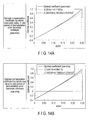
- FIGS. 11A and 11B are figures for explaining an amplitude ratio estimated error with respect to the number of samples as specific examples of the embodiment
- FIGS. 12A and 12B are figures for explaining a rotation angle estimated error with respect to the number of samples as specific examples of the embodiment
- FIGS. 13A and 13B are figures for explaining a rotation angle estimated error with respect to the number of samples as specific examples of the embodiment
- FIGS. 14A , 14 B, 14 C and 14 D are figures for explaining an optimal compensation coefficient with respect to the amplitude ratio as specific examples of the embodiment
- FIGS. 15A , 15 B, 15 C and 15 D are figures for explaining an optimal compensation coefficient with respect to the amplitude ratio as specific examples of the embodiment
- FIGS. 16A , 16 B, 16 C and 16 D are figures for explaining an optimal compensation coefficient with respect to the amplitude ratio as specific examples of the embodiment
- FIG. 17 is a flowchart for explaining a procedure of servo demodulation processing according to the embodiment.
- FIGS. 18A , 18 B, 18 C, 18 D, 18 E, 18 F, 18 G, 18 H, 18 I, 18 J and 18 K are figures for explaining a specific example of update processing for the optimal compensation coefficient and the rotation compensation angle in the servo demodulation processing of the embodiment;
- FIGS. 19A , 19 B, 19 C, 19 D, 19 E, 19 F, 19 G, 19 H, 19 I, 19 J and 19 K are figures for explaining a specific example of the update processing for the optimal compensation coefficient and the rotation compensation angle in the servo demodulation processing of the embodiment.
- FIGS. 20A , 20 B, 20 C, 20 D, 20 E, 20 F, 20 G, 20 H, 20 I, 20 J and 20 K are figures for explaining a specific example of the update processing for the optimal compensation coefficient and the rotation compensation angle in the servo demodulation processing of the embodiment.
- a method for servo demodulation comprises generating a first demodulated signal and a second demodulated signal calculated from amplitude values of burst signal patterns in a first area and a second area, in order to generate a position error signal of a reader based on a servo pattern read from a disk by the reader. Further, the method for servo demodulation comprises calculating a square-root of sum of squares of the first and second demodulated signals, and calculating an optimal compensation coefficient of a linearity correction function to be used in the linearity compensation of the position error signal based on a maximum value and a minimum value of the square-root of sum of squares.
- FIG. 1 is a block diagram showing an essential part of a disk drive according to the present embodiment.
- the disk drive is comprised of a head-disk assembly (HDA), a head amplifier integrated circuit (hereinafter referred to as head amplifier IC) 11 , a system controller 15 , and a driver IC 18 .
- HDA head-disk assembly
- IC head amplifier integrated circuit
- the HDA comprises a disk 1 , which is a storage medium, a spindle motor (SPM) 2 , an arm 3 with a head 10 , and a voice coil motor (VCM) 4 .
- the disk 1 is rotated by the spindle motor 2 .
- the arm 3 and the VCM 4 constitute an actuator.
- the actuator controls the head 10 on the arm 3 to move to a designated position on the disk 1 by driving the VCM 4 .
- the driving of the VCM 4 is controlled by a driving current from the driver IC 18 .
- a large number of tracks are formed on the disk 1 .
- a plurality of servo areas servo wedges
- a data area between each of the servo areas are provided.
- a two-phase null servo pattern comprising first burst pattern (i.e., first burst signal pattern) N and second burst pattern (i.e., second burst signal pattern) Q is recorded as will be described later, wherein the burst patterns (i.e., burst signal patterns) in the adjacent tracks are mutually different in their phases with respect to a cross track direction.
- the head 10 comprises a reader (or read head) 10 R and a writer (or write head) 10 W.
- the reader 10 R reads the null servo pattern recorded in the servo area on the disk 1 . Further, the reader 10 R reads data recorded in the data area on the disk 1 .
- the writer 10 W writes data in the data area on the disk 1 .
- the head amplifier IC 11 amplifies a read signal (readback signal) read from the reader 10 R, and transmits the read signal (readback signal) to a read/write (R/W) channel 12 . Further, the head amplifier IC 11 supplies a write current according to write data output from the R/W channel 12 to the writer 10 W.
- the system controller 15 comprises a one-chip integrated circuit, and comprises the R/W channel 12 , a hard disk controller (HDC) 13 , a micro processor (MPU) 14 , and a user-defined logic circuit (user-defined logic [UDL]), which is not shown.
- the R/W channel 12 comprises a read channel 12 R and a write channel 12 W.
- the read channel 12 R executes demodulation processing of the read signal (output of the head amplifier IC 11 ) read from the reader 10 R.
- the write channel 12 W executes signal processing of the write data.
- the HDC 13 comprises an interface controller which controls data transfer between a host 19 and the R/W 12 .
- the HDC 13 controls a buffer memory (DRAM) 16 and a flash memory 17 , and reads or writes the data.
- DRAM buffer memory
- the MPU 14 is a micro-controller and constitutes a servo system which executes positioning control (servo control) of the head 10 by controlling the VCM 4 through the driver IC 18 . Further, the MPU 14 controls a read operation or a write operation of data on the disk 1 through the R/W channel 12 .
- FIG. 2 shows a configuration of the servo system accommodated in the disk drive of the present embodiment.
- the servo system is comprised of a servo burst demodulator 20 included in the read channel 12 R and the MPU 14 .
- the servo burst demodulator 20 demodulates the two-phase burst patterns N and Q included in the null servo pattern from the read signal (output of the head amplifier IC 11 ) read by the reader 10 R.
- the magnetization patterns in the cross track direction of burst patterns N and Q have a phase difference of 90 degrees with respect to each other.
- the MPU 14 controls the reader 10 R to be positioned at the target position of the track by using the position error signal (PES) demodulted based on burst patterns N and Q.
- the servo area (servo wedge) includes Gray codes indicating an address of that track. In the present embodiment, demodulation processing of the Gray codes is omitted.
- the servo burst demodulator 20 executes discrete Fourier transform (DFT) computation on a data sequence of the readback signal in a time domain, and outputs a demodulated signal as a result of the DFT computation.
- the real DFT in general refers to the operation of converting n items of time-series data into a total of n items of real data comprising (n/2 ⁇ 1) items of complex data of the first to (n/2 ⁇ 1) th order and the items of real data of order 0 and order n/2.
- the servo burst demodulator 20 of the present embodiment executes an arithmetic operation of obtaining only the complex data of one specific order (two items of real data). That is, the servo burst demodulator 20 outputs a demodulated signal 200 including a sine component and a cosine component of each of burst signals N and Q.
- the MPU 14 achieves the functions of executing each kind of processing of initial phase compensation 21 , rotation angle compensation 22 , velocity compensation 23 , and linearity compensation 24 with respect to the demodulated signal 200 output from the servo burst demodulator 20 by firmware.
- Each of the functions 21 to 24 achieved by the MPU 14 may be accomplished by a dedicated module embedded in the UDL as hardware instead of firmware.
- the MPU 14 performs rotation processing with respect to the demodulated signal 200 such that the data is parallel to the real axis or the imaginary axis on a complex plane. That is, processing is performed such that the demodulated signal 200 , which is the complex data, only has a real part or an imaginary part.
- the rotation angle compensation 22 the MPU 14 executes the processing of compensating a rotation angle as will be described later with respect to a corrected signal (real data) 201 obtained after the compensation by the initial phase compensation 21 .
- the MPU 14 executes processing for the corrected signal (real data) obtained after the compensation by the rotation angle compensation 22 such that a substantially elliptical shape of N vs Q Lissajous is corrected to a substantially circular shape.
- the linearity compensation 24 the MPU 14 performs the processing of compensating the linearity in regard to the actual change of position of the reader 10 R with respect to the change in the signal (real data) obtained after the compensation by the velocity compensation 23 , and outputting the position error signal (PES).
- the MPU 14 calculates an optimal compensation coefficient of the linearity correction function in the linearity compensation 24 . Further, the MPU 14 calculates an optimal rotation compensation angle to be used in the rotation angle compensation 22 , as will be described later. In addition, the MPU 14 executes update processing of the optimal compensation coefficient and the optimal rotation compensation angle.
- FIG. 3A shows an example of the change in the position of reader 10 R and the N and Q signals (signal 201 after the initial phase compensation) with respect to the relative postions in the cross track direction of the magnetization patterns
- FIG. 3B shows its Lissajous (N vs Q).
- N and Q have a phase of 90 degrees.
- the form of Lissajous of FIG. 3B is substantially square with rounded corners, and Lissajous has a rotation angle with respect to the N and Q-axes.
- PTP pole tip protrusion
- the PTP is a phenomenon in which a tip portion of the head 10 protrudes by heat.
- a distance between the reader 10 R and the surface of the disk 1 changes, in particular, and a servo demodulation result may be affected.
- FIGS. 3A and 3B are illustrations of the case where the PTP is 0.8.
- a Lissajous rotation angle is ⁇ 16.2 degrees and the amplitude ratio (a 3 /a 1 ) to be described later is 0.07.
- the rotation angle is ⁇ 5.4 degrees and the amplitude ratio (a 3 /a 1 ) is 0.04.
- the optimal compensation coefficient and the optimal rotation compensation angle deviate from the compensation coefficient and the rotation compensation angle which have been set. Accordingly, since the servo demodulation error (deviation) varies by the change in the PTP, it is desirable to update the optimal compensation coefficient and the rotation compensation angle. Hence, the MPU 14 of the present embodiment executes the processing of updating the optimal compensation coefficient and the rotation compensation angle in a relatively short time.
- coefficients a 1 , a 3 , a 5 , and a 7 correspond to amplitudes of the order 1, 3, 5, and 7 of an intensity change in the offset direction of N and Q, respectively.
- ⁇ 3 , ⁇ 5 , and ⁇ 7 correspond to a quarter of a phase of the third order with respect to the first order, a quarter of a phase of the fifth order with respect to the first order, and one eighth of a phase of the seventh order with respect to the first order, respectively.
- the range of ⁇ is ⁇ /4 ⁇ + ⁇ /4.
- N a 1 cos( ⁇ +(2 n+ 1) ⁇ /4) ⁇ a 3 cos(3(2 n+ 1) ⁇ /4 ⁇ ) (6)
- Q a 1 sin( ⁇ +(2 n+ 1) ⁇ /4)+ a 3 sin(3(2 n+ 1) ⁇ /4 ⁇ ) (7)
- Equations (6) and (7) can be rewritten as equations (8) to (19) below, by substituting 0 to 3 for n.
- N+Q + ⁇ square root over (2) ⁇ ( a 1 +a 3 )cos( ⁇ )
- N ⁇ Q ⁇ ⁇ square root over (2) ⁇ ( a 1 +a 3 )sin( ⁇ )
- Q/N +tan( ⁇ + ⁇ /4) (10)
- N + Q - 2 ⁇ ( a 1 + a 3 ) ⁇ sin ⁇ ( ⁇ )
- N - Q - 2 ⁇ ( a 1 + a 3 ) ⁇ cos ⁇ ( ⁇ )
- N / Q - tan ⁇ ( ⁇ + ⁇ 4 ) ( 13 )
- , or S4 (N+Q)/(N ⁇ Q) in the other conditions.
- Equations (22) and (23) can be rewritten as equations (24) to (31) below, by substituting 0 to 3 for n.
- the output 201 by the initial phase compensation function 21 at position x of the reader 10 R can be expressed as generalized formulae as shown in equations (1) and (2), and as simplified formulae as shown in equations (3) and (4).
- the MPU 14 calculates the maximum value (S2MAX) 2 and the minimum value (S2MIN) 2 of the samples from the value of sum of squares (S2 2 ). That is, the maximum value (S2MAX) 2 is the maximum value (a 1 +a 3 ) 2 , and the minimum value (S2MIN) 2 is the minimum value (a 1 ⁇ a 3 ) 2 described above in connection with the above equation (5).
- the MPU 14 outputs the position error signal (PES) by compensating the linearity with respect to the actual position change of the reader 10 R by the function of the linearity compensation 24 .
- the MPU 14 calculates the optimal compensation coefficient of the linearity correction function in the linearity compensation 24 .
- the MPU 14 can update the optimal compensation coefficient based on the amplitude ratio a 3 /a 1 according to the change in the maximum value and the minimum value of the sum of squares. Further, the amplitude ratio a 3 /a 1 means a ratio of the third-order component amplitude a 3 to the first-order component amplitude a 1 . Further, by updating S3 when updating the maximum value, the MPU 14 can determine and update the rotation compensation angle ⁇ from
- the head 10 surely passes the points of S2MAX and S2MIN while it moves a distance more than a quarter of a magnetization pattern period in the cross track direction. Therefore, if the sampling point when the head 10 passes is close to these points, the MPU 14 can obtain a value close to S2MAX and a value close to S2MIN.
- the head 10 is seeking, the head 10 passes through many magnetization patterns, and if a virtual track control (i.e. a virtual circle control) is used, the head 10 crosses many magnetization patterns when the head 10 is on the track. Further, some movement occurs even after a head switching operation, and in a settled state after a seek, the head 10 travels more than a quarter of the magnetization pattern relatively slowly. Therefore, it is easy for the MPU 14 to find S2MAX and S2MIN.
- a virtual track control i.e. a virtual circle control
- the MPU 14 should preferably execute several search sets, remove extreme values from the values obtained in each of the search sets, and update the optimal compensation coefficient by using a median and an average value as well.
- FIGS. 4A to 20K will now be described specifically over the principle description of the present embodiment given above.
- FIGS. 4A and 4B show specific examples of the cases where Gaussian noise (additive white Gaussian noise [AWGN]) is superimposed on the N and Q signals with respect to position x which changes randomly where the amplitude ratio a 3 /a 1 is 0.1, as the probability density of S2MAX and S2MIN.
- Gaussian noise additive white Gaussian noise [AWGN]
- S2MAX is true value 1.1
- S2MIN is true value 0.9
- S2MAX is a value less than or equal to true value 1.1
- S2MIN is a value greater than or equal to true value 0.9.
- the larger the number of samples n is the higher the probability density of S2MAX and S2MIN is at the true values.
- S2MAX and S2MIN distribute over and below the true values. The larger the noise is and the larger the number of samples n is, the more the peak of the probability density is away from the true values.
- FIGS. 6A to 6F and FIGS. 7A to 7F are specific examples showing changes in the measured values of S2MAX and S2MIN with respect to the noise.
- FIGS. 6A to 6F show the specific examples of the case where the amplitude ratio a 3 /a 1 is 0.05
- FIGS. 7A to 7F show the specific examples of the case where the amplitude ratio a 3 /a 1 is 0.10.
- FIGS. 6A , 7 A is the figure showing the average values of S2MAX and S2MIN.
- FIGS. 6B and 7B errors of the average values of S2MAX and S2MIN from the true values vary substantially linearly with respect to the noise.
- FIGS. 6D and 7D are the figures in which the amplitude ratio a 3 /a 1 is calculated from the average values of S2MAX and S2MIN, and errors from the average values are plotted by filled circles.
- FIGS. 6C and 7C a standard deviation of S2MAX and S2MIN also varies substantially linearly with respect to the noise. From these matters, as shown in FIGS.
- the errors which have been plotted by the filled circles are corrected with the correction linear function, and those corrected errors are plotted by open circles. That is, the estimated errors are substantially zero.
- the correction linear function expression differs according to the number of samples n, and the plotting which has been corrected with the correction linear function differs according to the amplitude ratio a 3 /a 1 .
- FIGS. 9A and 9B are the figures which show compensation coefficients a and b with respect to the amplitude ratio a 3 /a 1 in the correction linear function.
- compensation coefficient a can be substantially approximated by a quadratic function with respect to the amplitude ratio a3/a 1 .
- compensation coefficient b can be substantially approximated by a linear function with respect to the amplitude ratio a 3 /a 1 .
- FIG. 10 shows an example of coefficients (a0, a1, a2, b0, b1) in an approximate expression regarding compensation coefficient a, b according to the value of N in the correction linear function.
- FIGS. 8A to 8F are specific examples showing changes in the observed values of S4, S5 with respect to noise. As shown in FIGS. 5A , 5 B and FIGS. 8A to 8F , a peak of the probability density is not away from the true value.
- FIGS. 11A and 11B are the figures showing an estimated error of the amplitude ratio a 3 /a 1 with respect to the number of samples.
- the total number of samples is the product of the number of samples n of an inner loop and the repeat count m of an outer loop in the flowchart of FIG. 17 to be described later. As shown in FIGS.
- FIGS. 12A and 12B are the figures showing an estimated error of the rotation angle by S4 with respect to sample count n.
- the optimal compensation coefficient of the linearity correction function to be applied based on the estimated value can be calculated.
- FIGS. 14A to 14D show an example of a calculation result of the optimal compensation coefficient with respect to the amplitude ratio a 3 /a 1 when the linearity correction function “(1 ⁇ G m ) ⁇ r+G m ⁇ r 2 ” described in United States Patent Application US2012/0293885 is applied.
- G m is the optimal compensation coefficient
- r indicates
- 15A to 15D show an example of a calculation result of the optimal compensation coefficient with respect to the amplitude ratio a 3 /a 1 when the linearity correction function “ ⁇ N/(
- ⁇ is the optimal compensation coefficient
- N and Q are readback signal amplitude values corresponding to the null burst patterns N and Q, respectively.
- FIGS. 18A to 18K is the figure for explaining a specific example of a process for updating the optimal compensation coefficient and the rotation compensation angle in real time by the above-mentioned steps.
- the MPU 14 sets an initial value regarding S2MAX and S2MIN, which are the square roots of the maximum value and the minimum value within the number of samples n calculated from the sum of squares (S2 2 ) described above (block 300 ). Further, the MPU 14 acquires demodulated N and Q which are read from the servo area (servo wedge) (block 301 ). N and Q are readback signal amplitude values (refer to equations (1) to (4) described above).
- the MPU 14 executes the processing of acquiring the maximum value S2MAX and the minimum value S2MIN of the number of samples n (block 302 ).
- the MPU 14 repeats the processing shown in block 302 m times, and calculates the average value (S2MAX_AVE, S2MIN_AVE) and the standard deviation (S2MAX_STD, S2MIN_STD) (block 303 ).
- S2X and S2N are constants for securing the effective digit of variables to be used in obtaining the standard deviation.
- the MPU 14 carries out the operation as shown in the following equations (34) and (35) based on the average value and the standard deviation calculated by the processing of block 303 (block 304 ):
- a 31AVE ( S 2MAX_AVE ⁇ S 2MIN_AVE)/( S 2MAX_AVE +S 2MIN_AVE) (34)
- a 31STD ( S 2MAX_STD+ S 2MIN_STD)/( S 2MAX_AVE +S 2MIN_AVE) (35)
- equation 35 may be rewritten as shown in the following equation (36) or (37):
- a 31STD 2 ⁇ S 2MAX_STD/( S 2MAX_AVE+ S 2MIN_AVE) (36)
- a 31STD 2 ⁇ S 2MIN_STD/( S 2MAX_AVE+ S 2MIN_AVE) (37)
- , or S4
- in any other conditions, as described above. The MPU 14 then averages S4 of the aforementioned conditions m times, and can update the rotation compensation angle ⁇ from the relation with the averaged S4, which is ⁇ arctan(S4) (block 307 ).
- FIGS. 18A to 18K relate to the case of the combination of the magnetization pattern on the disk 1 and the read head 10 R.
- the magnetization pattern has the characteristics that an average value of the amplitude ratio a 3 /a 1 is 0.10, an average rotation angle is 20 degrees, and a pitch non-uniformity is 5% rms.
- FIGS. 19A to 19K are the examples of the case where the virtual circle amplitude is as small as 1.0. In this case, since the travel distance is small with n sample, detection of S2MAX and S2MIN is insufficient. Thus, the estimated amplitude ratio a 3 /a 1 is deviated a little, and there is a section in which the demodulation error is somewhat large.
- FIGS. 20A to 20K are the same those of FIGS. 19A to 19K in that the virtual circle amplitude is 1.0, but the displacement disturbance is as large as 0.25. Therefore, a detection frequency of S2MAX and S2MIN is high and the demodulation error is relatively small.
- the optimal compensation coefficient and the rotation compensation angle should be stored for each zone, and the update processing should be performed for each zone.
- determination and averaging of S2MAX and S2MIN do not necessarily have to be performed in continuous sampling. That is, alternatively, it is possible to perform the sampling when returning to the zone after moving to a different zone and continue the update processing.
- the update processing if previously obtained optimal compensation coefficient and rotation compensation angle are utilized by adding a weight to each of those values in addition to newly obtained optimal compensation coefficient and rotation compensation angle, the accuracy can be enhanced as time passes.
- N_offset (N+(k ⁇ 1) ⁇ N_offset)/k”
- Q_offset (Q+(k ⁇ 1) ⁇ Q_offset)/k” with smoothing coefficient 1/k
- N_offset and Q_offset may be updated to correct the offsets of N and Q.
- k should be set to a number which is greater than the number of samples of several tracks.
- the method and the apparatus as claimed enable reducing adjustment in a manufacturing process of a disk drive and preventon of lowering the performance of the disk drive in operation.
Abstract
Description
N(φ)=a 1 cos φ−a3 cos(3φ−4θ3)+a 5 cos(5φ−4θ5)−a 7 cos(7φ−8θ7)+ . . . . (1)
and
Q(φ)=a 1 sin φ+a 3 sin(3φ−4θ3)+a 5 sin(5φ−4θ5)+a 7 sin(7φ−8θ7)+ . . . . (2),
where φ is 2πx/X.
N=a 1 cos φ−a 3 cos(3φ−4θ) (3)
and
Q=a 1 sin φ+a 3 sin(3φ−4θ) (4),
where Lissajous rotation angle θ is θ3.
S22 =N 2 +Q 2 =a 1 2 +a 3 2−2a 1 a 3 cos(4φ−4θ) (5)
N=a 1 cos(θ+(2n+1)π/4)−a 3 cos(3(2n+1)π/4−θ) (6)
Q=a 1 sin(θ+(2n+1)π/4)+a 3 sin(3(2n+1)π/4−θ) (7)
N=a 1 cos(θ+π/4)−a 3 cos(3π/4−θ)=(a 1 +a 3)cos(θ+π/4) (8)
Q=a 1 sin(θ+π/4)+a 3 sin(3π/4−θ)=(a 1 +a 3)sin(θ+π/4) (9)
N+Q=+√{square root over (2)}(a 1 +a 3)cos(θ),N−Q=−√{square root over (2)}(a 1 +a 3)sin(θ),Q/N=+tan(θ+π/4) (10)
S4=tan(θ+π/4) (21)
N=a 1 cos φ−a 3 cos(3φ−4θ)=a 1 cos(θ+nπ/2)−a 3 cos(3nπ/2−θ) (22)
N=a 1 cos(θ)−a 3 cos(−θ)=(a 1 −a 3)cos(θ) (24)
Q=a 1 sin(θ)+a 3 sin(−θ)=(a 1 −a 3)sin(θ) (25)
N=a 1 cos(θ+π/2)−a 3 cos(3π/2−θ)=−(a 1 −a 3)sin(θ) (26)
Q=a 1 sin(θ+π/2)+a 3 sin(3π/2−θ)=(a 1 −a 3)cos(θ) (27)
N=a 1 cos(θ+π)−a 3 cos(3π−θ)=−(a 1 −a 3)cos(θ) (28)
Q=a 1 sin(θ+π)+a 3 sin(3π−θ)=−(a 1 −a 3)sin(θ) (29)
N=a 1 cos(θ+3π/2)−a 3 cos(9π/2−θ)=(a 1 −a 3)sin(θ) (30)
Q=a 1 sin(θ+3π/2)+a 3 sin(9π/2−θ)=−(a 1 −a 3)cos(θ) (31)
a 1=(S2MAX+S2MIN)/2 (32)
a 3=(S2MAX−S2MIN)/2 (33)
Further, by updating S4 when updating the maximum value, the rotation compensation angle θ can be determined and updated from θ=arctan(S4). In this case, the value of (a1+a3) is unnecessary. On the other hand, by updating S5 when updating the minimum value, it is possible to determine and update the rotation compensation angle θ from θ=arctan(S5). Also in this case, the value of (a1+a3) is unnecessary.
A31AVE=(S2MAX_AVE−S2MIN_AVE)/(S2MAX_AVE+S2MIN_AVE) (34)
A31STD=(S2MAX_STD+S2MIN_STD)/(S2MAX_AVE+S2MIN_AVE) (35)
A31STD=2×S2MAX_STD/(S2MAX_AVE+S2MIN_AVE) (36)
A31STD=2×S2MIN_STD/(S2MAX_AVE+S2MIN_AVE) (37)
Claims (18)
Priority Applications (1)
| Application Number | Priority Date | Filing Date | Title |
|---|---|---|---|
| US14/081,908 US8908303B1 (en) | 2013-07-30 | 2013-11-15 | Method for servo demodulation and disk storage apparatus |
Applications Claiming Priority (2)
| Application Number | Priority Date | Filing Date | Title |
|---|---|---|---|
| US201361859878P | 2013-07-30 | 2013-07-30 | |
| US14/081,908 US8908303B1 (en) | 2013-07-30 | 2013-11-15 | Method for servo demodulation and disk storage apparatus |
Publications (1)
| Publication Number | Publication Date |
|---|---|
| US8908303B1 true US8908303B1 (en) | 2014-12-09 |
Family
ID=52001681
Family Applications (1)
| Application Number | Title | Priority Date | Filing Date |
|---|---|---|---|
| US14/081,908 Expired - Fee Related US8908303B1 (en) | 2013-07-30 | 2013-11-15 | Method for servo demodulation and disk storage apparatus |
Country Status (1)
| Country | Link |
|---|---|
| US (1) | US8908303B1 (en) |
Cited By (2)
| Publication number | Priority date | Publication date | Assignee | Title |
|---|---|---|---|---|
| US20180343172A1 (en) * | 2014-09-11 | 2018-11-29 | Infoblox Inc. | Exponential moving maximum (emm) filter for predictive analytics in network reporting |
| US11094342B2 (en) * | 2019-07-23 | 2021-08-17 | Kabushiki Kaisha Toshiba | Disk device |
Citations (25)
| Publication number | Priority date | Publication date | Assignee | Title |
|---|---|---|---|---|
| US4549232A (en) | 1983-06-27 | 1985-10-22 | International Business Machines Corporation | Phase modulated servo system |
| JPH0765306A (en) | 1993-08-25 | 1995-03-10 | Toshiba Corp | Magnetic disk device and method for controlling bias current |
| JPH08249842A (en) | 1995-03-06 | 1996-09-27 | Hitachi Ltd | Head positioning method and magnetic disk device |
| US5689384A (en) | 1994-06-30 | 1997-11-18 | International Business Machines Corporation | Timing based servo system for magnetic tape systems |
| US6046879A (en) | 1996-05-16 | 2000-04-04 | Seagate Technology, Inc. | Weighted linearization of a position error signal in a disc drive |
| US6067204A (en) | 1996-06-03 | 2000-05-23 | Seagate Technology, Inc. | Disc drive servo pattern insensitive to read head |
| US6078460A (en) | 1997-07-25 | 2000-06-20 | Kabushiki Kaisha Toshiba | Head positioning control system for use in a disk drive |
| JP2001110027A (en) | 1999-10-08 | 2001-04-20 | Hitachi Ltd | Magnetic storage |
| US20040080863A1 (en) | 2002-10-24 | 2004-04-29 | Shinsuke Nakagawa | Positioning control device |
| US6853514B2 (en) | 2002-02-05 | 2005-02-08 | Seagate Technology Llc | Method for measuring PES noise of servo patterned media |
| JP2006309843A (en) | 2005-04-27 | 2006-11-09 | Toshiba Corp | Disk drive and servo control method |
| US7209314B2 (en) | 2005-06-09 | 2007-04-24 | Hitachi Global Storage Technologies Netherlands B.V. | Disk drive with phase-quadrature servo pattern and demodulated position error signal insensitive to timing and phase-misalignment errors |
| US7430082B2 (en) | 2001-06-28 | 2008-09-30 | Stmicroelectronics, Inc. | Circuit and method for demodulating a servo position burst |
| US7440224B2 (en) | 2006-01-23 | 2008-10-21 | Toshiba Corporation | Disk drive servo |
| WO2008139603A1 (en) | 2007-05-14 | 2008-11-20 | Fujitsu Limited | Storage device, head position detecting method, and control circuit |
| US7457066B2 (en) | 2006-05-31 | 2008-11-25 | Kabushiki Kiasha Toshiba | Method and apparatus for phase-shift null-burst-pattern |
| US7529059B2 (en) | 2006-03-10 | 2009-05-05 | Broadcom Corporation | Method for determining read/write head position based on phase detection of a servo pattern |
| JP2009110597A (en) | 2007-10-30 | 2009-05-21 | Hitachi Global Storage Technologies Netherlands Bv | Disk drive and controlling method thereof |
| JP2010049742A (en) | 2008-08-21 | 2010-03-04 | Hitachi Global Storage Technologies Netherlands Bv | Method and apparatus for positioning magnetic head |
| US7859778B1 (en) | 2008-02-21 | 2010-12-28 | Seagate Technology Llc | Deterministic phase mismatch correction in servo position estimation systems |
| US8077428B1 (en) * | 2010-06-23 | 2011-12-13 | Western Digital Technologies, Inc. | Disk drive correcting position error signal based on velocity of head |
| US8295002B1 (en) | 2009-10-12 | 2012-10-23 | Marvell International Ltd. | Null servo demodulation for short servo wedge in disk storage systems |
| JP2012205594A (en) | 2004-08-23 | 2012-10-25 | Sylentis Sau | TREATMENT OF EYE DISORDER CHARACTERIZED BY ELEVATED INTRAOCULAR PRESSURE BY siRNA |
| US20120293885A1 (en) | 2011-05-20 | 2012-11-22 | Kabushiki Kaisha Toshiba | Position demodulator and position demodulation method |
| US20140078614A1 (en) | 2012-09-19 | 2014-03-20 | Kabushiki Kaisha Toshiba | Magnetic disk device and demodulation position correcting method |
-
2013
- 2013-11-15 US US14/081,908 patent/US8908303B1/en not_active Expired - Fee Related
Patent Citations (37)
| Publication number | Priority date | Publication date | Assignee | Title |
|---|---|---|---|---|
| US4549232A (en) | 1983-06-27 | 1985-10-22 | International Business Machines Corporation | Phase modulated servo system |
| JPH0765306A (en) | 1993-08-25 | 1995-03-10 | Toshiba Corp | Magnetic disk device and method for controlling bias current |
| US5689384A (en) | 1994-06-30 | 1997-11-18 | International Business Machines Corporation | Timing based servo system for magnetic tape systems |
| JPH08249842A (en) | 1995-03-06 | 1996-09-27 | Hitachi Ltd | Head positioning method and magnetic disk device |
| US6046879A (en) | 1996-05-16 | 2000-04-04 | Seagate Technology, Inc. | Weighted linearization of a position error signal in a disc drive |
| JP2000514585A (en) | 1996-05-16 | 2000-10-31 | シーゲート テクノロジー,インコーポレイテッド | Weighted linearization of disk drive position error signal |
| US6067204A (en) | 1996-06-03 | 2000-05-23 | Seagate Technology, Inc. | Disc drive servo pattern insensitive to read head |
| US6078460A (en) | 1997-07-25 | 2000-06-20 | Kabushiki Kaisha Toshiba | Head positioning control system for use in a disk drive |
| JP2001110027A (en) | 1999-10-08 | 2001-04-20 | Hitachi Ltd | Magnetic storage |
| US6590729B1 (en) | 1999-10-08 | 2003-07-08 | Hitachi, Ltd. | Magnetic disk drive with servo signal decoder using amplitude detection and phase detection system |
| US7430082B2 (en) | 2001-06-28 | 2008-09-30 | Stmicroelectronics, Inc. | Circuit and method for demodulating a servo position burst |
| US6853514B2 (en) | 2002-02-05 | 2005-02-08 | Seagate Technology Llc | Method for measuring PES noise of servo patterned media |
| US20040080863A1 (en) | 2002-10-24 | 2004-04-29 | Shinsuke Nakagawa | Positioning control device |
| JP2004145968A (en) | 2002-10-24 | 2004-05-20 | Hitachi Ltd | Positioning controller |
| US6922304B2 (en) | 2002-10-24 | 2005-07-26 | Hitachi, Ltd. | Positioning control device |
| JP2012205594A (en) | 2004-08-23 | 2012-10-25 | Sylentis Sau | TREATMENT OF EYE DISORDER CHARACTERIZED BY ELEVATED INTRAOCULAR PRESSURE BY siRNA |
| JP2006309843A (en) | 2005-04-27 | 2006-11-09 | Toshiba Corp | Disk drive and servo control method |
| US7312946B2 (en) | 2005-04-27 | 2007-12-25 | Kabushiki Kaisha Toshiba | Method and apparatus for servo control in a disk drive |
| US7209314B2 (en) | 2005-06-09 | 2007-04-24 | Hitachi Global Storage Technologies Netherlands B.V. | Disk drive with phase-quadrature servo pattern and demodulated position error signal insensitive to timing and phase-misalignment errors |
| US7440224B2 (en) | 2006-01-23 | 2008-10-21 | Toshiba Corporation | Disk drive servo |
| US7529059B2 (en) | 2006-03-10 | 2009-05-05 | Broadcom Corporation | Method for determining read/write head position based on phase detection of a servo pattern |
| US20090040641A1 (en) | 2006-05-31 | 2009-02-12 | Kabushiki Kaisha Toshiba | Method and apparatus for phase-shift null-burst-pattern |
| US7457066B2 (en) | 2006-05-31 | 2008-11-25 | Kabushiki Kiasha Toshiba | Method and apparatus for phase-shift null-burst-pattern |
| US8023219B2 (en) | 2007-05-14 | 2011-09-20 | Toshiba Storage Device Corporation | Storage device, head position detection method and control circuit |
| WO2008139603A1 (en) | 2007-05-14 | 2008-11-20 | Fujitsu Limited | Storage device, head position detecting method, and control circuit |
| JP2009110597A (en) | 2007-10-30 | 2009-05-21 | Hitachi Global Storage Technologies Netherlands Bv | Disk drive and controlling method thereof |
| US7859787B2 (en) | 2007-10-30 | 2010-12-28 | Hitachi Global Storage Technologies, Netherlands, B.V. | Disk drive and controlling method thereof |
| US7859778B1 (en) | 2008-02-21 | 2010-12-28 | Seagate Technology Llc | Deterministic phase mismatch correction in servo position estimation systems |
| JP2010049742A (en) | 2008-08-21 | 2010-03-04 | Hitachi Global Storage Technologies Netherlands Bv | Method and apparatus for positioning magnetic head |
| US20110063751A1 (en) | 2008-08-21 | 2011-03-17 | Kei Yasuna | Method and apparatus for positioning a magnetic-recording head |
| US8295002B1 (en) | 2009-10-12 | 2012-10-23 | Marvell International Ltd. | Null servo demodulation for short servo wedge in disk storage systems |
| US8077428B1 (en) * | 2010-06-23 | 2011-12-13 | Western Digital Technologies, Inc. | Disk drive correcting position error signal based on velocity of head |
| US20120293885A1 (en) | 2011-05-20 | 2012-11-22 | Kabushiki Kaisha Toshiba | Position demodulator and position demodulation method |
| JP2012243367A (en) | 2011-05-20 | 2012-12-10 | Toshiba Corp | Position demodulating device and position demodulating method |
| US8625230B2 (en) | 2011-05-20 | 2014-01-07 | Kabushiki Kaisha Toshiba | Position demodulator and position demodulation method |
| US20140078614A1 (en) | 2012-09-19 | 2014-03-20 | Kabushiki Kaisha Toshiba | Magnetic disk device and demodulation position correcting method |
| JP2014059932A (en) | 2012-09-19 | 2014-04-03 | Toshiba Corp | Magnetic disk device, and demodulation position correction method |
Non-Patent Citations (4)
| Title |
|---|
| U.S. Appl. No. 13/578,781, filed Feb. 4, 2013, K.K. Toshiba. |
| U.S. Appl. No. 14/018,212, filed Sep. 4, 2013, K.K. Toshiba. |
| U.S. Appl. No. 14/194,482, filed Feb. 28, 2014, Kabushiki Kaisha Toshiba. |
| U.S. Appl. No. 61/822,565, filed May 13, 2013, Yamada. |
Cited By (3)
| Publication number | Priority date | Publication date | Assignee | Title |
|---|---|---|---|---|
| US20180343172A1 (en) * | 2014-09-11 | 2018-11-29 | Infoblox Inc. | Exponential moving maximum (emm) filter for predictive analytics in network reporting |
| US11153176B2 (en) * | 2014-09-11 | 2021-10-19 | Infoblox Inc. | Exponential moving maximum (EMM) filter for predictive analytics in network reporting |
| US11094342B2 (en) * | 2019-07-23 | 2021-08-17 | Kabushiki Kaisha Toshiba | Disk device |
Similar Documents
| Publication | Publication Date | Title |
|---|---|---|
| US8531798B1 (en) | Disk drive adjusting servo burst signals to compensate for radial velocity of the head | |
| US9514775B2 (en) | Reducing effect of frequency acquisition error in a position error signal responsive to split servo burst patterns | |
| US7848040B2 (en) | Magnetic recording disk and disk drive with amplitude-type servo fields having patterned alternating-polarity servo islands for read/write head positioning | |
| US7729073B2 (en) | Magnetic recording disk and disk drive with amplitude-type servo fields having patterned servo islands for read/write head positioning | |
| US7612961B2 (en) | Magnetic recording disk and disk drive with patterned phase-type servo fields for read/write head positioning | |
| US8605381B2 (en) | Systems and methods for phase compensated harmonic sensing in fly height control | |
| US8964325B1 (en) | Magnetic disk device and method for read/write offset error correction | |
| US9311937B2 (en) | Systems and methods for calibrating read and write operations in two dimensional magnetic recording | |
| US7312946B2 (en) | Method and apparatus for servo control in a disk drive | |
| US7292402B2 (en) | Systems and methods for multipass servowriting with a null burst pattern | |
| US7355810B2 (en) | Disk drive having a disk medium with discrete track | |
| US20020039247A1 (en) | Track pitch correction method and apparatus | |
| US20100053800A1 (en) | Phase detector that compensates for frequency variation induced bias in phases of servo burst fields | |
| US10748569B1 (en) | Magnetic disk device and method for demodulating servo demodulation position | |
| US7859778B1 (en) | Deterministic phase mismatch correction in servo position estimation systems | |
| US6404576B1 (en) | Method and system for compensation of nonlinearity or fluctuation of head-position signal | |
| US8848303B1 (en) | Disk storage apparatus and method for servo demodulation | |
| US8023219B2 (en) | Storage device, head position detection method and control circuit | |
| US7009805B2 (en) | Detection of track misregistration within user data channel | |
| US7835105B1 (en) | Propagation self servo write system and method for storage devices employing sector-servo scheme | |
| US8908303B1 (en) | Method for servo demodulation and disk storage apparatus | |
| US7848039B2 (en) | Magnetic recording disk and disk drive with patterned phase-type servo fields for read/write head positioning | |
| US7589929B2 (en) | Servo pattern writing apparatus, servo pattern writing method, servo pattern reading apparatus, and servo pattern reading method | |
| US9230584B1 (en) | Position demodulation apparatus and position demodulation method | |
| US7116511B2 (en) | Systems and methods for two-step reference pattern self-servowriting |
Legal Events
| Date | Code | Title | Description |
|---|---|---|---|
| AS | Assignment |
Owner name: KABUSHIKI KAISHA TOSHIBA, JAPAN Free format text: ASSIGNMENT OF ASSIGNORS INTEREST;ASSIGNOR:YAMADA, TOMOYOSHI;REEL/FRAME:031620/0220 Effective date: 20131105 |
|
| FEPP | Fee payment procedure |
Free format text: PAYOR NUMBER ASSIGNED (ORIGINAL EVENT CODE: ASPN); ENTITY STATUS OF PATENT OWNER: LARGE ENTITY |
|
| FEPP | Fee payment procedure |
Free format text: MAINTENANCE FEE REMINDER MAILED (ORIGINAL EVENT CODE: REM.) |
|
| LAPS | Lapse for failure to pay maintenance fees |
Free format text: PATENT EXPIRED FOR FAILURE TO PAY MAINTENANCE FEES (ORIGINAL EVENT CODE: EXP.); ENTITY STATUS OF PATENT OWNER: LARGE ENTITY |
|
| STCH | Information on status: patent discontinuation |
Free format text: PATENT EXPIRED DUE TO NONPAYMENT OF MAINTENANCE FEES UNDER 37 CFR 1.362 |
|
| FP | Lapsed due to failure to pay maintenance fee |
Effective date: 20181209 |