US9448280B2 - Circuit test system and method using a wideband multi-tone test signal - Google Patents
Circuit test system and method using a wideband multi-tone test signal Download PDFInfo
- Publication number
- US9448280B2 US9448280B2 US13/407,811 US201213407811A US9448280B2 US 9448280 B2 US9448280 B2 US 9448280B2 US 201213407811 A US201213407811 A US 201213407811A US 9448280 B2 US9448280 B2 US 9448280B2
- Authority
- US
- United States
- Prior art keywords
- test signal
- wideband
- test
- tones
- analog
- Prior art date
- Legal status (The legal status is an assumption and is not a legal conclusion. Google has not performed a legal analysis and makes no representation as to the accuracy of the status listed.)
- Expired - Fee Related, expires
Links
Images


Classifications
-
- G—PHYSICS
- G01—MEASURING; TESTING
- G01R—MEASURING ELECTRIC VARIABLES; MEASURING MAGNETIC VARIABLES
- G01R31/00—Arrangements for testing electric properties; Arrangements for locating electric faults; Arrangements for electrical testing characterised by what is being tested not provided for elsewhere
- G01R31/28—Testing of electronic circuits, e.g. by signal tracer
- G01R31/3167—Testing of combined analog and digital circuits
-
- G—PHYSICS
- G01—MEASURING; TESTING
- G01R—MEASURING ELECTRIC VARIABLES; MEASURING MAGNETIC VARIABLES
- G01R31/00—Arrangements for testing electric properties; Arrangements for locating electric faults; Arrangements for electrical testing characterised by what is being tested not provided for elsewhere
- G01R31/28—Testing of electronic circuits, e.g. by signal tracer
- G01R31/2832—Specific tests of electronic circuits not provided for elsewhere
- G01R31/2836—Fault-finding or characterising
- G01R31/2837—Characterising or performance testing, e.g. of frequency response
Definitions
- the embodiments disclosed herein relate to circuit testing and, more specifically, to a circuit test system and method using a wideband multi-tone test signal.
- a circuit testing system and an associated method that incorporate a programmable test signal generator capable of generating a test signal that has multiple tones uniformly distributed across a wideband with a specific bandwidth such that adjacent tones are all separated by a same frequency spacing.
- This test signal can be generated based on at least one user-specified test signal parameter and using, for example, an orthogonal frequency-division multiplexing (OFDM) spread spectrum technique.
- OFDM orthogonal frequency-division multiplexing
- this test signal can be processed (e.g., converted from digital to analog or shifted to a different wideband having the same bandwidth), as necessary, so that it is suitable for application to the specific device under test and so that the tones account for the full range of frequencies with the wideband operation of that device under test.
- the multi-tone test signal can be applied to the device under test and the output signal from the device under test can be captured.
- the resulting output signal can be processed, as necessary (e.g., converted back to digital or shifted back to the initial wideband) and then analyzed.
- the tones of this output signal can be analyzed in order to determine the various frequency responses associated with each of the tones. Consequently, the embodiments allow the full frequency bandwidth of the device under test to be characterized in a minimal amount of time and without a significant increase in hardware.
- the embodiments of the testing system can comprise at least a programmable test signal generator, a device under test and an analyzer.
- the programmable test signal generator can generate a test signal, based on one or more user-specified test signal parameters (e.g., a user-specified wideband, a user-specified number of tones, and/or a user-specified amount of spacing between adjacent tones) such that the resulting test signal has multiple tones, which are uniformly distributed across a wideband having a specific bandwidth.
- This can be accomplished, for example, by using an orthogonal frequency-division multiplexing (OFDM) spread spectrum technique and, particularly, by performing an inverse Fourier transform (IFT) operation.
- OFDM orthogonal frequency-division multiplexing
- IFT inverse Fourier transform
- the device under test can process the multi-tone test signal and, in response to the multi-tone test signal, can output an output signal.
- the analyzer can analyze the output signal and, particularly, the tones thereof (e.g., by performing a discrete Fourier transform (DFT) operation on the output signal) in order to determine the various frequency responses associated with each of the tones.
- DFT discrete Fourier transform
- One embodiment of the circuit testing system can further comprise additional components that can process the test and output signals, as necessary, to accommodate testing of an analog device as opposed to a digital device.
- one embodiment of the testing system can comprise a programmable test signal generator, a digital-to-analog converter, an analog device under test, an analog-to-digital converter and an analyzer.
- the programmable test signal generator can generate a digital test signal, based on one or more user-specified test signal parameters (e.g., a user-specified wideband, a user-specified number of tones, and/or a user-specified amount of spacing between adjacent tones).
- This digital test signal can have a specific number of tones uniformly distributed across a wideband having a specific bandwidth and can be generated in the same manner as discussed above (e.g., by using an orthogonal frequency-division multiplexing (OFDM) spread spectrum technique and, particularly, by performing an inverse Fourier transform (IFT) operation).
- the digital-to-analog converter can convert the digital test signal into an analog test signal.
- the analog device under test can process the analog test signal and, in response to the analog test signal, can output an analog output signal.
- the analog-to-digital converter can then convert the analog output signal into a digital output signal.
- the analyzer can analyze the digital output signal and, particularly, the tones thereof in the same manner as discussed above (e.g., by performing a discrete Fourier transform (DFT) operation on the digital output signal) in order to determine the various frequency responses associated with each of the tones.
- DFT discrete Fourier transform
- the method embodiments can comprise generating a test signal, based on one or more user-specified test signal parameters (e.g., a user-specified wideband, a user-specified number of carriers, and/or a user-specified amount of spacing between adjacent tones) such that the resulting test signal has multiple tones, which are uniformly distributed across a wideband with a specific bandwidth.
- This can be accomplished, for example, by using an orthogonal frequency-division multiplexing (OFDM) spread spectrum technique and, particularly, by performing an inverse Fourier transform (IFT) operation.
- OFDM orthogonal frequency-division multiplexing
- IFT inverse Fourier transform
- the multi-tone test signal can be applied to the device under test, which processes it and, in response, outputs an output signal.
- the output signal and, particularly, the tones thereof can be analyzed (e.g., by performing a discrete Fourier transform (DFT) operation on the output signal) in order to determine the various frequency responses associated with each
- One embodiment of the circuit testing method can further comprise performing additional processes on the test and output signals, as necessary, to accommodate testing of an analog device as opposed to a digital device.
- one embodiment of the circuit testing method can comprise performing generating, based on one or more user-specified test signal parameters, a digital test signal.
- This digital test signal can have a specific number of tones uniformly distributed across a wideband having a specific bandwidth and can be generated in the same manner as discussed above (e.g., by using an orthogonal frequency-division multiplexing (OFDM) spread spectrum technique and, particularly, by performing an inverse Fourier transform (IFT) operation).
- OFDM orthogonal frequency-division multiplexing
- IFT inverse Fourier transform
- the analog test signal can then be applied to the device under test, which process it and outputs an analog output signal.
- the analog output signal can then be converted into a digital output signal.
- the digital output signal and, particularly, the tones thereof can be analyzed in the same manner as discussed above (e.g., by performing a discrete Fourier transform (DFT) operation on the output signal) in order to determine the various frequency responses associated with each of the tones.
- DFT discrete Fourier transform
- FIG. 1 is a schematic diagram illustrating an embodiment of a circuit testing system
- FIG. 2 is a graph illustrating the frequency (f) to power spectral density (PSD) of an exemplary test signal
- FIG. 3 illustrates testing of a first device under test by the circuit testing system of FIG. 1 ;
- FIG. 4 illustrates testing of a second device under test by the circuit testing system of FIG. 1 ;
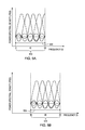
- FIG. 5A is a graph illustrating the frequency (f) to power spectral density (PSD) of an exemplary test signal
- FIG. 5B is a graph illustrating a shift in the frequency (f) to power spectral density (PSD) graph of FIG. 5A ;
- FIG. 6 is a flow diagram illustrating an embodiment of a circuit testing method.
- the integrated circuit components in wireless communication systems have wideband operation (i.e., operate at bandwidths of 500 kHz to 20 GHz) or ultra-wideband operation (i.e., operate at 20 GHz and beyond). Consequently, in order to accurately test such integrated circuit components, the frequency response must be characterized across the full frequency bandwidth (i.e., across the full range of operating frequencies within the wideband). Unfortunately, characterizing the frequency response across the full frequency bandwidth of a circuit component can be costly in terms of total testing time required and/or additional hardware required.
- one technique for characterizing the frequency response across the full frequency bandwidth can employ a signal generator with single phase-locked loop (PLL) to output a test signal.
- the multi-tone test signal can be applied to the circuit component and the response can be measured.
- a frequency divider in the PLL can further be repeatedly adjusted in order to consecutively generate multiple test signals having different frequencies.
- the frequency response of the circuit component to each of these test signals can be measured.
- the full frequency bandwidth of the circuit component can be characterized.
- this technique is costly in terms of required testing time because the test signal at the different frequency points must be generated consecutively and because the frequency response of the integrate circuit component must be measured and examined at each frequency point individually. Thus, as the bandwidth and/or the number of frequency points increases so does the required testing time.
- Another technique for characterizing the frequency response across the frequency bandwidth can use multiple different phase-locked loops (PLLs) to simultaneously generate multiple tone signals having different frequencies. These multiple tone signals can be applied to the circuit component simultaneously and the frequency response of the circuit component can be measured and characterized. While the testing time is reduced with this technique because the test signals at the different frequency points are generated and applied to the circuit component simultaneously, it is costly in terms of the required additional hardware (i.e., the multiple PLLs) to produce the multiple test signals at the different frequency points.
- PLLs phase-locked loops
- a circuit testing system and an associated method that incorporate a programmable test signal generator capable of generating a test signal that has multiple tones uniformly distributed across a wideband with a specific bandwidth such that adjacent tones are all separated by a same frequency spacing.
- This test signal can be generated based on at least one user-specified test signal parameter and using, for example, an orthogonal frequency-division multiplexing (OFDM) spread spectrum technique.
- OFDM orthogonal frequency-division multiplexing
- this test signal can be processed (e.g., converted from digital to analog or shifted to a different wideband having the same bandwidth), as necessary, so that it is suitable for application to the specific device under test and so that the tones account for the full range of frequencies with the wideband operation of that device under test.
- the multi-tone test signal can be applied to the device under test and the output signal from the device under test can be captured.
- the resulting output signal can be processed, as necessary (e.g., converted back to digital or shifted back to the initial wideband) and then analyzed.
- the tones of this output signal can be analyzed in order to determine the various frequency responses associated with each of the tones. Consequently, the embodiments allow the full frequency bandwidth of the device under test to be characterized in a minimal amount of time and without a significant increase in hardware.
- This testing system 100 can comprise at least a device under test 150 , a programmable test signal generator 120 with a user interface device 110 and an analyzer 180 .
- the device under test 150 can comprise a component of a circuit with wideband (i.e., at bandwidths of 500 kHz to 20 GHz) or ultra-wideband (i.e., 20 GHz and beyond) operation.
- the device under test 150 can, for example, comprise a band-pass filter, such as a low band-pass finite impulse response (FIR) filter that blocks relatively high frequencies or a high band-pass filter that blocks relatively low frequencies.
- FIR finite impulse response
- the user interface device 110 can receive, from a user, one or more test signal parameters for a desired multi-tone test signal (i.e., a multi-subcarrier test signal or a frequency agile test signal).
- test signal parameters may vary depending upon the type of device under test and the desired performance parameters thereof.
- these test signal parameters can comprise a user-specified wideband (i.e., a user specified range of frequencies), a user-specified number of tones, and/or a user-specified amount of spacing between adjacent tones so that the tones within the multi-tone test signal will account for the full range of frequencies with the wideband operation of that device under test.
- a wideband is a specific range of operating frequencies and the bandwidth of the wideband is the difference between the highest and lowest frequencies in that range.
- the programmable test signal generator 120 can generate (i.e., can be adapted to generate, configured to generate, programmed to generate, etc.) a test signal and, particularly, a digital test signal, based on the user-specified test signal parameters such that the resulting test signal has a multiple tones (i.e., has multiple subcarriers), which are uniformly distributed across a wideband having a specific bandwidth.
- FIG. 2 is a graph illustrating the frequency (f) (e.g., as measured in Hertz (Hz)) to power spectral density (PSD) (e.g., as measured in volts squared per Hertz (V 2 /Hz)) of an exemplary test signal 200 that can be generated by the test signal generator 120 of FIG. 1 .
- this test signal 200 has multiple tones and, particularly, a number N of tones uniformly distributed across a wideband 210 (i.e., a range of frequencies) having a specific bandwidth 220 .
- each tone 1 to N is separated from adjacent tones by the same frequency spacing (f a ) 230 (i.e., tone 1 is separated from tone 2 by frequency spacing 230 ; tone 2 is separated from tone 3 by the same amount of frequency spacing 230 ; and so on).
- the programmable test signal generator 120 can generate (i.e., can be adapted to generate, can be configured to generate, can be programmed to generate, etc.) such a multi-tone test signal 200 by using an orthogonal frequency-division multiplexing (OFDM) spread spectrum technique and, particularly, by performing an inverse Fourier transform (IFT) operation, such as an inverse discrete Fourier transform (IDFT) or an inverse fast Fourier transform (IFFT).
- OFDM orthogonal frequency-division multiplexing
- IFT inverse Fourier transform
- IDFT inverse discrete Fourier transform
- IFFT inverse fast Fourier transform
- IDFT inverse discrete Fourier transform
- the resulting signal can be expressed as:
- x(nT s ) is the time domain multi-tone signal whose frequency spectrum has N tones that are uniformly spaced by frequency spacing f a over the sampling frequency bandwidth F s .
- the magnitude 240 of each of the multiple tones 1 to N can be the same (as shown in FIG. 2 ).
- the input data vector can be created in quadrature phase shift keying (QPSK) form so that all QPSK vector elements have equal magnitude and, thereby so that all of the tones in the resulting test signal generated by the test signal generator 120 have the same magnitude.
- QPSK quadrature phase shift keying
- the magnitude of any one or more of the tones 1 to N may be varied (i.e., at least two of the tones may have different magnitudes), e.g., using customized input data vector generation or other modulation schemes, to allow for a more complex analysis of the resulting frequency response of the device under test.
- test signal generation by the programmable test signal generator 120 can be adaptively configured to achieve various specifications given that F s should always equal f a *N.
- the frequency resolution i.e., the frequency spacing (f a )
- the frequency resolution i.e., the frequency spacing (f a )
- the device under test 150 can process the multi-tone test signal (e.g., can filter the multi-tone test signal in the case of a pass-band filter) and, in response to the multi-tone test signal, can output a unique output signal.
- the multi-tone test signal e.g., can filter the multi-tone test signal in the case of a pass-band filter
- the analyzer 180 can analyze (i.e., can be adapted to analyze, configured to analyze, programmed to analyze, etc.) the output signal from the device under test 150 and, particularly, the tones thereof in order to determine the various frequency responses associated with each of the tones.
- the analysis performed by the analyzer 180 can include, but is not necessarily limited to, frequency spectrum, amplitude and/or phase analyses. This can be accomplished, for example, by performing a discrete Fourier transform (DFT) operation on the output signal so that the frequency response at each tone (i.e., at each sub-carrier frequency) within the wideband can be characterized concurrently and rapidly.
- DFT discrete Fourier transform
- the technique for generating a test signal is performed such that the sampling frequency bandwidth (F s ) equals the total signal bandwidth, the Nyquist frequency (i.e., the highest frequency that can be coded at a given sampling rate in order to be able to fully reconstruct the signal) will be halved.
- the Nyquist frequency i.e., the highest frequency that can be coded at a given sampling rate in order to be able to fully reconstruct the signal
- the frequency response of the device under test at the tone frequency points can still be characterized correctly by performing the above-mentioned discrete Fourier transform (DFT) operation.
- DFT discrete Fourier transform
- FIR finite impulse response
- a 64-data vector and the 64-point inverse discrete Fourier transform can be used by the programmable test signal generator 120 to generate a multi-tone test signal 325 , where the system sampling clock is set to 20 MHz.
- the resulting test signal 325 will have 64 tones, a bandwidth (F s ) of 20 MHz and a frequency spacing (f a ) of 312.5 KHz.
- This test signal 325 can be applied to each of the devices (i.e., to digital low band-pass FIR filter A, as shown in FIG. 3 , and to digital low band-pass FIR filter B, as shown in FIG. 4 ).
- the analyzer 180 can receive and independently analyze the different output signals 355 , 455 from the different devices A and B. Specifically, each of the output signals 355 and 455 can independently undergo a 64-point discrete Fourier transform (DFT) computation. The resulting power spectrums can be calculated and displayed. Thus, by applying the same test signal 325 to the different devices A and B, the differences in their performances can be clearly characterized.
- DFT discrete Fourier transform
- the test signal generator 120 can generate (i.e., can be adapted to generate, can be configured to generate, etc.) a test signal and, particularly, a digital test signal.
- This digital test signal can be applied directly to a device under test 150 and, particularly, directly to a digital device.
- the analyzer 180 can capture the output signal from the digital device and, particularly, can capture the digital output signal directly from the digital device and can analyze that digital output signal.
- the test system 100 can comprise additional components that can process the multi-tone test signal prior to application to the device under test 150 and that can further process the output signal from the device under test 150 prior to analysis by the analyzer 180 , as necessary, in order to allow for testing when the device under test 150 is an analog device as opposed to a digital device.
- additional components such as a digital-to-analog converter 130 and an analog-to-digital converter 170 , must be incorporated into the testing system 100 .
- the digital-to-analog converter 130 can convert (i.e., can be adapted to convert, configured to convert, etc.) the digital test signal output by the test signal generator 120 into an analog test signal prior to application to an analog device under test.
- the analog device under test can then process the analog test signal and, in response to the analog test signal, can output an analog output signal.
- the analog-to-digital converter 170 can then convert the analog output signal into a digital output signal prior to capture and analysis by the analyzer 180 .
- the test signal generator 120 can generate (i.e., can be adapted to generate, can be configured to generate, etc.) a test signal having a desired wideband that corresponds to the wideband operation of the specific device under test. That is, the test signal generator 120 can be programmable so as to allow for generation of test signals with selectively different (i.e., selectively variable, selectively adjustable, etc.) widebands. However, alternatively, the programmable test signal generator 120 can generate (i.e., can be adapted to generate, can be configured to generate, can be programmed to generate, etc.) a test signal simply having a specific bandwidth (i.e., the same bandwidth as that of the wideband operation of the device under test).
- test signal generator 120 may operate (i.e., be adapted to operate, configured to operate, etc.) only within a fixed band such that any test signal generated is within that fixed band.
- additional components can be incorporated into the test system 100 to shift the wideband of the multi-tone test signal and output signals, as necessary, to allow for testing within a desired wideband.
- the wideband of the multi-tone test signal as generated by the test signal generator 120 can have a specific bandwidth. It can further have a first central frequency (i.e., a frequency point at the center of the wideband).
- a first shifter 140 can be connected between the programmable test signal generator 120 (or digital-to-analog converter, if applicable) and the device under test 150 . Before the multi-tone test signal is applied to the device under test 150 , this first shifter 140 can shift (i.e., can be adapted to shift, configured to shift, etc.) the wideband of the multi-tone test signal so that it has a second central frequency, which corresponds to the central frequency of the wideband operation of the device under test 150 .
- a second shifter 160 can be connected between the device under test 150 and the analyzer 180 (or the analog-to-digital converter 170 , if applicable). Before the output signal of the device under test 150 is processed by the analyzer 180 , the second shifter 160 can shift the wideband of the output signal back so that it has the same central frequency as the originally generated test signal (i.e., the first central frequency).
- the first shifter 140 can shift (i.e., up-convert) the wideband 510 of the multi-tone test signal so that it extends from 10 MHz to 30 MHz and, thereby so that it has a second central frequency of 20 MHz but continues to have a bandwidth 520 of 20 MHz (as shown in FIG. 5B ).
- the second shifter 160 can shift (i.e., down-convert) the wideband of the output signal back so that its central frequency is 10 MHz prior to being analyzed by the analyzer 180 .
- a shifter capable of shifting (i.e., up-converting or down-converting) the wideband of a multi-tone signal can comprise, for example, a combination of a digital controlled oscillator and a multiplier (i.e., a mixer).
- a multiplier i.e., a mixer
- Such shifters are well-known in the art and, thus, the details of such shifters are omitted from this specification in order to allow the reader to focus on the salient aspects of the embodiments.
- a circuit testing method and, particularly, embodiments of a method for testing a device 150 comprising a component of a circuit.
- This circuit can have wideband (i.e., at bandwidths of 500 kHz to 20 GHz) or ultra-wideband (i.e., 20 GHz and beyond) operation and the device under test 150 can, for example, comprise a band-pass filter, such as a low band-pass finite impulse response (FIR) filter that blocks relatively high frequencies or a high band-pass filter that blocks relatively low frequencies.
- FIR finite impulse response
- the method embodiments can comprise receiving, from a user via a user interface device 110 , one or more test signal parameters for a desired multi-tone test signal (i.e., a multi-subcarrier test signal or a frequency agile test signal) ( 610 ).
- a desired multi-tone test signal i.e., a multi-subcarrier test signal or a frequency agile test signal
- These received test signal parameters may vary depending upon the type of device under test and the desired performance parameters thereof.
- these received test signal parameters can comprise a user-specified wideband (i.e., a user specified range of frequencies), a user-specified number of tones, and/or a user-specified amount of spacing between adjacent tones so that the tones within the test signal will account for the full range of frequencies with the wideband operation of that device under test.
- a wideband is a specific range of operating frequencies and the bandwidth of the wideband is the difference between the highest and lowest frequencies in that range.
- the method embodiment generating, e.g., by a programmable test signal generator 120 , a test signal and, particularly, a digital test signal, based on the user-specified test signal parameters such that the resulting test signal has a multiple tones (i.e., has multiple subcarriers), which are uniformly distributed across a wideband having a specific bandwidth ( 620 ).
- a multi-tone test signal can be generated by using an orthogonal frequency-division multiplexing (OFDM) spread spectrum technique and, particularly, by performing an inverse Fourier transform (IFT) operation, such as an inverse discrete Fourier transform (IDFT) or an inverse fast Fourier transform (IFFT), as described in detail above with regard to the system embodiments.
- OFDM orthogonal frequency-division multiplexing
- IFT inverse Fourier transform
- IDFT inverse discrete Fourier transform
- IFFT inverse fast Fourier transform
- This test signal 200 has multiple tones and, particularly, a number N of tones uniformly distributed across a wideband 210 (i.e., a range of frequencies) having a specific bandwidth 220 . That is, each tone 1 to N is separated from adjacent tones by the same frequency spacing (f a ) 230 (i.e., tone 1 is separated from tone 2 by frequency spacing 230 ; tone 2 is separated from tone 3 by the same amount of frequency spacing 230 ; and so on).
- the magnitude 240 of each of the multiple tones 1 to N can be the same (as shown in FIG. 2 and discussed in detail above).
- the magnitude of any one or more of the tones 1 to N may be varied (i.e., at least two of the tones may have different magnitudes), e.g., using customized input data vector generation or other modulation schemes, to allow for a more complex analysis of the resulting frequency response of the device under test.
- the multi-tone test signal can then be applied to the device under test 150 , which can process the multi-tone test signal (e.g., which can filter the multi-tone test signal in the case of a pass-band filter) and, in response, can output a unique output signal ( 650 ).
- process the multi-tone test signal e.g., which can filter the multi-tone test signal in the case of a pass-band filter
- output a unique output signal 650 .
- the output signal from the device under test 150 and, particularly, the tones thereof can be analyzed (e.g., by an analyzer 180 ) in order to determine the various frequency responses associated with each of the tones ( 680 ).
- the analysis at process 680 can include, but is not necessarily limited to, frequency spectrum, amplitude and phase analyses.
- a discrete Fourier transform (DFT) operation can be performed at process 680 on the output signal so that the frequency response at each tone (i.e., at each sub-carrier frequency) within the wideband can be characterized concurrently and rapidly.
- DFT discrete Fourier transform
- the technique for generating a test signal is performed such that the sampling frequency bandwidth (F s ) equals the total signal bandwidth, the Nyquist frequency (i.e., the highest frequency that can be coded at a given sampling rate in order to be able to fully reconstruct the signal) will be halved.
- the Nyquist frequency i.e., the highest frequency that can be coded at a given sampling rate in order to be able to fully reconstruct the signal
- the frequency response of the device under test at the tone frequency points can still be characterized correctly by performing the above-mentioned discrete Fourier transform (DFT) operation.
- DFT discrete Fourier transform
- the test signal generated at process 620 can be a digital test signal.
- This digital test signal can be applied at process 650 directly to a device under test 150 and, particularly, directly to a digital device.
- the output signal output from the digital device can comprise a digital output signal that can be directly captured and analyzed at process 680 .
- the method embodiments can comprise additional process steps performed with respect to the multi-tone test signal prior to application to the device under test 150 at process 650 and with respect to the output signal prior to analysis at process 680 , as necessary, in order to allow for testing when the device under test 150 is an analog device as opposed to a digital device.
- the multi-tone test signal generated at process 620 must be converted from a digital test signal into an analog test signal prior to application to an analog device under test ( 630 ).
- the analog device under test can then process the analog test signal and, in response to the analog test signal, can output an analog output signal at process 650 .
- the analog output signal can be converted into a digital output signal ( 670 ).
- the multi-tone test signal generated at process 620 can have a desired wideband that corresponds to the wideband operation of the specific device under test.
- the multi-tone test signal may be generated at process 620 so that it has a specific bandwidth and, particularly, the same bandwidth as that of the wideband operation of the device under test), but not necessarily the same wideband.
- additional processes can be performed in order to shift the wideband of the test signal and output signals, as necessary, to allow for testing within the desired wideband.
- the wideband of the multi-tone test signal as generated at process 620 can have a specific bandwidth. It can further have a first central frequency (i.e., a frequency point at the center of the wideband).
- the wideband of the multi-tone test signal can be shifted (e.g., by a first shifter 140 connected between the programmable test signal generator 120 or, if applicable, the digital-to-analog converter, and the device under test 150 ) so that it has a second central frequency, which corresponds to the central frequency of the wideband operation of the device under test 150 ( 640 ).
- the wideband of the output signal can be shifted (e.g., by a second shifter 160 can be connected between the device under test 150 and the analog-to-digital converter 170 , if applicable, or the analyzer 180 ) so that it has the same central frequency as the originally generated test signal (i.e., the first central frequency)( 660 ).
- the operational wideband of the device under test 150 is 10 MHz to 30 MHz and if the multi-tone test signal generated by the test signal generator 120 has a wideband 510 that extends from 0 MHz to 20 MHz (i.e., has a bandwidth 520 of 20 MHz and a first central frequency of 10 MHz) (as shown in FIG. 5A ), the wideband 510 of the multi-tone test signal can be shifted (i.e., up-converted) at process 640 so that it extends from 10 MHz to 30 MHz and, thereby so that it has a second central frequency of 20 MHz but continues to have a bandwidth 520 of 20 MHz (as shown in FIG. 5B ).
- the wideband of the output signal can be shifted (i.e., down-converted) at process 660 so that its central frequency is 10 MHz prior to being analyzed at process 680 .
- a non-transitory program storage device i.e., a computer program product.
- This program storage device can be readable by a computer and, particularly, readable by a computer processor incorporated into the programmable test signal generator and can tangibly embody (i.e., store) a program of instructions that is executable by the computer processor computer in order to perform the above-described method embodiments and, particularly, in order to cause the test signal generator to generate a multi-tone test signal for application to a device under test, as discussed in detail above.
- aspects of the present disclosure may take the form of an entirely hardware embodiment, an entirely software embodiment (including firmware, resident software, micro-code, etc.) or an embodiment combining software and hardware aspects that may all generally be referred to herein as a “circuit,” “module” or “system.”
- aspects of the present disclosure may take the form of a program storage device (i.e., a computer program product) embodied in one or more computer readable medium(s) having computer readable program code embodied thereon.
- the computer readable medium may be a non-transitory computer readable storage device or a computer readable signal medium.
- a non-transitory computer readable storage device may be, for example, but not limited to, an electronic, magnetic, optical, electromagnetic, infrared, or semiconductor system, apparatus, or device, or any suitable combination of the foregoing.
- non-transitory computer readable storage device More specific examples (a non-exhaustive list) of the non-transitory computer readable storage device would include the following: an electrical connection having one or more wires, a portable computer diskette, a hard disk, a random access memory (RAM), a read-only memory (ROM), an erasable programmable read-only memory (EPROM or Flash memory), an optical fiber, a portable compact disc read-only memory (CD-ROM), an optical storage device, a magnetic storage device, or any suitable combination of the foregoing.
- a computer readable storage device may be any tangible medium that can contain, or store a program for use by or in connection with an instruction execution system, apparatus, or device.
- the computer readable medium can alternatively comprise a computer readable signal medium that includes a propagated data signal with computer readable program code embodied therein, for example, in baseband or as part of a carrier wave.
- a propagated signal may take any of a variety of forms, including, but not limited to, electro-magnetic, optical, or any suitable combination thereof.
- This computer readable signal medium may be any computer readable medium that is not a computer readable storage medium and that can communicate, propagate, or transport a program for use by or in connection with an instruction execution system, apparatus, or device.
- Program code embodied on a computer readable medium may be transmitted using any appropriate medium, including but not limited to wireless, wireline, optical fiber cable, RF, etc., or any suitable combination of the foregoing.
- Computer program code for carrying out operations for aspects of the disclosed embodiments may be written in any combination of one or more programming languages, including an object oriented programming language such as Java, Smalltalk, C++ or the like and conventional procedural programming languages, such as the “C” programming language or similar programming languages.
- the program code may execute entirely on the user's computer, partly on the user's computer, as a stand-alone software package, partly on the user's computer and partly on a remote computer or entirely on the remote computer or server.
- the remote computer may be connected to the user's computer through any type of network, including a local area network (LAN) or a wide area network (WAN), or the connection may be made to an external computer (for example, through the Internet using an Internet Service Provider).
- LAN local area network
- WAN wide area network
- Internet Service Provider for example, AT&T, MCI, Sprint, EarthLink, MSN, GTE, etc.
- These computer program instructions may also be stored in a computer readable medium that can direct a computer, other programmable data processing apparatus, or other devices to function in a particular manner, such that the instructions stored in the computer readable medium produce an article of manufacture including instructions which implement the function/act specified in the flowchart and/or block diagram block or blocks.
- the computer program instructions may also be loaded onto a computer, other programmable data processing apparatus, or other devices to cause a series of operational steps to be performed on the computer, other programmable apparatus or other devices to produce a computer implemented process such that the instructions which execute on the computer or other programmable apparatus provide processes for implementing the functions/acts specified in the flowchart and/or block diagram block or blocks.
- each block in the flowchart or block diagrams may represent a module, segment, or portion of code, which comprises one or more executable instructions for implementing the specified logical function(s).
- the functions noted in the block may occur out of the order noted in the figures. For example, two blocks shown in succession may, in fact, be executed substantially concurrently, or the blocks may sometimes be executed in the reverse order, depending upon the functionality involved.
- a circuit testing system and an associated method that incorporate a programmable test signal generator capable of generating a test signal that has multiple tones uniformly distributed across a wideband with a specific bandwidth such that adjacent tones are all separated by a same frequency spacing.
- This test signal can be generated based on at least one user-specified test signal parameter and using, for example, an orthogonal frequency-division multiplexing (OFDM) spread spectrum technique.
- OFDM orthogonal frequency-division multiplexing
- the multi-tone test signal can be applied to the device under test and the output signal from the device under test can be captured.
- the resulting output signal can be processed, as necessary (e.g., converted back to digital or shifted back to the initial wideband) and then analyzed.
- the tones of this output signal can be analyzed in order to determine the various frequency responses associated with each of the tones. Consequently, the embodiments allow the full frequency bandwidth of the device under test to be characterized in a minimal amount of time and without a significant increase in hardware.
- the embodiments further provide increased flexibility and functionality. Specifically, they provide increased flexibility because the test signal generator is a programmable digital structure that uses OFDM technology and, thereby allows for selective tuning of the test signal simply based on changes in user-specified test signal parameters. Furthermore, they provide increased flexibility because they incorporate additional components (e.g., a digital to analog converter, an analog to digital convert and wideband shifters) and/or process steps (e.g., digital to analog test signal conversion, analog to digital output signal conversion, and wideband shifting) that allow for testing of both digital and analog devices operating within various different widebands.
- additional components e.g., a digital to analog converter, an analog to digital convert and wideband shifters
- process steps e.g., digital to analog test signal conversion, analog to digital output signal conversion, and wideband shifting
Abstract
Description
F s =f a *N. (1)
f k =k*f a ,k=0,1,2, . . . N−1. (2)
where x(nTs) is the time domain multi-tone signal whose frequency spectrum has N tones that are uniformly spaced by frequency spacing fa over the sampling frequency bandwidth Fs.
Claims (18)
Priority Applications (1)
| Application Number | Priority Date | Filing Date | Title |
|---|---|---|---|
| US13/407,811 US9448280B2 (en) | 2012-02-29 | 2012-02-29 | Circuit test system and method using a wideband multi-tone test signal |
Applications Claiming Priority (1)
| Application Number | Priority Date | Filing Date | Title |
|---|---|---|---|
| US13/407,811 US9448280B2 (en) | 2012-02-29 | 2012-02-29 | Circuit test system and method using a wideband multi-tone test signal |
Publications (2)
| Publication Number | Publication Date |
|---|---|
| US20130226499A1 US20130226499A1 (en) | 2013-08-29 |
| US9448280B2 true US9448280B2 (en) | 2016-09-20 |
Family
ID=49004197
Family Applications (1)
| Application Number | Title | Priority Date | Filing Date |
|---|---|---|---|
| US13/407,811 Expired - Fee Related US9448280B2 (en) | 2012-02-29 | 2012-02-29 | Circuit test system and method using a wideband multi-tone test signal |
Country Status (1)
| Country | Link |
|---|---|
| US (1) | US9448280B2 (en) |
Families Citing this family (4)
| Publication number | Priority date | Publication date | Assignee | Title |
|---|---|---|---|---|
| US20140192621A1 (en) * | 2013-01-07 | 2014-07-10 | Baker Hughes Incorporated | Apparatus and method for communication between downhole components |
| US9685916B2 (en) | 2015-10-12 | 2017-06-20 | Qualcomm Incorporated | Audio interface circuits and methods |
| US11206090B2 (en) * | 2017-03-24 | 2021-12-21 | Maxlinear, Inc. | Error measurement method using a time-variant stopband test signal |
| EP3789778B8 (en) * | 2019-09-06 | 2024-01-17 | Rohde & Schwarz GmbH & Co. KG | Method and device for generating test signals at different carrier frequencies |
Citations (34)
| Publication number | Priority date | Publication date | Assignee | Title |
|---|---|---|---|---|
| US5408201A (en) | 1993-05-24 | 1995-04-18 | Nec Corporation | Frequency synthesizer using three subfrequency synthesizers for generating two different frequencies |
| US6185594B1 (en) | 1998-02-05 | 2001-02-06 | Agilent Technologies Inc. | Versatile signal generator |
| US20020097036A1 (en) * | 2000-09-01 | 2002-07-25 | Bradley Donald A. | Spectrum analyzer and vector network analyzer combined into a single handheld unit |
| US20020123869A1 (en) * | 2000-12-15 | 2002-09-05 | Infineon Technologies Ag | Simulation method and test arrangement for determining nonlinear signal distortion |
| US6526365B1 (en) * | 1998-08-28 | 2003-02-25 | Scientific Applications & Research Assiociates, Inc. | Low-power/wideband transfer function measurement method and apparatus |
| US20030050014A1 (en) * | 2001-09-10 | 2003-03-13 | Cain Peter John | Measurement of wideband signals |
| US6587671B1 (en) | 1999-05-28 | 2003-07-01 | Agilent Technologies, Inc. | RF test set with concurrent measurement architecture |
| US20040086027A1 (en) * | 2002-10-31 | 2004-05-06 | Shattil Steve J. | Orthogonal superposition coding for direct-sequence communications |
| US6747946B1 (en) | 1999-12-27 | 2004-06-08 | Victor Company Of Japan, Ltd. | Method and apparatus for transmitting orthogonal-multi-carrier signal |
| US6816453B1 (en) * | 1998-10-07 | 2004-11-09 | Denon, Ltd. | Communication system using orthogonal frequency division multiplexed signal |
| US20050021261A1 (en) * | 2003-07-02 | 2005-01-27 | Akira Nara | Wideband signal analyzer |
| US6897670B2 (en) | 2001-12-21 | 2005-05-24 | Texas Instruments Incorporated | Parallel integrated circuit test apparatus and test method |
| US20050186929A1 (en) | 2004-02-19 | 2005-08-25 | Rathbun Lowell A.Jr. | DDS-PLL method for frequency sweep |
| US20050275395A1 (en) * | 2004-05-28 | 2005-12-15 | Koichi Yoshihara | Independent measurement of complicated transfer functions |
| US20060052075A1 (en) | 2004-09-07 | 2006-03-09 | Rajeshwar Galivanche | Testing integrated circuits using high bandwidth wireless technology |
| US20060247543A1 (en) | 2002-10-09 | 2006-11-02 | Bruce Cornish | High resoution bio-impedance device |
| US7162207B2 (en) | 2004-06-21 | 2007-01-09 | Elektrobit Oy | System, apparatus, method and computer program for producing signals for testing radio frequency communication devices |
| US20070047669A1 (en) * | 2005-08-26 | 2007-03-01 | Pui-In Mak | Two-step channel selection for wireless receiver and transmitter front-ends |
| US20070093227A1 (en) * | 2003-11-24 | 2007-04-26 | Tomas Lieback | Frequency shifting of wcdma carriers for variable carrier separation |
| US20070099570A1 (en) * | 2005-10-31 | 2007-05-03 | Silicon Laboratories, Inc. | Receiver with multi-tone wideband I/Q mismatch calibration and method therefor |
| US7313193B2 (en) | 2001-05-15 | 2007-12-25 | Qualcomm Incorporated | Multi–tone signal transmission methods and apparatus |
| US20080090531A1 (en) * | 2006-10-16 | 2008-04-17 | Jungerman Roger L | Vector modulator calibration system |
| US7386069B2 (en) | 2004-04-26 | 2008-06-10 | Skyworks Solutions, Inc. | Multiple simultaneous frequency and code acquisition for a code division multiple access (CDMA) communication system |
| US7428683B2 (en) * | 2004-07-22 | 2008-09-23 | Auburn University | Automatic analog test and compensation with built-in pattern generator and analyzer |
| US20100013455A1 (en) | 2006-12-15 | 2010-01-21 | Nxp, B.V. | Rf circuit analysis |
| US20100080312A1 (en) * | 2008-10-01 | 2010-04-01 | Harris Corporation, Corporation Of The State Of Delaware | Orthogonal frequency division multiplexing (ofdm) communications device and method that incorporates low papr preamble with circuit for measuring frequency response of the communications channel |
| US20100183083A1 (en) | 2007-03-07 | 2010-07-22 | Ntt Docomo, Inc. | Ofdm signal transmitting apparatus and ofdm signal receiving apparatus |
| US20100197257A1 (en) * | 2009-02-04 | 2010-08-05 | Qualcomm Incorporated | Adjustable receive filter responsive to frequency spectrum information |
| US20100215089A1 (en) | 2007-08-08 | 2010-08-26 | Advantest Corporation | Test apparatus and program |
| US20110041027A1 (en) * | 2008-04-21 | 2011-02-17 | Nortel Networks Limited | Methods and systems for harq protocols |
| US20110099424A1 (en) | 2009-09-25 | 2011-04-28 | Gustavo Javier Rivera Trevino | Computing device for enabling concurrent testing |
| US7940847B2 (en) | 2006-08-03 | 2011-05-10 | Industrial Technology Research Institute | Frequency synthesizer and frequency synthesizing method |
| WO2011066778A1 (en) | 2009-12-02 | 2011-06-09 | 北京泰美世纪科技有限公司 | Method and equipment for generating terminal test signal of cmmb system |
| US20150145528A1 (en) * | 2013-11-25 | 2015-05-28 | Solid, Inc. | Passive intermodulation measurement device and relay unit including the same |
-
2012
- 2012-02-29 US US13/407,811 patent/US9448280B2/en not_active Expired - Fee Related
Patent Citations (34)
| Publication number | Priority date | Publication date | Assignee | Title |
|---|---|---|---|---|
| US5408201A (en) | 1993-05-24 | 1995-04-18 | Nec Corporation | Frequency synthesizer using three subfrequency synthesizers for generating two different frequencies |
| US6185594B1 (en) | 1998-02-05 | 2001-02-06 | Agilent Technologies Inc. | Versatile signal generator |
| US6526365B1 (en) * | 1998-08-28 | 2003-02-25 | Scientific Applications & Research Assiociates, Inc. | Low-power/wideband transfer function measurement method and apparatus |
| US6816453B1 (en) * | 1998-10-07 | 2004-11-09 | Denon, Ltd. | Communication system using orthogonal frequency division multiplexed signal |
| US6587671B1 (en) | 1999-05-28 | 2003-07-01 | Agilent Technologies, Inc. | RF test set with concurrent measurement architecture |
| US6747946B1 (en) | 1999-12-27 | 2004-06-08 | Victor Company Of Japan, Ltd. | Method and apparatus for transmitting orthogonal-multi-carrier signal |
| US20020097036A1 (en) * | 2000-09-01 | 2002-07-25 | Bradley Donald A. | Spectrum analyzer and vector network analyzer combined into a single handheld unit |
| US20020123869A1 (en) * | 2000-12-15 | 2002-09-05 | Infineon Technologies Ag | Simulation method and test arrangement for determining nonlinear signal distortion |
| US7313193B2 (en) | 2001-05-15 | 2007-12-25 | Qualcomm Incorporated | Multi–tone signal transmission methods and apparatus |
| US20030050014A1 (en) * | 2001-09-10 | 2003-03-13 | Cain Peter John | Measurement of wideband signals |
| US6897670B2 (en) | 2001-12-21 | 2005-05-24 | Texas Instruments Incorporated | Parallel integrated circuit test apparatus and test method |
| US20060247543A1 (en) | 2002-10-09 | 2006-11-02 | Bruce Cornish | High resoution bio-impedance device |
| US20040086027A1 (en) * | 2002-10-31 | 2004-05-06 | Shattil Steve J. | Orthogonal superposition coding for direct-sequence communications |
| US20050021261A1 (en) * | 2003-07-02 | 2005-01-27 | Akira Nara | Wideband signal analyzer |
| US20070093227A1 (en) * | 2003-11-24 | 2007-04-26 | Tomas Lieback | Frequency shifting of wcdma carriers for variable carrier separation |
| US20050186929A1 (en) | 2004-02-19 | 2005-08-25 | Rathbun Lowell A.Jr. | DDS-PLL method for frequency sweep |
| US7386069B2 (en) | 2004-04-26 | 2008-06-10 | Skyworks Solutions, Inc. | Multiple simultaneous frequency and code acquisition for a code division multiple access (CDMA) communication system |
| US20050275395A1 (en) * | 2004-05-28 | 2005-12-15 | Koichi Yoshihara | Independent measurement of complicated transfer functions |
| US7162207B2 (en) | 2004-06-21 | 2007-01-09 | Elektrobit Oy | System, apparatus, method and computer program for producing signals for testing radio frequency communication devices |
| US7428683B2 (en) * | 2004-07-22 | 2008-09-23 | Auburn University | Automatic analog test and compensation with built-in pattern generator and analyzer |
| US20060052075A1 (en) | 2004-09-07 | 2006-03-09 | Rajeshwar Galivanche | Testing integrated circuits using high bandwidth wireless technology |
| US20070047669A1 (en) * | 2005-08-26 | 2007-03-01 | Pui-In Mak | Two-step channel selection for wireless receiver and transmitter front-ends |
| US20070099570A1 (en) * | 2005-10-31 | 2007-05-03 | Silicon Laboratories, Inc. | Receiver with multi-tone wideband I/Q mismatch calibration and method therefor |
| US7940847B2 (en) | 2006-08-03 | 2011-05-10 | Industrial Technology Research Institute | Frequency synthesizer and frequency synthesizing method |
| US20080090531A1 (en) * | 2006-10-16 | 2008-04-17 | Jungerman Roger L | Vector modulator calibration system |
| US20100013455A1 (en) | 2006-12-15 | 2010-01-21 | Nxp, B.V. | Rf circuit analysis |
| US20100183083A1 (en) | 2007-03-07 | 2010-07-22 | Ntt Docomo, Inc. | Ofdm signal transmitting apparatus and ofdm signal receiving apparatus |
| US20100215089A1 (en) | 2007-08-08 | 2010-08-26 | Advantest Corporation | Test apparatus and program |
| US20110041027A1 (en) * | 2008-04-21 | 2011-02-17 | Nortel Networks Limited | Methods and systems for harq protocols |
| US20100080312A1 (en) * | 2008-10-01 | 2010-04-01 | Harris Corporation, Corporation Of The State Of Delaware | Orthogonal frequency division multiplexing (ofdm) communications device and method that incorporates low papr preamble with circuit for measuring frequency response of the communications channel |
| US20100197257A1 (en) * | 2009-02-04 | 2010-08-05 | Qualcomm Incorporated | Adjustable receive filter responsive to frequency spectrum information |
| US20110099424A1 (en) | 2009-09-25 | 2011-04-28 | Gustavo Javier Rivera Trevino | Computing device for enabling concurrent testing |
| WO2011066778A1 (en) | 2009-12-02 | 2011-06-09 | 北京泰美世纪科技有限公司 | Method and equipment for generating terminal test signal of cmmb system |
| US20150145528A1 (en) * | 2013-11-25 | 2015-05-28 | Solid, Inc. | Passive intermodulation measurement device and relay unit including the same |
Non-Patent Citations (2)
| Title |
|---|
| Agilent Technologies, "Generation and Conditioning of Multitone Test Signals," Microwave Design & Measurement Seminar, Dec. 2002, 24 pages. |
| www.Agilent.com/find/uwb, "Agilent Technologies Solutions for MB-OFDM Ultra-wideband," Application Note, Agilent Technologies, Aug. 10, 2008, pp. 1-12. |
Also Published As
| Publication number | Publication date |
|---|---|
| US20130226499A1 (en) | 2013-08-29 |
Similar Documents
| Publication | Publication Date | Title |
|---|---|---|
| US6185257B1 (en) | Method for simplifying the demodulation in multiple carrier transmission system | |
| US8855243B2 (en) | Method and system for performing complex sampling of signals by using two or more sampling channels and for calculating time delays between these channels | |
| US9374291B2 (en) | Downstream OFDM signal egress detection | |
| US9448280B2 (en) | Circuit test system and method using a wideband multi-tone test signal | |
| EP3540449B1 (en) | Multi-channel frequency domain test and measurement | |
| US10230407B2 (en) | Radio receiver with hybrid channelizer architecture | |
| US20180131504A1 (en) | Method of non-uniform wavelet bandpass sampling | |
| Hunter et al. | Fundamentals of modern spectral analysis | |
| Wang et al. | An improved signal reconstruction of modulated wideband converter using a sensing matrix built upon synchronized modulated signals | |
| Wang et al. | Design of broadband compressed sampling receiver based on concurrent alternate random sequences | |
| JP6397505B2 (en) | Signal processing method and apparatus based on compressed sensing | |
| US11258521B2 (en) | Front-end circuit | |
| Im et al. | Implementation of SDR-based digital IF channelizer/de-channelizer for multiple CDMA signals | |
| US10164670B2 (en) | Time sequenced spectral stitching | |
| US20130221946A1 (en) | Method and device for measuring the phase-noise spectrum of a pulsed sinusoidal signal | |
| US20180083661A1 (en) | Wideband Residual Sideband Calibration | |
| Selva | Regularized sampling of multiband signals | |
| US20110019773A1 (en) | Signal processing circuit and method with frequency up-and down-conversion | |
| Xia et al. | Low cost time efficient multi-tone test signal generation using OFDM technique | |
| US9698919B1 (en) | Method and apparatus for spectral stitching discontinuous spectra using reference channel, pilot tones and comb signal | |
| US6697439B1 (en) | Carrier acquisition in a DC/MA system | |
| Mishali et al. | Xampling–part i: Practice | |
| US20240027507A1 (en) | Flexible arbitrary waveform generator and internal signal monitor | |
| US7865144B2 (en) | Determination of carrier and symbol frequencies in a signal | |
| Such et al. | Frequency Domain Channelizer: A computationally efficient method for non-uniform channelization |
Legal Events
| Date | Code | Title | Description |
|---|---|---|---|
| AS | Assignment |
Owner name: INTERNATIONAL BUSINESS MACHINES CORPORATION, NEW Y Free format text: ASSIGNMENT OF ASSIGNORS INTEREST;ASSIGNORS:CRANFORD, HAYDEN C., JR;HOOK, TERENCE B.;SIGNING DATES FROM 20120224 TO 20120228;REEL/FRAME:027780/0344 |
|
| AS | Assignment |
Owner name: INTERNATIONAL BUSINESS MACHINES CORPORATION, NEW Y Free format text: CORRECTIVE ASSIGNMENT TO CORRECT THE THE INVENTOR'S ARE LISTED INCORRECTLY. THESE SHOULD BE TIMOTHY M. PLATT, MUSTAPHA SLAMANI, AND TIAN XIA PREVIOUSLY RECORDED ON REEL 027780 FRAME 0344. ASSIGNOR(S) HEREBY CONFIRMS THE THE INVENTOR'S ARE LISTED INCORRECTLY AS HAYDEN C. CRANFORD, JR. AND TERRENCE B. HOOK;ASSIGNORS:PLATT, TIMOTHY M.;SLAMANI, MUSTAPHA;XIA, TIAN;REEL/FRAME:027794/0171 Effective date: 20120221 |
|
| STCF | Information on status: patent grant |
Free format text: PATENTED CASE |
|
| FEPP | Fee payment procedure |
Free format text: MAINTENANCE FEE REMINDER MAILED (ORIGINAL EVENT CODE: REM.); ENTITY STATUS OF PATENT OWNER: LARGE ENTITY |
|
| LAPS | Lapse for failure to pay maintenance fees |
Free format text: PATENT EXPIRED FOR FAILURE TO PAY MAINTENANCE FEES (ORIGINAL EVENT CODE: EXP.); ENTITY STATUS OF PATENT OWNER: LARGE ENTITY |
|
| STCH | Information on status: patent discontinuation |
Free format text: PATENT EXPIRED DUE TO NONPAYMENT OF MAINTENANCE FEES UNDER 37 CFR 1.362 |
|
| FP | Lapsed due to failure to pay maintenance fee |
Effective date: 20200920 |