WO2012014402A1 - Radar apparatus - Google Patents
Radar apparatus Download PDFInfo
- Publication number
- WO2012014402A1 WO2012014402A1 PCT/JP2011/004028 JP2011004028W WO2012014402A1 WO 2012014402 A1 WO2012014402 A1 WO 2012014402A1 JP 2011004028 W JP2011004028 W JP 2011004028W WO 2012014402 A1 WO2012014402 A1 WO 2012014402A1
- Authority
- WO
- WIPO (PCT)
- Prior art keywords
- code sequence
- unit
- signal
- sub
- correlation value
- Prior art date
Links
Images


Classifications
-
- G—PHYSICS
- G01—MEASURING; TESTING
- G01S—RADIO DIRECTION-FINDING; RADIO NAVIGATION; DETERMINING DISTANCE OR VELOCITY BY USE OF RADIO WAVES; LOCATING OR PRESENCE-DETECTING BY USE OF THE REFLECTION OR RERADIATION OF RADIO WAVES; ANALOGOUS ARRANGEMENTS USING OTHER WAVES
- G01S13/00—Systems using the reflection or reradiation of radio waves, e.g. radar systems; Analogous systems using reflection or reradiation of waves whose nature or wavelength is irrelevant or unspecified
- G01S13/02—Systems using reflection of radio waves, e.g. primary radar systems; Analogous systems
- G01S13/06—Systems determining position data of a target
- G01S13/08—Systems for measuring distance only
- G01S13/10—Systems for measuring distance only using transmission of interrupted, pulse modulated waves
- G01S13/26—Systems for measuring distance only using transmission of interrupted, pulse modulated waves wherein the transmitted pulses use a frequency- or phase-modulated carrier wave
- G01S13/28—Systems for measuring distance only using transmission of interrupted, pulse modulated waves wherein the transmitted pulses use a frequency- or phase-modulated carrier wave with time compression of received pulses
- G01S13/284—Systems for measuring distance only using transmission of interrupted, pulse modulated waves wherein the transmitted pulses use a frequency- or phase-modulated carrier wave with time compression of received pulses using coded pulses
- G01S13/288—Systems for measuring distance only using transmission of interrupted, pulse modulated waves wherein the transmitted pulses use a frequency- or phase-modulated carrier wave with time compression of received pulses using coded pulses phase modulated
-
- G—PHYSICS
- G01—MEASURING; TESTING
- G01S—RADIO DIRECTION-FINDING; RADIO NAVIGATION; DETERMINING DISTANCE OR VELOCITY BY USE OF RADIO WAVES; LOCATING OR PRESENCE-DETECTING BY USE OF THE REFLECTION OR RERADIATION OF RADIO WAVES; ANALOGOUS ARRANGEMENTS USING OTHER WAVES
- G01S7/00—Details of systems according to groups G01S13/00, G01S15/00, G01S17/00
- G01S7/02—Details of systems according to groups G01S13/00, G01S15/00, G01S17/00 of systems according to group G01S13/00
- G01S7/28—Details of pulse systems
- G01S7/2813—Means providing a modification of the radiation pattern for cancelling noise, clutter or interfering signals, e.g. side lobe suppression, side lobe blanking, null-steering arrays
-
- G—PHYSICS
- G01—MEASURING; TESTING
- G01S—RADIO DIRECTION-FINDING; RADIO NAVIGATION; DETERMINING DISTANCE OR VELOCITY BY USE OF RADIO WAVES; LOCATING OR PRESENCE-DETECTING BY USE OF THE REFLECTION OR RERADIATION OF RADIO WAVES; ANALOGOUS ARRANGEMENTS USING OTHER WAVES
- G01S7/00—Details of systems according to groups G01S13/00, G01S15/00, G01S17/00
- G01S7/02—Details of systems according to groups G01S13/00, G01S15/00, G01S17/00 of systems according to group G01S13/00
- G01S7/28—Details of pulse systems
- G01S7/285—Receivers
Definitions
- the present invention relates to a radar apparatus that receives a reflected wave signal reflected from a target by an antenna and detects the target.
- a radar device is a device that measures the distance, direction, and the like between a measurement point and a target by radiating radio waves from the measurement point into space and receiving a reflected wave reflected by the target.
- a radar apparatus capable of detecting not only an automobile but also a pedestrian or the like by high-resolution measurement using a short-wave radio wave such as a microwave or a millimeter wave has been developed.
- the radar device receives a reception signal in which reflected waves from a target at a short distance and a target at a long distance are mixed.
- a range side lobe occurs due to the autocorrelation characteristics of a reflected wave signal from a target at a short distance
- this range side lobe and the reflected wave signal from a target at a long distance are received when the radar device receives the signal. Therefore, the detection accuracy of a target at a long distance in the radar apparatus may be deteriorated.
- the radar device mixed the reflected waves from the car and the pedestrian with different radar reflection cross sections (RCS: Radar cross section). Received signals may be received. It is said that the radar reflection cross section of a pedestrian (person) is lower than the radar reflection cross section of an automobile. For this reason, the radar apparatus needs to properly receive not only the automobile but also the reflected wave from the pedestrian even when the automobile and the pedestrian are at the same distance from the measurement point.
- RCS radar reflection cross section
- a pulse wave or a pulse-modulated wave having a characteristic that transmits a low-range sidelobe level during transmission is transmitted to a radar apparatus that requires high-resolution measurement as described above. It is required to be done. Furthermore, at the time of reception in the radar device, it is required that the received signal has a wide reception dynamic range.
- the pulse compression means that a pulse signal is subjected to pulse modulation or phase modulation and transmitted using a signal having a wide pulse width, and the received signal is demodulated in a signal processing after reception to obtain a signal having a narrow pulse width. How to convert. According to the pulse compression, the detection distance of the target can be increased, and further, the distance estimation accuracy with respect to the detection distance can be improved.
- the complementary code is composed of a plurality of, for example, two complementary code sequences (a n , b n ), and the delay time between the autocorrelation calculation result of one complementary code sequence and the autocorrelation calculation result of the other complementary code sequence (Shift time) When the autocorrelation calculation results are added while matching ⁇ , the range side lobe is zero.
- FIG. 9 is an explanatory diagram for explaining the nature of a conventional complementary code.
- FIG (a) is an explanatory diagram showing an autocorrelation calculation result of one of the complementary code sequence a n.
- FIG (b) is an explanatory diagram showing the result of the autocorrelation calculation of the other complementary code sequence b n.
- FIG. 6C is an explanatory diagram showing the added value of the autocorrelation calculation results of two complementary code sequences (a n , b n ).
- Two complementary code sequences (a n, b n) one of the complementary code sequences a n autocorrelation calculation result of the is derived according to equation (1).
- Autocorrelation calculation result of the other complementary code sequence b n is derived according to equation (2).
- the parameter R indicates the autocorrelation calculation result.
- n> L or n ⁇ 1 the two complementary code sequences (a n , b n ) are both zero.
- the asterisk * indicates a complex conjugate operator.
- Equation (1) one of the complementary code sequences a n autocorrelation calculation result derived according to R aa (tau) is as shown in FIG. 9 (a), standing the peak when the delay time tau is zero, the delay If the time (shift time) ⁇ is not zero, there is a range side lobe.
- the autocorrelation calculation result R bb ( ⁇ ) of the other complementary code sequence b n derived according to Equation (2) has a peak when the delay time ⁇ is zero, as shown in FIG. 9B. When the delay time ⁇ is not zero, a range side lobe exists.
- the transmitting apparatus has a pulse having a width T that has undergone intra-pulse phase modulation in one of the complementary sequences and a width T that has undergone intra-pulse phase modulation in the other of the complementary sequences with a time interval w that is equal to or greater than the transmission pulse width T.
- Send a pulse Further, after receiving the reflected pulse of these two transmission pulses, the transmission device transmits two transmission pulses for each PRI (pulse repetition interval).
- the correlator of the receiving apparatus obtains a correlation between the signal at the first time interval T of the received signal at the time interval (2T + w) and the reference signal modulated by the complementary sequence used for the modulation of the first transmission pulse.
- the correlator of the receiving apparatus obtains a correlation between the signal of the last time interval T and the reference signal modulated by the other sequence of the complementary sequence.
- the received signal determiner determines a correlation value from the two correlation results obtained by the correlator.
- the reflected wave signal having a late arrival time from a target at a long distance is more attenuated than the reflected wave having a short arrival time from a target at a short distance from the measurement point.
- an AGC Auto-Gain-Control
- FIG. 10 is an explanatory diagram for explaining an operation of amplifying a reflected wave signal in a conventional radar apparatus.
- FIG. 4A is an explanatory diagram showing a transmission interval of a transmission signal and a measurement interval of a reception signal.
- FIG. 5B is an explanatory diagram showing a change in gain amplified by the AGC unit within the measurement period of the received signal.
- FIG. 10A when a pulse signal is intermittently transmitted in a transmission cycle composed of a transmission interval and a non-transmission interval, a reflected wave measurement interval for the pulse signal is provided in the interval corresponding to the non-transmission interval.
- An example is shown.
- the gain of the AGC unit is increased as the elapsed time from the non-transmission section increases. Thereby, a large reception dynamic range can be realized in the radar apparatus.
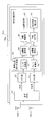
- FIG. 11 is a block diagram showing an internal configuration of a radar receiver 50a of a conventional radar apparatus.
- I signal the in-phase signal of the signal quadrature detected by the radar receiver of the radar apparatus
- Q signal the quadrature signal of the quadrature detected signal
- the AGC unit 52 amplifies the I signal output after the quadrature detection by the reception RF unit 51 with a predetermined gain.
- the AGC unit 53 amplifies the Q signal output after quadrature detection by the reception RF unit 51 with a predetermined gain.
- the I signal amplified by the AGC unit 52 is input to the A / D conversion unit 55, and the Q signal amplified by the AGC unit 53 is input to the A / D conversion unit 56.
- the I and Q signals input to the A / D conversion units 55 and 56 are signal processed by the signal processing unit 54, respectively, and the distance to the target and the arrival angle are calculated.
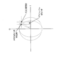
- FIG. 12 is an explanatory diagram for explaining the effect of gain variation in the AGC unit in a conventional radar apparatus.
- FIG. 12 there is a difference between the angle when the AGC units 52 and 53 operate ideally and the angle when the gains of the AGC units 52 and 53 operate with variation.
- the amplitudes of the I signal and the Q signal are different, and a phase shift amount is generated between the phase component of the I signal and the phase component of the Q signal.
- This phase shift amount becomes an error that cannot be ignored when the arrival angle estimation unit 63 of the signal processing unit 54 estimates the arrival angle of the target. Therefore, when this phase shift amount occurs, it is difficult to estimate the arrival angle of the target with high accuracy.
- the present invention has been made in view of the above-described conventional circumstances, and corrects a phase shift amount generated between the I signal and the Q signal after quadrature detection of the reflected wave signal reflected by the target in real time and appropriately.
- An object of the present invention is to provide a radar apparatus that suppresses deterioration in estimation accuracy of a target arrival angle.
- the present invention is the above-described radar apparatus, which transmits a high-frequency transmission signal from a transmission antenna at a predetermined transmission cycle, and receives a reflected wave signal reflected by a target with a reception antenna.
- a first transmission signal is generated by modulating a code obtained by concatenating the third sub code sequence and the fourth sub code sequence in the first transmission cycle, and in the second transmission cycle, the first transmission signal is generated.
- a transmission signal generation unit that generates a second transmission signal obtained by modulating a code obtained by concatenating a 5-sub code sequence and a sixth sub-code sequence, and the first and second transmission signals generated by the transmission signal generation unit Convert to transmission signal and transmit antenna And a transmission RF unit for transmitting.
- the phase shift amount generated between the I signal and the Q signal after quadrature detection of the reflected wave signal reflected by the target is corrected appropriately in real time, and the arrival angle of the target is estimated. Degradation of accuracy can be suppressed.
- segmented predetermined pulse code length 1 is a timing chart relating to the operation of the radar apparatus of the first embodiment, (a) an explanatory diagram of a transmission cycle composed of a transmission interval and a non-transmission interval, (b) an explanatory diagram of a measurement interval, and (c) a complementary code for each transmission cycle.
- Explanatory drawing explaining the relationship between the state of sequentially switching and transmitting a sequence and discrete time Timing chart regarding the operation of the AGC unit of the radar receiver, (a) an explanatory diagram for explaining how the complementary code sequence is sequentially switched for each transmission cycle, (b) an explanatory diagram of the measurement section, (c) non Explanatory drawing which showed a mode that the gain of an AGC part changes according to the elapsed time from the start timing of a transmission area.
- Explanatory drawing which shows the structure of a complex correlation value calculating part and IQ correction
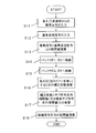
- a flowchart for explaining the operations of the complex correlation value calculation unit and the IQ correction unit The block diagram which shows the other internal structure of a transmission signal generation part, (a) The block diagram which shows the internal structure of the modification of a transmission signal generation part, (b) The block which shows the internal structure of the other modification of a transmission signal generation part Figure The block diagram which shows the internal structure of the radar receiver in the modification of 1st Embodiment Explanatory drawing explaining the nature of the conventional complementary code, (a) explanatory drawing showing the autocorrelation calculation result of one complementary code sequence, (b) explanatory drawing showing the autocorrelation calculation result of the other complementary code sequence, (c) ) Explanatory drawing showing the added value of autocorrelation calculation results of two complementary code sequences
- An explanatory view for explaining an operation of amplifying a reflected wave signal in a conventional radar apparatus (a) an explanatory view showing a transmission interval of a transmission signal and a measurement interval of a reception signal, and (b) an AGC in the measurement interval
- the radar apparatus according to the following embodiment will be described using a signal including a sub code sequence pulse-modulated using a complementary code sequence as an example of a transmission signal.
- the received signal received by the radar device includes a reflected wave signal obtained by reflecting the high-frequency transmission signal from the radar device to the target and a noise signal around the radar device.
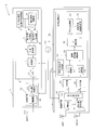
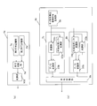
- FIG. 1 is a block diagram showing an internal configuration of the radar apparatus 1 according to the first embodiment.
- FIG. 2 is an explanatory diagram showing a procedure for generating a complementary code sequence including a sub code sequence having a sub code length obtained by dividing a predetermined pulse code length L.
- FIG. 3 is a timing chart regarding the operation of the radar apparatus 1.
- FIG. 4A is an explanatory diagram of a transmission cycle composed of a transmission interval and a non-transmission interval.
- FIG. 4B is an explanatory diagram of the measurement section.
- FIG. 6C is an explanatory diagram for explaining the relationship between the state in which complementary code sequences are sequentially switched and transmitted for each transmission period and the discrete time.
- FIG. 4 is a timing chart regarding the operation of the AGC units 19 and 20 of the radar receiver 3.
- FIG. 6A is an explanatory diagram for explaining a state in which a complementary code sequence is sequentially switched for each transmission cycle.
- FIG. 4B is an explanatory diagram of the measurement section.
- FIG. 6C is an explanatory diagram showing how the gains of the AGC units 19 and 20 change according to the elapsed time from the start timing of the non-transmission section.
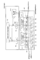
- FIG. 5 is an explanatory diagram illustrating the configuration and operation of the complex correlation value calculation unit 25 and the IQ correction unit 26.
- the radar apparatus 1 includes a local oscillator Lo, a radar transmitter 2 to which a transmission antenna ANT0 is connected, a radar receiver 3 to which a reception antenna ANT1 is connected, and a reception antenna ANT2. And a radar receiver 3a.
- the radar apparatus 1 according to the first embodiment transmits a predetermined intermittent high-frequency transmission signal generated by the radar transmitter 2 from the transmission antenna ANT0, and transmits a reflected wave signal reflected by the target to the radar receiver 3 and The signal is received by the radar receiver 3a.
- the radar apparatus 1 detects a target from the reception signals received by the radar receivers 3 and 3a.
- the target is an object to be detected by the radar apparatus 1 and is, for example, an automobile or a person, and the same applies to the following embodiments.
- the radar transmitter 2 includes a transmission signal generator 4 and a transmission RF unit 12.
- the transmission signal generation unit 4 includes a sub-code unit complementary code generation unit 5, a complex coefficient multiplication unit 6, a first code generation unit 7, a second code generation unit 8, a code switching unit 9, a modulation unit 10, , LPF (Low Pass Filter) 11.
- LPF Low Pass Filter
- the transmission signal generation unit 4 is configured to include the LPF 11, but the LPF 11 may be configured independently of the transmission signal generation unit 4.
- the transmission RF unit 12 includes a frequency conversion unit 13 and an amplifier 14.
- the transmission signal generation unit 4 Based on the reference signal generated by the local oscillator Lo, the transmission signal generation unit 4 generates a timing clock obtained by multiplying the reference signal by a predetermined multiple. Each unit of the transmission signal generation unit 4 operates based on the generated timing clock.
- the transmission signal generation unit 4 divides a complementary code sequence having a pulse code length L having L [number] elements (1) and elements ( ⁇ 1) into two, and each divided sub code sequence is divided into two.
- the baseband transmission signal r (n) is periodically generated by modulation.
- the parameter n represents a discrete time.
- the transmission signal generated by the transmission signal generation unit 4 is not a continuous signal.
- Nr [number] samples are transmitted as the baseband transmission signal r (n). Exists.
- Nu [number] samples are present as the transmission signal r (n) in the baseband.
- Tr is the transmission cycle [seconds] of the high-frequency transmission signal transmitted from the transmission antenna ANT0.
- the sub code unit complementary code generation unit 5 generates each sub code sequence (c, d) constituting the complementary code sequence (a, b) having the pulse code length L, and further, each sub code sequence (c, d) A complementary code sequence (a, b) is generated based on d).
- the code length of each sub code sequence (c, d) is represented by L / N obtained by dividing the pulse code length L of the complementary code sequence (a, b) by N.
- one complementary code sequence (a) is a concatenation of a sub code sequence (c) and a sub code sequence (d).
- the other complementary code sequence (b) is a concatenation of the sub code sequence (c) and the sub code sequence (-d).
- (a, b) each represents a complementary code sequence
- (c, d) each represents a sub-code sequence constituting the complementary code sequence.
- the parameter (p) determines the code length L of the complementary code sequence (a, b) generated by the sub code unit complementary code generation unit 5.
- the sub code unit complementary code generation unit 5 outputs the generated sub code sequence (c, d) to the complex coefficient multiplication unit 5, the first code generation unit 7, and the second code generation unit 8, respectively. .
- the complex coefficient multiplication unit 6 receives the sub code sequence (c, d) output from the sub code unit complementary code generation unit 5, and calculates the complex coefficient j for the input sub code sequence (c, d). Complex sub-code sequences (jc, jd) each multiplied are generated. The complex coefficient multiplication unit 6 outputs the generated complex sub-code sequence (jc, jd) to the first code generation unit 7 and the second code generation unit 8, respectively.
- the first code generation unit 7 outputs the sub code sequence (c, d) output from the sub code unit complementary code generation unit 5 and the complex sub code sequence (jc, jd) output from the complex coefficient multiplication unit 6. input.
- the first code generation unit 7 concatenates the sub code sequence (c) and the complex sub code sequence (jd) among the input sub code sequences and complex sub code sequences (c, d, jc, jd). As a result, a code sequence [c, jd] is generated.
- the first code generation unit 7 outputs the generated code sequence [c, jd] to the code switching unit 9.
- the code sequence generated by the first code generator 7 is referred to as “Code # 1”.
- the second code generation unit 8 uses the sub code sequence (c, d) output from the sub code unit complementary code generation unit 5 and the complex sub code sequence (jc, jd) output from the complex coefficient multiplication unit 6. input.
- the second code generation unit 8 concatenates the sub code sequence (d) and the complex sub code sequence (jc) among the input sub code sequences and complex sub code sequences (c, d, jc, jd). As a result, a code sequence [jc, d] is generated.
- the second code generation unit 8 outputs the generated code sequence [jc, d] to the code switching unit 9.
- the code sequence generated by the second code generation unit 8 is referred to as “Code # 2”.
- the code switching unit 9 receives the code sequence Code # 1 generated by the first code generation unit 7 and the code sequence Code # 2 generated by the second code generation unit 8. The code switching unit 9 sequentially switches the input code sequence Code # 1 and code sequence Code # 2 for each transmission cycle Tr and outputs the code sequence Code # 2 to the modulation unit 10 as shown in FIG. Specifically, the code switching unit 9 outputs the code sequence Code # 1 to the modulation unit 10 in the transmission period of the first transmission cycle Tr in FIG. In the transmission section of the next transmission cycle Tr, the code switching unit 9 outputs the code sequence Code # 2 to the modulation unit 10. Similarly, in the transmission section of the subsequent transmission cycle, the code switching unit 9 similarly switches the code sequence Code # 1 and the code sequence Code # 2 sequentially and outputs the same to the modulation unit 10.
- the modulation unit 10 receives the code sequence Code # 1 or the code sequence Code # 2 output from the code switching unit 9.
- the modulation unit 10 generates a transmission signal by performing pulse modulation using Nr / L samples for each code sequence on the input code sequence Code # 1 or code sequence Code # 2. Further, the modulation unit 10 generates a transmission signal by performing phase modulation as described later with reference to FIG. 6B on the input code sequence Code # 1 or code sequence Code # 2. May be. Details will be described later.
- the modulation unit 10 outputs, to the transmission RF unit 12, only the transmission signal r (n) that is equal to or less than a preset limited band among the generated transmission signals via the LPF 11.
- the transmission RF unit 12 Based on the reference signal generated by the local oscillator Lo, the transmission RF unit 12 generates a timing clock obtained by multiplying the reference signal by a predetermined multiple. The transmission RF unit 12 operates based on the generated reference signal. Specifically, the frequency conversion unit 13 receives the transmission signal r (n) generated by the transmission signal generation unit 4, performs frequency conversion on the input baseband transmission signal r (n), and performs carrier conversion. A high-frequency transmission signal in a frequency band is generated. The frequency conversion unit 13 outputs the generated high-frequency transmission signal to the amplifier 14.
- the amplifier 14 receives the output high-frequency transmission signal, amplifies the level of the input high-frequency transmission signal to a predetermined level, and outputs it to the transmission antenna ANT0.
- the amplified high-frequency transmission signal is transmitted so as to be radiated into space via the transmission antenna ANT0.
- the transmission antenna ANT0 transmits the high-frequency transmission signal output by the transmission RF unit 12 so as to be radiated into space. As shown in FIG. 3A, the high-frequency transmission signal is transmitted during the transmission interval Tw in the transmission cycle Tr, and is not transmitted during the non-transmission interval (Tr-Tw).
- the radar receiver 3 includes a reception antenna ANT1, a reception RF unit 15, an AGC unit 19, an AGC unit 20, and a signal processing unit 21.
- the radar receiving unit 3a has the same configuration as the radar receiving unit 3 except that it includes another receiving antenna ANT2 different from the receiving antenna ANT1 instead of the receiving antenna ANT1. Therefore, in the following description of the radar receivers 3 and 3a, only the radar receiver 3 will be described. However, the radar receiver 3 a performs the same operation as the radar receiver 3.
- the reception RF unit 15 includes an amplifier 16, a frequency conversion unit 17, and a quadrature detection unit 18.
- the signal processing unit 21 includes an A / D conversion unit 22, an A / D conversion unit 23, a reference transmission signal generation unit 24, a complex correlation value calculation value 25, an IQ correction unit 26, and an averaging processing unit 27.
- the arrival angle distance estimation unit 28 is provided.
- the reception antenna ANT1 receives a reflected wave signal obtained by reflecting the high-frequency transmission signal transmitted from the radar transmission unit 2 on the target and a noise signal around the radar apparatus 1 as a reception signal.
- the reflected wave signal is a high frequency band signal.
- the reception signal received by the reception antenna ANT1 is input to the reception RF unit 15.
- the radar apparatus 1 of the first embodiment is described as having two radar receivers, but the number of radar receivers is not particularly limited to two. In the radar device 1, the radar receiver holds one receiving antenna.
- the reception antenna ANT1 receives the reception signal described above in a section corresponding to the non-transmission section (Tr-Tw) in the transmission cycle Tr of the high-frequency transmission signal. Therefore, a section in which the received signal is received is a measurement section in the radar apparatus 1.
- the reception RF unit 15 generates a timing clock obtained by multiplying the reference signal by a predetermined multiple based on the reference signal generated by the local oscillator Lo.
- the reception RF unit 15 operates based on the generated timing clock.
- the amplifier 16 receives a reception signal in a high frequency band received by the reception antenna ANT1, amplifies the level of the input reception signal in the high frequency band to a predetermined level, and outputs the amplified signal to the frequency conversion unit 17. To do.
- the frequency converter 17 receives the received signal in the high frequency band output from the amplifier 16, converts the frequency of the input received signal in the high frequency band into a baseband band, and receives the frequency-converted baseband band The signal is output to the quadrature detection unit 18.
- the quadrature detection unit 18 shifts the phase components of some of the received signals of the baseband band output from the frequency conversion unit 17 by 90 degrees, thereby forming a baseband composed of the I signal and the Q signal. Generate a received signal in the band.
- the quadrature detection unit 18 outputs the generated I signal to the AGC unit 19 and outputs the generated Q signal to the AGC unit 20.
- the AGC unit 19 sets the I signal output from the quadrature detection unit 18 to the elapsed time from the start timing of the measurement section (non-transmission section) shown in FIG. Amplify with the corresponding gain.
- the gain of the AGC unit 19 is not fixed but variable as shown in FIG.
- the AGC unit 19 outputs the amplified I signal to the A / D conversion unit 22.
- the AGC unit 20 sets the Q signal output from the quadrature detection unit 18 to the elapsed time from the start timing of the measurement section (non-transmission section) shown in FIG. Amplify with the corresponding gain.
- the gain of the AGC unit 20 is not fixed but variable as shown in FIG.
- the AGC unit 20 outputs the amplified Q signal to the A / D conversion unit 23.
- the A / D conversion unit 22 converts the I signal into digital data by performing sampling at the discrete time k on the baseband I signal output from the AGC unit 19.
- the A / D conversion unit 23 converts the Q signal into digital data by performing sampling at the discrete time k on the Q signal in the baseband band output from the AGC unit 20.
- the parameter k represents a discrete time corresponding to the number of samples of the baseband transmission signal r (n) included in the high-frequency transmission signal.
- the reception signal at the discrete time k of the reception antenna ANT1 is expressed by Equation (4) using the in-phase signal I (s, k) of the reception signal and the quadrature signal Q (s, k) of the reception signal.
- the gain of the AGC unit 19 or the AGC unit 20 at the discrete time k is expressed as g (k, I) or g (k, Q).
- the discrete time k 2 (Nr + Nu) indicates the end timing of the transmission cycle Tr of the code sequence Code # 2. That is, the radar receiver 3 has a transmission cycle (2Tr) that is twice the transmission cycle Tr of the high-frequency transmission signal of the code sequence Code # 1 and the transmission cycle Tr of the high-frequency transmission signal of the code sequence Code # 2.
- the signal processing section 21 periodically calculates the signal processing section.
- K Nr at the end timing.
- the range from the transmission start timing of the high-frequency transmission signal of the code sequence Code # 1 to the transmission end timing of the high-frequency transmission signal of the code sequence Code # 2 is set repeatedly for the discrete time k.
- the reference transmission signal generator 24 multiplies the reference signal by a predetermined multiple based on the reference signal generated by the local oscillator Lo in the same manner as the transmission signal generator 4 in synchronization with the operation of the transmission signal generator 4. Generated timing clock.
- the reference transmission signal generation unit 24 periodically generates a reference transmission signal r (n) having the same baseband as the transmission signal generated by the transmission signal generation unit 4 based on the generated reference signal.
- the reference transmission signal generation unit 24 outputs the generated reference transmission signal r (n) to the complex correlation value calculation unit 25.
- the transmission signal generated by the transmission signal generation unit 4 of the radar transmission unit 2 and the reference transmission signal generated by the reference transmission signal generation unit 24 are based on an I signal Ir (k) and a Q signal Qr (k).
- the band-band signal r (n) can be expressed as Equation (5).
- the parameter g r (k) represents the gain of the AGC units 19 and 20 at the discrete time k.
- the complex correlation value calculation unit 25 includes a plurality of shift registers R1 to R8, a first sub-code unit correlation value calculation unit FR, a second sub-code unit correlation value calculation unit SR, Buffers B1 and B2.
- the IQ correction unit 26 includes buffers B3 and B4, a correction coefficient calculation unit ACC, corrected correlation value calculation units M1 and M2, and a complementary code sequence correlation value calculation unit CC.
- each of the shift registers R1 to R8 inputs the complex signal x (s, k) converted by the A / D converters 22 and 23 (S11).
- Each shift register R1 to R8 inputs the complex signal x (s, k) in response to shifting the parameter m in equations (6) and (7) described later.
- the parameter m represents the shift time in the calculation of the correlation value.
- the first sub-code unit correlation value calculation unit FR and the second sub-code unit correlation value calculation unit SR each receive the reference transmission signal r (n) output by the reference transmission signal generation unit 24 (S12).
- the first sub-code unit correlation value calculation unit FR calculates the complex conjugate value of the complex signal x (s, k) input in step S11 and the reference transmission signal r (n) input in step S12. Is calculated as shown in Equation (6) (S13).
- the second sub-code unit correlation value calculation unit SR also correlates the complex value of the complex signal x (s, k) input in step S11 and the complex conjugate value of the reference transmission signal r (n) input in step S12. Is calculated as shown in Equation (7) (S13).
- the first sub-code unit correlation value calculation unit FR and the second sub-code unit correlation value calculation unit SR each perform the reference output from the reference transmission signal generation unit 24 in step S12 according to the range of the discrete time k.
- the transmission signal r (n) is switched and input.
- the reference transmission signal is input (S12).
- the reference transmission signal is input (S12).
- An asterisk (*) represents a complex conjugate operator.
- a sub code sequence correlation value between the complex signal x (s, k) and the sub code sequence of the reference transmission signal r (n) input in step S12 is calculated (S13).
- the second sub-code unit correlation value calculating unit SR receives the complex signal x (s, k) input in step S11 and the step S12 for the complex sub-code sequence having the sub code length L / N.
- a complex sub-code sequence correlation value with the complex sub-code sequence of the reference transmission signal r (n) is calculated (S13).
- a sub code sequence correlation value with the sub code sequence (c) of the transmission signal r (n) is calculated according to the equation (8) (S13).
- a complex sub-code sequence correlation value with the complex sub-code sequence (jd) of the signal r (n) is calculated according to Equation (9) (S13).
- the first sub-code unit correlation value calculation unit FR temporarily stores each sub-code sequence correlation value calculated in step S13 in the buffer B1 in the complex correlation value calculation unit 25 (S14), and the IQ correction unit 26 is output to the buffer B3 (S15). Further, the second sub-code unit correlation value calculator SR temporarily stores each complex sub-code sequence correlation value calculated in step S13 in the buffer B2 in the complex correlation value calculator 25 (S14). The data is output to the buffer B4 of the IQ correction unit 26 (S15).
- a complex sub-code sequence correlation value with the complex sub-code sequence (jc) of the transmission signal r (n) is calculated according to Equation (10) (S13).
- a sub code sequence correlation value with the sub code sequence (d) of the reference transmission signal r (n) is calculated according to the equation (11) (S13).
- the first sub-code unit correlation value calculation unit FR temporarily stores each complex sub-code sequence correlation value calculated in step S13 in the buffer B1 in the complex correlation value calculation unit 25 (S14), and performs IQ correction.
- the data is output to the buffer B3 of the unit 26 (S15).
- the second sub-code unit correlation value calculation unit SR temporarily stores each sub-code sequence correlation value calculated in step S13 in the buffer B2 in the complex correlation value calculation unit 25 (S14), and IQ
- the data is output to the buffer B4 of the correction unit 26 (S15).
- the first correction coefficient H 1 (s, k) is a complex sub code sequence correlation value AC 1 _sub 2 (s, k + (Nr / N)) when a complex sub code sequence is used for the transmission signal.
- the sub-code sequence correlation value AC 1 _sub 1 (s, k) in the case where the sub-code sequence is used for the transmission signal are calculated as coefficients when equalizing each amplitude level (amplitude scale).
- the calculated first correction coefficient H 1 (s, k) is multiplied by AC 1 _sub 2 (s, k + (Nr / N)) or AC 1 _sub 1 (s, k).
- the calculated first correction coefficient H 1 (s, k) is multiplied, and addition processing is performed as shown in Equation (13).
- the mathematical expression (12) represents the sub code sequence correlation value when the sub code sequence (c) is used for the transmission signal and the complex sub code sequence (jd) for the transmission signal. ) Indicates that the gains of the AGC units 19 and 20 are equal when the amplitude levels are the same as the complex sub-code sequence correlation value. That is, when Equation (12) is established, the gains of the AGC units 19 and 20 do not vary.
- a correction coefficient H 1 (s, k) for appropriately correcting the phase shift amount with respect to the Q signal can be calculated.
- the complex sub-code sequence correlation value AC 1 _sub 2 (s, k + (Nr / N)) is multiplied by the correction coefficient H 1 (s, k).
- the complementary code sequence correlation value calculation unit CC adds the corrected correlation value calculation result multiplied in step S17 and the sub code sequence correlation value calculated according to Equation (8) according to Equation (13) ( S18).
- the correlation value calculated according to Equation (13) represents the correlation value of the complementary code sequence of code sequence Code # 1.
- the range of the discrete time k may be further limited on the premise that the existence range of the target to be measured by the radar apparatus 1 is at a short distance from the radar apparatus 1.
- the radar apparatus 1 can reduce the calculation amount by the complex correlation value calculation unit 25 and the IQ correction unit 26. That is, the radar apparatus 1 can reduce the amount of power consumed by the signal processing unit 21.
- the second correction coefficient H 2 (s, k) is transmitted with the sub code sequence correlation value AC 2 _sub 2 (s, k + (Nr / N)) when the sub code sequence is used for the transmission signal. This is calculated as a coefficient for equalizing each amplitude level (amplitude scale) with the complex sub code sequence correlation value AC 2 _sub 1 (s, k) when a complex sub code sequence is used for the signal.
- the calculated second correction coefficient H 2 (s, k) is multiplied by AC 2 _sub 2 (s, k + (Nr / N)) or AC 2 _sub 1 (s, k).
- the mathematical formula (14) represents the complex sub code sequence correlation value when the complex sub code sequence (jc) is used for the transmission signal and the sub signal for the transmission signal.
- the amplitude levels are the same as the sub code sequence correlation value when the code sequence (d) is used, it indicates that the gains of the AGC units 19 and 20 are equal. That is, when the formula (14) is established, the gains of the AGC units 19 and 20 do not vary.
- a correction coefficient H 2 (s, k) for correct correction can be calculated.
- the sub-code sequence correlation value AC 2 —sub 2 (s, k + (Nr / N)) is multiplied by the correction coefficient H 2 (s, k).
- the complementary code sequence correlation value calculation unit CC adds the corrected correlation value calculation result multiplied in step S17 and the complex sub code sequence correlation value calculated according to equation (10) according to equation (15). (S18).
- the correlation value calculated according to Equation (15) represents the correlation value of the complementary code sequence of code sequence Code # 2.
- the range of the discrete time k may be further limited on the premise that the existence range of the target to be measured by the radar apparatus 1 is at a short distance from the radar apparatus 1.
- the radar apparatus 1 can reduce the calculation amount by the complex correlation value calculation unit 25 and the IQ correction unit 26. That is, the radar apparatus 1 can reduce the amount of power consumed by the signal processing unit 21.
- the averaging processing unit 27 calculates the correlation value of the complementary code sequence of the code sequence Code # 1 calculated according to the equation (13) and the correlation value of the complementary code sequence of the code sequence Code # 2 calculated according to the equation (15). Is added.
- the discrete time k in the calculation of the correlation value of the complementary code sequence of the code sequence Code # 2 is one period of the transmission cycle Tr compared to the discrete time k in the calculation of the correlation value of the complementary code sequence of the code sequence Code # 1. It's a minute late.
- the averaging processing unit 27 transmits the discrete time k in the calculation of the correlation value of the complementary code sequence of the code sequence Code # 2 in consideration of the difference in the discrete time k in the calculation of the correlation value of the complementary code sequence of each code sequence.
- An operation such as Expression (16) shifted in time by the period Tr is performed.
- the correlation value represented by Equation (16) is the correlation between the complementary code sequence (code sequence Code # 1, code sequence Code # 2) generated by the transmission signal generation unit 4 and the received signal received by the receiving antenna ANTs. Value.
- the radar apparatus 1 can obtain a signal in which the range side lobe is suppressed to a low level as shown in the above-described Expression (1) and FIG. 8 according to the calculation of Expression (16) by the averaging processing unit 27. .
- the arrival angle distance estimation unit 28 calculates the correlation value AC 1 (s, k) + AC 2 (s, k + Nr + Nu) of the complementary code sequences (code sequence Code # 1, code sequence Code # 2) calculated by the averaging processing unit 27.
- the target angle of arrival and the distance to the target are estimated.
- the arrival angle estimation calculation by the arrival angle distance estimation unit 25 is a known technique and can be realized by referring to, for example, the following Reference Non-Patent Document 1. Further, the estimation calculation of the distance to the target by the arrival angle distance estimation unit 28 can be realized by referring to the following non-patent document 2.
- the arrival angle distance estimation unit 28 calculates the level of the received signal at the receiving antenna based on the added correlation value of the complementary code sequence at the receiving antenna ANT1 with respect to the target arrival angle.
- the level of the received signal includes a phase component of the target arrival angle.
- the arrival angle distance estimation unit 28 estimates the angle of the phase component when the level of the reception signal takes the maximum value as the arrival angle of the target.
- the arrival angle distance estimation unit 28 based on the correlation value obtained by adding the complementary code sequence in the reception antenna ANT1 with respect to the distance to the target, the discrete time and the high frequency transmission when the correlation value takes the maximum value. Based on the time difference with the signal transmission time, the target distance is estimated.
- the amount of phase shift generated between the I signal and the Q signal after quadrature detection of the reflected wave signal reflected by the target is appropriately corrected, and the target It is possible to suppress the deterioration of the estimation accuracy of the arrival angle of.
- the radar apparatus 1 performs pulse compression on the high-frequency transmission signal with a code length L / N, a correlation value with an improved SNR (Signal Noise Ratio) in the reflected wave signal reflected by the target is obtained. Obtainable. For this reason, the radar apparatus 1 can calculate the correction coefficient for appropriately correcting the phase shift amount between the I signal and the Q signal with high accuracy, and can suppress the estimated deterioration of the arrival angle of the target. .
- low range side lobe characteristics can be maintained by using complementary code sequences (code sequence Code # 1, code sequence Code # 2). Thereby, the estimated deterioration of the arrival angle and distance of the target by the radar apparatus 1 can be suppressed.
- the radar apparatus 1 it is possible to calculate a correction coefficient corresponding to a variation in gains of the AGC units 19 and 20 that are affected by an external environment such as temperature in real time for a predetermined measurement period. it can.
- the representation of the complementary code sequence (a, b) is not limited to this representation.
- each coefficient (A, B, C, D) (1, j, j, 1) is established in the first embodiment.
- the following coefficients are used as the coefficients, the same effects as those of the first embodiment can be obtained.
- each coefficient (A, B, C, D) (j, -1, -1, j).
- each coefficient (A, B, C, D) ( ⁇ 1, ⁇ j, ⁇ j, ⁇ 1).
- ⁇ j is an inverted complex sequence.
- each coefficient (A, B, C, D) (j, 1, 1, j).
- each coefficient (A, B, C, D) ( ⁇ j, ⁇ 1, ⁇ 1, ⁇ j).
- each coefficient (A, B, C, D) ( ⁇ 1, j, j, ⁇ 1).
- the configuration of the radar apparatus 1 has a problem that a phase shift amount is generated between the I signal and the Q signal due to a variation between the gains of the AGC units 19 and 20 of the radar receiver 3.
- the problem was solved.
- the radar receiver 3 has the AGC units 19 and 20, but also when the radar receiver 3 is a direct conversion type radar apparatus that does not have the AGC units 19 and 20, after quadrature detection.
- a phase shift amount occurs between the I signal and the Q signal. That is, even in the case of the direct conversion type radar apparatus, a phase shift amount occurs between the I signal and the Q signal after the quadrature detection due to a hardware error factor of the quadrature detection unit of the reception RF unit.
- the second modification of the first embodiment includes a configuration of a direct conversion type radar apparatus that does not include the AGC units 19 and 20 in the radar receiver 3 of the first embodiment. That is, the radar apparatus according to the second modification of the first embodiment includes a radar transmission unit similar to the radar transmission unit 2 of the radar apparatus 1, omits the AGC units 19 and 20 from the radar reception unit 3 of the radar apparatus 1, Other configurations have the same configuration.
- the hardware of the quadrature detection unit of the reception RF unit A phase shift amount generated between the I signal and the Q signal generated according to the error factor can be corrected appropriately.
- the radar transmission unit of the radar apparatus generates the transmission signal shown in FIG. 7A instead of the transmission signal generation unit 4 of the radar apparatus 1 of the first embodiment.
- the configuration of the unit 4a or the transmission signal generation unit 4b shown in FIG. Note that the radar receiver in the radar device of Modification 3 of the first embodiment is the same as the radar device 1 of the first embodiment. For this reason, the description of the radar receiver in the radar apparatus according to Modification 3 of the first embodiment is omitted.
- FIG. 7 is a block diagram showing another internal configuration of the transmission signal generation unit.
- FIG. 4A is a block diagram showing an internal configuration of a transmission signal generation unit 4a that is a modification of the transmission signal generation unit 4.
- FIG. 6B is a block diagram showing an internal configuration of a transmission signal generation unit 4b which is another modification of the transmission signal generation unit 4.
- the transmission signal generation unit 4a includes a first code storage unit 7a, a second code storage unit 8a, a code switching unit 9a, and a modulation unit 10a.
- the first code storage unit 7a stores in advance the sub code sequence generated by the first code generation unit 7 in the radar apparatus 1 of the first embodiment.
- the second code storage unit 8a stores in advance the sub code sequence generated by the second code generation unit 8 in the radar apparatus 1 of the first embodiment.
- the code switching unit 9a Based on the reference signal generated by the local oscillator Lo, the code switching unit 9a generates a timing clock obtained by multiplying the reference signal by a predetermined multiple.
- the code switching unit 9a reads the stored sub code sequence from the first code storage unit 7a or the second code storage unit 8a based on the generated timing clock.
- the operation after the code switching unit 9a reads and the operation of the modulation unit 10a are the same as the operation of the code switching unit 9 and the operation of the modulation unit 10 in the transmission signal generation unit 4 of the first embodiment. Description of the contents of is omitted.
- the transmission signal generation unit 4b includes a sub-code unit complementary code generation unit 5b, a first code generation unit 7b, a second code generation unit 8b, and a code switching unit 9b.
- the first code generation unit 7b includes a modulation unit 31b, a 90-degree phase shift modulation unit 32b, and a P / S modulation unit 33b.
- the second code generation unit 8b includes a 90-degree phase shift modulation unit 34b, a modulation unit 35b, and a P / S conversion unit 36b.
- the sub code unit complementary code generation unit 5b generates a sub code sequence (c) in the same manner as the sub code unit complementary code generation unit 5 of the first embodiment, and the generated sub code sequence (c). For example, it outputs to the modulation part 31b which modulates with an I axis (in-phase axis). Further, the sub code unit complementary code generation unit 5b generates a sub code sequence (d) in the same manner as the sub code unit complementary code generation unit 5 of the first embodiment, and generates the generated sub code sequence (d). On the other hand, for example, it outputs to the 90 degree phase shift modulation part 32b which modulates with Q axis (orthogonal axis).
- the sub code unit complementary code generation unit 5b generates a sub code sequence (c) in the same manner as the sub code unit complementary code generation unit 5 of the first embodiment, and the generated sub code sequence (c). For example, the signal is output to the 90-degree phase shift modulator 34b that performs modulation on the Q axis (in-phase axis). Further, the sub code unit complementary code generation unit 5b generates a sub code sequence (d) in the same manner as the sub code unit complementary code generation unit 5 of the first embodiment, and generates the generated sub code sequence (d). On the other hand, it outputs to the modulation
- the modulation unit 31b receives the sub code sequence (c) generated by the sub code unit complementary code generation unit 5b, modulates the sub code sequence (c) with the I axis (in-phase axis), and generates the modulated signal. Is output to the P / S converter 33b.
- the 90-degree phase shift modulation unit 32b receives the sub code sequence (d) generated by the sub code unit complementary code generation unit 5b, modulates the sub code sequence (d) with the Q axis (orthogonal axis), and The modulated signal is output to the P / S converter 33b. Note that the 90-degree phase shift modulation unit 32b modulates the sub code sequence (d) on the Q axis by multiplying the complex coefficient j by the complex coefficient multiplication unit 6 of the transmission signal generation unit 4 of the first embodiment. It corresponds to being done.
- the P / S converter 33b receives the signal output from the modulator 31b and the signal output from the 90-degree phase shift modulator 32b.
- the P / S modulation unit 33b outputs the signal output from the modulation unit 31b to the code switching unit 9b, and then outputs the signal output from the 90-degree phase shift modulation unit 32b to the code switching unit 9b.
- This operation is the same as the operation of outputting the code sequence [c, jd] to the code switching unit 9 in the first code generation unit 7 of the first embodiment.
- the 90-degree phase shift modulation unit 34b receives the sub code sequence (c) generated by the sub code unit complementary code generation unit 5b, modulates the sub code sequence (c) with the Q axis (orthogonal axis), and The modulated signal is output to the P / S converter 36b. Note that the 90-degree phase shift modulation unit 34b modulates the sub code sequence (c) with the Q axis by multiplying the complex coefficient j by the complex coefficient multiplication unit 6 of the transmission signal generation unit 4 of the first embodiment. It corresponds to being done.
- the modulation unit 35b receives the sub code sequence (d) generated by the sub code unit complementary code generation unit 5b, modulates the sub code sequence (d) with the I axis (in-phase axis), and generates the modulated signal. Is output to the P / S converter 36b.
- the P / S converter 36b receives the signal output from the 90-degree phase shift modulator 34b and the signal output from the modulator 35b.
- the P / S modulation unit 36b outputs the signal output from the 90-degree phase shift modulation unit 34b to the code switching unit 9b, and then outputs the signal output from the modulation unit 35b to the code switching unit 9b.
- This operation is the same as the operation of outputting the code sequence [jc, d] to the code switching unit 9 in the first code generation unit 7 of the first embodiment.
- the code switching unit 9b includes a signal output from the first code generation unit 7b, that is, a modulated code sequence Code # 1, and a signal output from the second code generation unit 8b, that is, a modulated code sequence Code. As shown in FIG. 3C, # 2 is sequentially switched every transmission cycle Tr and output to the modulation unit 10.
- the radar apparatus of the third modification of the first embodiment it is possible to have an alternative configuration of the transmission signal generation unit 4 of the first embodiment.
- the configuration of the transmission signal generation unit 4b can be simplified.
- the IQ correction unit 26 of the signal processing unit 21 appropriately corrects the amount of phase shift between the I signal and the Q signal caused by the gain variation between the AGC units 19 and 20. It has been explained that the degradation of the estimation accuracy of the target arrival angle is suppressed.
- the amount of phase rotation accompanying the movement of the target is measured based on the correlation value shown in the mathematical expression (16) added by the averaging processing unit 27 of the first embodiment. Then, the Doppler frequency is estimated.
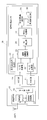
- FIG. 8 is a block diagram showing an internal configuration of the radar receiver 3b according to Modification 4 of the first embodiment.
- the radar receiver 3b includes a reception antenna ANT1, a reception RF unit 15, an AGC unit 19, an AGC unit 20, and a signal processing unit 21b.
- the signal processing unit 21b includes an A / D conversion unit 22, an A / D conversion unit 23, a reference transmission signal generation unit 24, a complex correlation value calculation unit 25, an IQ correction unit 26, and an averaging processing unit 27.
- the phase rotation amount measuring unit 29 and the Doppler frequency estimating unit 30 are provided.
- the phase rotation amount measurement unit 29 uses the correlation value of the complementary code sequence calculated by the averaging processing unit 27 as a reference correlation value, and is based on the correlation value of the complementary code sequence in each transmission period over a plurality of transmission periods NTx. Then, the phase rotation amount ⁇ (k) is measured. The phase rotation amount measurement unit 29 outputs the measured phase rotation amount ⁇ (k) to the Doppler frequency estimation unit 30.
- the Doppler frequency estimation unit 30 calculates the phase rotation amount accompanying the movement of the target, that is, the Doppler frequency f d (k), using Equation (17).
- the parameter NTx is the observation time [seconds] of the correlation value of the complementary code sequence added by the averaging processing unit 27.
- the radar apparatus of the modification 4 of 1st Embodiment based on the correlation value of the complementary code sequence calculated by the averaging process part 27, the amount of phase rotation and Doppler frequency accompanying a movement of a target are obtained. Estimation can be performed with high accuracy.
- the averaging processing unit 27 obtains a low-range sidelobe characteristic with the addition result of the correlation values in the transmission period twice the transmission period Tr of the high-frequency transmission signal as one unit. I explained that I can do it. However, the averaging processing unit 27 further calculates the addition result of the correlation values in the double transmission cycle over a plurality of transmission cycles, and calculates the addition result of the correlation values in the calculated double transmission cycle. It may be averaged. Thereby, the radar apparatus can obtain a reception signal in which the noise signal is further suppressed. That is, the calculation for estimating the arrival angle of the target and estimating the distance can be performed with high accuracy.
- the A / D converters 22 and 23 perform oversampling according to the discrete time k on the baseband I signal and Q signal amplified by the AGC units 19 and 20. Convert to digital data.
- the radar receivers 3 and 3a do not need to perform A / D conversion at the same sampling rate as the baseband transmission signal in the radar transmitter 2.
- a baseband transmission signal is generated using the number of samples of Nr with respect to the code length L. This corresponds to oversampling of Nr / L samples per code.
- the radar receivers 3 and 3a can process the received signal as long as the number of samples is one or more times per code.
- the radar apparatus appropriately corrects the phase shift amount generated between the I signal and the Q signal after quadrature detection of the signal reflected by the target, and suppresses the deterioration of the estimation accuracy of the target arrival angle. It is useful as a radar device.
Abstract
The amount of a phase shift, which occurs between an I-signal and a Q-signal after the quadrature detection of a signal reflected by a target, can be corrected in real time and appropriately, thereby suppressing the degradation of precision of estimating the arrival angle of the target. A high frequency transport signal is transmitted via a transmission antenna in a given transmission period, and a signal of a reflected wave, which is reflected by the target, is received via a reception antenna. First and second sub-code sequences each have a sub-code length obtained by dividing a code sequence having a given code length. Third, fourth, fifth and sixth sub-code sequences are obtained by multiplying each of the first and second sub-code sequences by two different factors. A first transport signal, which is obtained by modulating the codes obtained by coupling the third and fourth sub-code sequences, is generated in a first transmission period. A second transport signal, which is obtained by modulating the codes obtained by coupling the fourth and fifth sub-code sequences, is generated in a second transmission period. The generated first and second transport signals are converted to high frequency transport signals, which are transmitted via the transmission antenna.
Description
本発明は、ターゲットに反射された反射波の信号をアンテナで受信して当該ターゲットを検出するレーダ装置に関する。
The present invention relates to a radar apparatus that receives a reflected wave signal reflected from a target by an antenna and detects the target.
レーダ装置は、測定地点から電波を空間に放射し、ターゲットにより反射された反射波を受信することにより、当該測定地点とターゲットとの距離、方向等を測定する装置である。特に近年、マイクロ波又はミリ波等の波長の短い電波を用いた高分解能な測定により、自動車だけではなく歩行者等をターゲットとして検出可能なレーダ装置の開発が進められている。
A radar device is a device that measures the distance, direction, and the like between a measurement point and a target by radiating radio waves from the measurement point into space and receiving a reflected wave reflected by the target. In particular, in recent years, a radar apparatus capable of detecting not only an automobile but also a pedestrian or the like by high-resolution measurement using a short-wave radio wave such as a microwave or a millimeter wave has been developed.
レーダ装置は、近距離にいるターゲットと遠距離にいるターゲットとからの反射波が混合された受信信号を受信する。特に、近距離にいるターゲットからの反射波の信号の自己相関特性によりレンジサイドローブが生じる場合、レーダ装置の受信の際に、このレンジサイドローブと、遠距離にいるターゲットからの反射波の信号とが混在し、従って、レーダ装置における遠距離にいるターゲットの検出精度が劣化することがある。
The radar device receives a reception signal in which reflected waves from a target at a short distance and a target at a long distance are mixed. In particular, when a range side lobe occurs due to the autocorrelation characteristics of a reflected wave signal from a target at a short distance, this range side lobe and the reflected wave signal from a target at a long distance are received when the radar device receives the signal. Therefore, the detection accuracy of a target at a long distance in the radar apparatus may be deteriorated.
また、レーダ装置は、測定地点から同じ距離に自動車と歩行者とがいる場合には、レーダ反射断面積(RCS: Radar cross section)の異なる自動車と歩行者とからの反射波がそれぞれ混合された受信信号を受信することがある。歩行者(人)のレーダ反射断面積は自動車のレーダ反射断面積に比べると低いと言われている。このため、レーダ装置は、たとえ測定地点から同じに距離に自動車と歩行者とがいる場合でも、自動車だけではなく歩行者からの反射波も適正に受信する必要がある。
In addition, when the car and the pedestrian are at the same distance from the measurement point, the radar device mixed the reflected waves from the car and the pedestrian with different radar reflection cross sections (RCS: Radar cross section). Received signals may be received. It is said that the radar reflection cross section of a pedestrian (person) is lower than the radar reflection cross section of an automobile. For this reason, the radar apparatus needs to properly receive not only the automobile but also the reflected wave from the pedestrian even when the automobile and the pedestrian are at the same distance from the measurement point.
従って、上述した様な高分解能な測定が要求されるレーダ装置には、送信の際に低レンジサイドローブレベルとなる特性(以下、低レンジサイドローブ特性)を有するパルス波又はパルス変調波が送信されることが要求される。更に、当該レーダ装置における受信の際には、当該受信した信号に対して広い受信ダイナミックレンジを有することが要求される。
Therefore, a pulse wave or a pulse-modulated wave having a characteristic (hereinafter referred to as a low-range sidelobe characteristic) that transmits a low-range sidelobe level during transmission is transmitted to a radar apparatus that requires high-resolution measurement as described above. It is required to be done. Furthermore, at the time of reception in the radar device, it is required that the received signal has a wide reception dynamic range.
上述した低レンジサイドローブ特性に関して、従来から、低レンジサイドローブ特性を有するパルス波又はパルス変調波として、相補符号を用いて送信するパルス圧縮レーダが知られている。ここで、パルス圧縮とは、パルス信号をパルス変調又は位相変調してパルス幅の広い信号を用いて送信し、受信後の信号処理において当該受信された信号を復調してパルス幅の狭い信号に変換する方法である。パルス圧縮によれば、ターゲットの探知距離を増大することができ、更に、当該探知距離に対する距離推定精度を向上することができる。
Regarding the low-range sidelobe characteristics described above, conventionally, pulse compression radars that transmit using complementary codes as pulse waves or pulse-modulated waves having low-range sidelobe characteristics are known. Here, the pulse compression means that a pulse signal is subjected to pulse modulation or phase modulation and transmitted using a signal having a wide pulse width, and the received signal is demodulated in a signal processing after reception to obtain a signal having a narrow pulse width. How to convert. According to the pulse compression, the detection distance of the target can be increased, and further, the distance estimation accuracy with respect to the detection distance can be improved.
また、相補符号は、複数、例えば2つの相補符号系列(an、bn)からなり、一方の相補符号系列の自己相関演算結果と他方の相補符号系列の自己相関演算結果とにおいて、遅延時間(シフト時間)τを一致させて各自己相関演算結果を加算した場合に、レンジサイドローブがゼロとなる性質を有する。なお、パラメータnはn=1、2、・・・、Lであり、パラメータLは符号系列長を示す。
The complementary code is composed of a plurality of, for example, two complementary code sequences (a n , b n ), and the delay time between the autocorrelation calculation result of one complementary code sequence and the autocorrelation calculation result of the other complementary code sequence (Shift time) When the autocorrelation calculation results are added while matching τ, the range side lobe is zero. The parameter n is n = 1, 2,..., L, and the parameter L indicates the code sequence length.
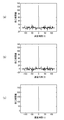
この様な相補符号の性質に関して、図9を参照して説明する。図9は、従来の相補符号の性質を説明する説明図である。同図(a)は、一方の相補符号系列anの自己相関演算結果を示す説明図である。同図(b)は、他方の相補符号系列bnの自己相関演算結果を示す説明図である。同図(c)は、2つの相補符号系列(an、bn)の自己相関演算結果の加算値を示す説明図である。
The nature of such complementary codes will be described with reference to FIG. FIG. 9 is an explanatory diagram for explaining the nature of a conventional complementary code. FIG (a) is an explanatory diagram showing an autocorrelation calculation result of one of the complementary code sequence a n. FIG (b) is an explanatory diagram showing the result of the autocorrelation calculation of the other complementary code sequence b n. FIG. 6C is an explanatory diagram showing the added value of the autocorrelation calculation results of two complementary code sequences (a n , b n ).
2つの相補符号系列(an、bn)のうち一方の相補符号系列anの自己相関演算結果は、数式(1)に従って導出される。他方の相補符号系列bnの自己相関演算結果は、数式(2)に従って導出される。なお、パラメータRは自己相関演算結果を示す。但し、n>L又はn<1の場合には、2つの相補符号系列(an、bn)は共にゼロとする。なお、アスタリスク*は複素共役演算子を示す。
Two complementary code sequences (a n, b n) one of the complementary code sequences a n autocorrelation calculation result of the is derived according to equation (1). Autocorrelation calculation result of the other complementary code sequence b n is derived according to equation (2). The parameter R indicates the autocorrelation calculation result. However, when n> L or n <1, the two complementary code sequences (a n , b n ) are both zero. The asterisk * indicates a complex conjugate operator.


数式(1)に従って導出された一方の相補符号系列anの自己相関演算結果Raa(τ)は、図9(a)に示す様に、遅延時間τがゼロのときにピークが立ち、遅延時間(シフト時間)τがゼロでない場合にはレンジサイドローブが存在する。同様に、数式(2)に従って導出された他方の相補符号系列bnの自己相関演算結果Rbb(τ)は、図9(b)に示す様に、遅延時間τがゼロのときにピークが立ち、遅延時間τがゼロでない場合にはレンジサイドローブが存在する。
Equation (1) one of the complementary code sequences a n autocorrelation calculation result derived according to R aa (tau) is as shown in FIG. 9 (a), standing the peak when the delay time tau is zero, the delay If the time (shift time) τ is not zero, there is a range side lobe. Similarly, the autocorrelation calculation result R bb (τ) of the other complementary code sequence b n derived according to Equation (2) has a peak when the delay time τ is zero, as shown in FIG. 9B. When the delay time τ is not zero, a range side lobe exists.
これらの自己相関演算結果(Raa(τ)、Rbb(τ))の加算値は、図9(c)に示す様に、遅延時間τがゼロのときにピークが立ち、遅延時間τがゼロでない場合にはレンジサイドローブが存在せずにゼロになる。これを数式(3)にて示す。なお、図9(a)~(c)の横軸は自己相関演算における遅延時間(τ)を示し、縦軸は演算された自己相関演算結果を示す。
The sum of these autocorrelation calculation results (R aa (τ), R bb (τ)) has a peak when the delay time τ is zero, as shown in FIG. If it is not zero, there will be no range side lobe and it will be zero. This is shown by Equation (3). 9A to 9C, the horizontal axis indicates the delay time (τ) in the autocorrelation calculation, and the vertical axis indicates the calculated autocorrelation calculation result.

また、上述した様なパルス圧縮を用いた従来のパルス圧縮レーダとして、特許文献1に示すパルス圧縮送受信装置及びパルス圧縮送受信方法が知られている。
Also, as a conventional pulse compression radar using pulse compression as described above, a pulse compression transmission / reception apparatus and a pulse compression transmission / reception method disclosed in Patent Document 1 are known.
特許文献1では、送信装置は、相補系列の一方でパルス内位相変調した幅Tのパルスと、この送信パルス幅T以上の時間間隔wをあけ、相補系列の他方でパルス内位相変調した幅Tのパルスを送信する。更に、送信装置は、これら2連の送信パルスの反射パルス受信後に、PRI(パルス繰り返し間隔)ごとに2連の送信パルスを送信する。受信装置の相関器は、時間間隔(2T+w)の受信信号の最初の時間間隔Tの信号と、最初の送信パルスの変調に用いた相補系列で変調した参照信号との相関を求める。
In Patent Document 1, the transmitting apparatus has a pulse having a width T that has undergone intra-pulse phase modulation in one of the complementary sequences and a width T that has undergone intra-pulse phase modulation in the other of the complementary sequences with a time interval w that is equal to or greater than the transmission pulse width T. Send a pulse. Further, after receiving the reflected pulse of these two transmission pulses, the transmission device transmits two transmission pulses for each PRI (pulse repetition interval). The correlator of the receiving apparatus obtains a correlation between the signal at the first time interval T of the received signal at the time interval (2T + w) and the reference signal modulated by the complementary sequence used for the modulation of the first transmission pulse.
更に、受信装置の相関器は、最後の時間間隔Tの信号と、相補系列の他方の系列で変調した参照信号との相関を求める。受信信号の判断器は、相関器により求められた2つの相関結果から相関値を決定する。これにより、受信信号にドップラ周波数による位相変調がない場合のレンジサイドローブをゼロにし、ドップラ周波数による位相変調がある場合のレンジサイドローブレベルの劣化を少なくすることができる。
Further, the correlator of the receiving apparatus obtains a correlation between the signal of the last time interval T and the reference signal modulated by the other sequence of the complementary sequence. The received signal determiner determines a correlation value from the two correlation results obtained by the correlator. As a result, the range side lobe when the received signal is not phase-modulated by the Doppler frequency can be made zero, and the deterioration of the range side lobe level when the phase modulation by the Doppler frequency is present can be reduced.
また、レーダ装置による受信の際に、測定地点から近距離にいるターゲットからの到来時間の早い反射波より、遠距離にいるターゲットからの到来時間の遅い反射波の信号の減衰が大きいという性質が知られている。レーダ装置が大きな受信ダイナミックレンジを有するためには、上述した性質に関連して、ターゲットからの反射波に対してAGC(Auto Gain Control)部で当該反射波の信号を増幅することが知られている。これに関して図10を参照して説明する。
In addition, when receiving by a radar device, the reflected wave signal having a late arrival time from a target at a long distance is more attenuated than the reflected wave having a short arrival time from a target at a short distance from the measurement point. Are known. In order for the radar apparatus to have a large reception dynamic range, it is known that an AGC (Auto-Gain-Control) unit amplifies the signal of the reflected wave with respect to the reflected wave from the target in relation to the above-described properties. Yes. This will be described with reference to FIG.
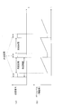
図10は、従来のレーダ装置において反射波の信号を増幅する動作を説明する説明図である。同図(a)は、送信信号の送信区間と受信信号の測定区間とを示す説明図である。同図(b)は、受信信号の測定区間内にAGC部で増幅するゲインの変化を示す説明図である。
FIG. 10 is an explanatory diagram for explaining an operation of amplifying a reflected wave signal in a conventional radar apparatus. FIG. 4A is an explanatory diagram showing a transmission interval of a transmission signal and a measurement interval of a reception signal. FIG. 5B is an explanatory diagram showing a change in gain amplified by the AGC unit within the measurement period of the received signal.
図10(a)は、送信区間と非送信区間とからなる送信周期でパルス信号を間欠的に送信する場合に、非送信区間に相当する区間に当該パルス信号に対する反射波の測定区間が設けられる例を示している。この場合、図10(b)に示す様に、非送信区間からの経過時間が大きいほどAGC部のゲインを増加する。これにより、レーダ装置において、大きな受信ダイナミックレンジを実現することができる。
In FIG. 10A, when a pulse signal is intermittently transmitted in a transmission cycle composed of a transmission interval and a non-transmission interval, a reflected wave measurement interval for the pulse signal is provided in the interval corresponding to the non-transmission interval. An example is shown. In this case, as shown in FIG. 10B, the gain of the AGC unit is increased as the elapsed time from the non-transmission section increases. Thereby, a large reception dynamic range can be realized in the radar apparatus.
しかしながら、従来のレーダ装置では、ターゲットにより反射された反射波の信号が直交検波された後に、当該直交検波により変換された同相信号と直交信号とに対してそれぞれAGC部で増幅する場合に、AGC部間でゲインのばらつきが生じることがある。これに関して図11を参照して説明する。図11は、従来のレーダ装置のレーダ受信部50aの内部構成を示すブロック図である。また、以下の説明において、レーダ装置のレーダ受信部で直交検波された信号の同相信号を「I信号」と記載し、当該直交検波された信号の直交信号を「Q信号」という。
However, in the conventional radar apparatus, when the signal of the reflected wave reflected by the target is subjected to quadrature detection, the in-phase signal and the quadrature signal converted by the quadrature detection are respectively amplified by the AGC unit. Gain variation may occur between AGC units. This will be described with reference to FIG. FIG. 11 is a block diagram showing an internal configuration of a radar receiver 50a of a conventional radar apparatus. In the following description, the in-phase signal of the signal quadrature detected by the radar receiver of the radar apparatus is referred to as “I signal”, and the quadrature signal of the quadrature detected signal is referred to as “Q signal”.
図11において、AGC部52は、受信RF部51による直交検波の後に出力されたI信号を所定のゲインで増幅する。AGC部53は、受信RF部51による直交検波の後に出力されたQ信号を所定のゲインで増幅する。AGC部52により増幅されたI信号はA/D変換部55に入力され、AGC部53により増幅されたQ信号はA/D変換部56に入力される。各A/D変換部55,56に入力されたI信号及びQ信号はそれぞれ信号処理部54で信号処理され、ターゲットとの距離及び到来角度が演算される。
11, the AGC unit 52 amplifies the I signal output after the quadrature detection by the reception RF unit 51 with a predetermined gain. The AGC unit 53 amplifies the Q signal output after quadrature detection by the reception RF unit 51 with a predetermined gain. The I signal amplified by the AGC unit 52 is input to the A / D conversion unit 55, and the Q signal amplified by the AGC unit 53 is input to the A / D conversion unit 56. The I and Q signals input to the A / D conversion units 55 and 56 are signal processed by the signal processing unit 54, respectively, and the distance to the target and the arrival angle are calculated.
理想的には、AGC部52,53間でのゲインのばらつきは生じない。しかし、現実的には、AGC部52,53を構成する各AGC回路素子の個体差に応じて、AGC部52,53間でゲインのばらつきが生じる。この場合には、I信号とQ信号の振幅が異なり、信号処理部54において演算されるターゲットの到来角度の推定精度が劣化する。これについて図12を参照して説明する。
Ideally, there is no variation in gain between the AGC units 52 and 53. However, in reality, gain variation occurs between the AGC units 52 and 53 in accordance with individual differences between the AGC circuit elements constituting the AGC units 52 and 53. In this case, the amplitudes of the I signal and the Q signal are different, and the estimation accuracy of the target arrival angle calculated by the signal processing unit 54 deteriorates. This will be described with reference to FIG.
図12は、従来のレーダ装置におけるAGC部のゲインのばらつきによる影響を説明する説明図である。図12において、AGC部52,53がそれぞれ理想的に動作する場合の角度と、AGC部52,53のゲインがばらついて動作する場合の角度との間には差異が生じる。この場合には、I信号とQ信号の振幅が異なり、更に、I信号の位相成分とQ信号の位相成分との間に位相ずれ量が生じる。この位相ずれ量は、信号処理部54の到来角度推定部63によりターゲットの到来角度を推定する際に、無視することができない誤差となる。従って、この位相ずれ量が生じた場合には、ターゲットの到来角度を高精度に推定することが困難になる。
FIG. 12 is an explanatory diagram for explaining the effect of gain variation in the AGC unit in a conventional radar apparatus. In FIG. 12, there is a difference between the angle when the AGC units 52 and 53 operate ideally and the angle when the gains of the AGC units 52 and 53 operate with variation. In this case, the amplitudes of the I signal and the Q signal are different, and a phase shift amount is generated between the phase component of the I signal and the phase component of the Q signal. This phase shift amount becomes an error that cannot be ignored when the arrival angle estimation unit 63 of the signal processing unit 54 estimates the arrival angle of the target. Therefore, when this phase shift amount occurs, it is difficult to estimate the arrival angle of the target with high accuracy.
この様なAGC部52,53間のゲインのばらつきを補正する場合には、従来の方法として、当該ばらつきを補正するための補正係数をゲインに応じて予め演算し、当該演算された補正係数をテーブルとして保存するという方法が考えられる。しかしながら、図10に示した様に、AGC部52,53におけるゲインは時間と共に変わる。このため、各ゲインに応じた補正係数を予め算出するという方法は、現実的に非常に煩雑である。更に、AGC部52,53のゲインは、周囲の温度の影響を受け易いことが知られている。このため、予めテーブルに保存された補正係数がゲインの値に応じて常に適正な値になるとは限らない。
When correcting such gain variation between the AGC units 52 and 53, as a conventional method, a correction coefficient for correcting the variation is calculated in advance according to the gain, and the calculated correction coefficient is calculated. A method of saving as a table is conceivable. However, as shown in FIG. 10, the gains in the AGC units 52 and 53 change with time. For this reason, the method of calculating the correction coefficient according to each gain in advance is very complicated in practice. Furthermore, it is known that the gains of the AGC units 52 and 53 are easily affected by the ambient temperature. For this reason, the correction coefficient stored in the table in advance is not always an appropriate value according to the gain value.
本発明は、上述従来の事情に鑑みてなされたもので、ターゲットにより反射された反射波の信号の直交検波後のI信号とQ信号との間に生じる位相ずれ量をリアルタイム且つ適正に補正し、ターゲットの到来角度の推定精度の劣化を抑制するレーダ装置を提供することを目的とする。
The present invention has been made in view of the above-described conventional circumstances, and corrects a phase shift amount generated between the I signal and the Q signal after quadrature detection of the reflected wave signal reflected by the target in real time and appropriately. An object of the present invention is to provide a radar apparatus that suppresses deterioration in estimation accuracy of a target arrival angle.
本発明は、上述したレーダ装置であって、所定の送信周期で高周波送信信号を送信アンテナから送信し、ターゲットに反射された反射波の信号を受信アンテナで受信するレーダ装置であって、所定の符号長の符号系列を分割したサブ符号長を有する第1、第2サブ符号系列と、第1、第2サブ符号系列にそれぞれ2種類の異なる係数を乗じた第3、第4、第5、第6サブ符号系列とのうち、第1送信周期では、第3サブ符号系列と第4サブ符号系列とを連結した符号を変調した第1の送信信号を生成し、第2送信周期では、第5サブ符号系列と第6サブ符号系列とを連結した符号を変調した第2の送信信号を生成する送信信号生成部と、送信信号生成部により生成された第1及び第2の送信信号を高周波送信信号に変換し、送信アンテナから送信する送信RF部とを備える。
The present invention is the above-described radar apparatus, which transmits a high-frequency transmission signal from a transmission antenna at a predetermined transmission cycle, and receives a reflected wave signal reflected by a target with a reception antenna. First, second sub code sequences having sub code lengths obtained by dividing code sequences of code lengths, and third, fourth, fifth, first and second sub code sequences multiplied by two different coefficients, respectively. Among the sixth sub code sequences, a first transmission signal is generated by modulating a code obtained by concatenating the third sub code sequence and the fourth sub code sequence in the first transmission cycle, and in the second transmission cycle, the first transmission signal is generated. A transmission signal generation unit that generates a second transmission signal obtained by modulating a code obtained by concatenating a 5-sub code sequence and a sixth sub-code sequence, and the first and second transmission signals generated by the transmission signal generation unit Convert to transmission signal and transmit antenna And a transmission RF unit for transmitting.
本発明のレーダ装置によれば、ターゲットにより反射された反射波の信号の直交検波後のI信号とQ信号との間に生じる位相ずれ量をリアルタイム且つ適正に補正し、ターゲットの到来角度の推定精度の劣化を抑制することができる。
According to the radar apparatus of the present invention, the phase shift amount generated between the I signal and the Q signal after quadrature detection of the reflected wave signal reflected by the target is corrected appropriately in real time, and the arrival angle of the target is estimated. Degradation of accuracy can be suppressed.
以下、本発明の実施形態について、図面を参照して説明する。また、以下の実施形態におけるレーダ装置は、送信信号の一例として、相補符号系列を用いてパルス変調したサブ符号系列からなる信号を用いて説明する。また、以下の説明において、レーダ装置により受信される受信信号には、レーダ装置からの高周波送信信号がターゲットに反射された反射波の信号と、当該レーダ装置の周囲のノイズ信号とが含まれる。
Hereinafter, embodiments of the present invention will be described with reference to the drawings. The radar apparatus according to the following embodiment will be described using a signal including a sub code sequence pulse-modulated using a complementary code sequence as an example of a transmission signal. In the following description, the received signal received by the radar device includes a reflected wave signal obtained by reflecting the high-frequency transmission signal from the radar device to the target and a noise signal around the radar device.
〔第1の実施形態〕
第1の実施形態のレーダ装置1の構成及び動作について図1~図5を参照して説明する。図1は、第1の実施形態のレーダ装置1の内部構成を示すブロック図である。図2は、所定のパルス符号長Lを分割したサブ符号長を有するサブ符号系列からなる相補符号系列の生成手順を示した説明図である。 [First Embodiment]
The configuration and operation of theradar apparatus 1 according to the first embodiment will be described with reference to FIGS. FIG. 1 is a block diagram showing an internal configuration of the radar apparatus 1 according to the first embodiment. FIG. 2 is an explanatory diagram showing a procedure for generating a complementary code sequence including a sub code sequence having a sub code length obtained by dividing a predetermined pulse code length L.
第1の実施形態のレーダ装置1の構成及び動作について図1~図5を参照して説明する。図1は、第1の実施形態のレーダ装置1の内部構成を示すブロック図である。図2は、所定のパルス符号長Lを分割したサブ符号長を有するサブ符号系列からなる相補符号系列の生成手順を示した説明図である。 [First Embodiment]
The configuration and operation of the
図3は、レーダ装置1の動作に関するタイミングチャートである。同図(a)は、送信区間と非送信区間とからなる送信周期の説明図である。同図(b)は、測定区間の説明図である。同図(c)は、送信周期ごとに相補符号系列を逐次的に切り替えて送信する様子と離散時刻との関係を説明する説明図である。
FIG. 3 is a timing chart regarding the operation of the radar apparatus 1. FIG. 4A is an explanatory diagram of a transmission cycle composed of a transmission interval and a non-transmission interval. FIG. 4B is an explanatory diagram of the measurement section. FIG. 6C is an explanatory diagram for explaining the relationship between the state in which complementary code sequences are sequentially switched and transmitted for each transmission period and the discrete time.
図4は、レーダ受信部3のAGC部19,20の動作に関するタイミングチャートである。同図(a)は、送信周期ごとに相補符号系列を逐次的に切り替えて送信する様子を説明する説明図である。同図(b)は、測定区間の説明図である。同図(c)は、非送信区間の開始タイミングからの経過時間に応じてAGC部19,20のゲインが変化する様子を示した説明図である。また、図5は、複素相関値演算部25とIQ補正部26の構成及び動作を説明する説明図である。
FIG. 4 is a timing chart regarding the operation of the AGC units 19 and 20 of the radar receiver 3. FIG. 6A is an explanatory diagram for explaining a state in which a complementary code sequence is sequentially switched for each transmission cycle. FIG. 4B is an explanatory diagram of the measurement section. FIG. 6C is an explanatory diagram showing how the gains of the AGC units 19 and 20 change according to the elapsed time from the start timing of the non-transmission section. FIG. 5 is an explanatory diagram illustrating the configuration and operation of the complex correlation value calculation unit 25 and the IQ correction unit 26.
レーダ装置1は、図1に示す様に、局部発振器Loと、送信アンテナANT0が接続されたレーダ送信部2と、受信アンテナANT1が接続されたレーダ受信部3と、受信アンテナANT2が接続されたレーダ受信部3aとを備える。第1の実施形態のレーダ装置1は、レーダ送信部2により生成された所定の間欠的な高周波送信信号を送信アンテナANT0から送信し、ターゲットに反射された反射波の信号をレーダ受信部3及びレーダ受信部3aで受信する。レーダ装置1は、各レーダ受信部3,3aで受信した受信信号からターゲットを検出する。なお、ターゲットはレーダ装置1が検出する対象の物体であり、例えば自動車又は人等であり、以下の各実施形態においても同様である。
As shown in FIG. 1, the radar apparatus 1 includes a local oscillator Lo, a radar transmitter 2 to which a transmission antenna ANT0 is connected, a radar receiver 3 to which a reception antenna ANT1 is connected, and a reception antenna ANT2. And a radar receiver 3a. The radar apparatus 1 according to the first embodiment transmits a predetermined intermittent high-frequency transmission signal generated by the radar transmitter 2 from the transmission antenna ANT0, and transmits a reflected wave signal reflected by the target to the radar receiver 3 and The signal is received by the radar receiver 3a. The radar apparatus 1 detects a target from the reception signals received by the radar receivers 3 and 3a. Note that the target is an object to be detected by the radar apparatus 1 and is, for example, an automobile or a person, and the same applies to the following embodiments.
先ず、レーダ送信部2について説明する。レーダ送信部2は、送信信号生成部4と、送信RF部12とを備える。送信信号生成部4は、サブ符号単位相補符号生成部5と、複素係数乗算部6と、第1符号生成部7と、第2符号生成部8と、符号切換部9と、変調部10と、LPF(Low Pass Filter)11とを備える。図1では、送信信号生成部4は、LPF11を含む様に構成されているが、LPF11は送信信号生成部4と独立して構成されても良い。送信RF部12は、周波数変換部13と、増幅器14とを備える。
First, the radar transmitter 2 will be described. The radar transmitter 2 includes a transmission signal generator 4 and a transmission RF unit 12. The transmission signal generation unit 4 includes a sub-code unit complementary code generation unit 5, a complex coefficient multiplication unit 6, a first code generation unit 7, a second code generation unit 8, a code switching unit 9, a modulation unit 10, , LPF (Low Pass Filter) 11. In FIG. 1, the transmission signal generation unit 4 is configured to include the LPF 11, but the LPF 11 may be configured independently of the transmission signal generation unit 4. The transmission RF unit 12 includes a frequency conversion unit 13 and an amplifier 14.
送信信号生成部4は、局部発振器Loにより生成されたリファレンス信号に基づいて、当該リファレンス信号を所定倍に逓倍したタイミングクロックを生成する。送信信号生成部4の各部は、当該生成されたタイミングクロックに基づいて動作する。送信信号生成部4は、L[個]の要素(1)と要素(-1)とを有するパルス符号長Lからなる相補符号系列を2つに分割し、当該分割された各サブ符号系列を変調してベースバンド帯域の送信信号r(n)を周期的に生成する。パラメータnは離散時刻を表す。
Based on the reference signal generated by the local oscillator Lo, the transmission signal generation unit 4 generates a timing clock obtained by multiplying the reference signal by a predetermined multiple. Each unit of the transmission signal generation unit 4 operates based on the generated timing clock. The transmission signal generation unit 4 divides a complementary code sequence having a pulse code length L having L [number] elements (1) and elements (−1) into two, and each divided sub code sequence is divided into two. The baseband transmission signal r (n) is periodically generated by modulation. The parameter n represents a discrete time.
また、送信信号生成部4により生成される送信信号は、連続的な信号ではないものとする。例えば、図3(a)に示す様に、送信アンテナANT0から送信される高周波送信信号が存在する区間Tw[秒]では、ベースバンド帯域の送信信号r(n)としてNr[個]のサンプルが存在する。一方、当該高周波送信信号が存在しない区間(Tr-Tw)[秒]においては、ベースバンド帯域の送信信号r(n)としてNu[個]のサンプルが存在するものとする。ここで、パラメータTrは、送信アンテナANT0から送信される高周波送信信号の送信周期[秒]である。
Further, it is assumed that the transmission signal generated by the transmission signal generation unit 4 is not a continuous signal. For example, as shown in FIG. 3A, in a section Tw [seconds] in which a high-frequency transmission signal transmitted from the transmission antenna ANT0 exists, Nr [number] samples are transmitted as the baseband transmission signal r (n). Exists. On the other hand, in the section (Tr-Tw) [seconds] where the high-frequency transmission signal does not exist, Nu [number] samples are present as the transmission signal r (n) in the baseband. Here, the parameter Tr is the transmission cycle [seconds] of the high-frequency transmission signal transmitted from the transmission antenna ANT0.
サブ符号単位相補符号生成部5は、パルス符号長Lを有する相補符号系列(a,b)を構成する各サブ符号系列(c,d)を生成し、更に、当該各サブ符号系列(c,d)に基づいて相補符号系列(a,b)を生成する。なお、各サブ符号系列(c,d)の符号長は、相補符号系列(a,b)のパルス符号長LをN分割したL/Nで表される。以下、各サブ符号系列の符号長を、単に「サブ符号長」という。以下の説明では、分割数N=2とした場合の動作を説明する。
The sub code unit complementary code generation unit 5 generates each sub code sequence (c, d) constituting the complementary code sequence (a, b) having the pulse code length L, and further, each sub code sequence (c, d) A complementary code sequence (a, b) is generated based on d). The code length of each sub code sequence (c, d) is represented by L / N obtained by dividing the pulse code length L of the complementary code sequence (a, b) by N. Hereinafter, the code length of each sub code sequence is simply referred to as “sub code length”. In the following description, the operation when the division number N = 2 is described.
サブ符号単位相補符号生成部5は、例えば図2に示す様な手順でサブ符号系列(c,d)及び相補符号系列(a,b)を生成する。即ち、図2に示す様に、サブ符号単位相補符号生成部5は、要素(1)又は要素(-1)からなるサブ符号系列(c,d)を生成し、更に、パルス符号長L=2pの符号長の相補符号系列(a,b)を生成する。ここで、一方の相補符号系列(a)は、サブ符号系列(c)とサブ符号系列(d)とが連結されたものである。他方の相補符号系列(b)は、サブ符号系列(c)とサブ符号系列(-d)とが連結されたものである。
The sub code unit complementary code generation unit 5 generates a sub code sequence (c, d) and a complementary code sequence (a, b) by a procedure as shown in FIG. 2, for example. That is, as shown in FIG. 2, the sub code unit complementary code generation unit 5 generates a sub code sequence (c, d) composed of the element (1) or the element (−1), and further, the pulse code length L = 2 p code length of the complementary code sequences (a, b) to produce a. Here, one complementary code sequence (a) is a concatenation of a sub code sequence (c) and a sub code sequence (d). The other complementary code sequence (b) is a concatenation of the sub code sequence (c) and the sub code sequence (-d).
なお、(a、b)はそれぞれ相補符号系列を表し、(c、d)はそれぞれ相補符号系列を構成するサブ符号系列を表す。また、パラメータ(p)は、サブ符号単位相補符号生成部5により生成される相補符号系列(a,b)の符号長Lを定める。サブ符号単位相補符号生成部5は、当該生成されたサブ符号系列(c,d)を、複素係数乗算部5と、第1符号生成部7と、第2符号生成部8とにそれぞれ出力する。
Note that (a, b) each represents a complementary code sequence, and (c, d) each represents a sub-code sequence constituting the complementary code sequence. The parameter (p) determines the code length L of the complementary code sequence (a, b) generated by the sub code unit complementary code generation unit 5. The sub code unit complementary code generation unit 5 outputs the generated sub code sequence (c, d) to the complex coefficient multiplication unit 5, the first code generation unit 7, and the second code generation unit 8, respectively. .
複素係数乗算部6は、サブ符号単位相補符号生成部5により出力されたサブ符号系列(c,d)を入力し、当該入力されたサブ符号系列(c,d)に対して複素係数jをそれぞれ乗算した複素サブ符号系列(jc,jd)を生成する。複素係数乗算部6は、当該生成された複素サブ符号系列(jc,jd)を、それぞれ第1符号生成部7と、第2符号生成部8とにそれぞれ出力する。
The complex coefficient multiplication unit 6 receives the sub code sequence (c, d) output from the sub code unit complementary code generation unit 5, and calculates the complex coefficient j for the input sub code sequence (c, d). Complex sub-code sequences (jc, jd) each multiplied are generated. The complex coefficient multiplication unit 6 outputs the generated complex sub-code sequence (jc, jd) to the first code generation unit 7 and the second code generation unit 8, respectively.
第1符号生成部7は、サブ符号単位相補符号生成部5により出力されたサブ符号系列(c,d)と、複素係数乗算部6により出力された複素サブ符号系列(jc,jd)とを入力する。第1符号生成部7は、当該入力された各サブ符号系列及び複素サブ符号系列(c,d,jc,jd)のうち、サブ符号系列(c)と複素サブ符号系列(jd)とを連結することにより、符号系列[c、jd]を生成する。第1符号生成部7は、当該生成された符号系列[c、jd]を符号切換部9に出力する。以下の説明において、第1符号生成部7により生成された符号系列を、「Code#1」と記載する。
The first code generation unit 7 outputs the sub code sequence (c, d) output from the sub code unit complementary code generation unit 5 and the complex sub code sequence (jc, jd) output from the complex coefficient multiplication unit 6. input. The first code generation unit 7 concatenates the sub code sequence (c) and the complex sub code sequence (jd) among the input sub code sequences and complex sub code sequences (c, d, jc, jd). As a result, a code sequence [c, jd] is generated. The first code generation unit 7 outputs the generated code sequence [c, jd] to the code switching unit 9. In the following description, the code sequence generated by the first code generator 7 is referred to as “Code # 1”.
第2符号生成部8は、サブ符号単位相補符号生成部5により出力されたサブ符号系列(c,d)と、複素係数乗算部6により出力された複素サブ符号系列(jc,jd)とを入力する。第2符号生成部8は、当該入力された各サブ符号系列及び複素サブ符号系列(c,d,jc,jd)のうち、サブ符号系列(d)と複素サブ符号系列(jc)とを連結することにより、符号系列[jc、d]を生成する。第2符号生成部8は、当該生成された符号系列[jc、d]を符号切換部9に出力する。以下の説明において、第2符号生成部8により生成された符号系列を、「Code#2」と記載する。
The second code generation unit 8 uses the sub code sequence (c, d) output from the sub code unit complementary code generation unit 5 and the complex sub code sequence (jc, jd) output from the complex coefficient multiplication unit 6. input. The second code generation unit 8 concatenates the sub code sequence (d) and the complex sub code sequence (jc) among the input sub code sequences and complex sub code sequences (c, d, jc, jd). As a result, a code sequence [jc, d] is generated. The second code generation unit 8 outputs the generated code sequence [jc, d] to the code switching unit 9. In the following description, the code sequence generated by the second code generation unit 8 is referred to as “Code # 2”.
符号切換部9は、第1符号生成部7により生成された符号系列Code#1と、第2符号生成部8により生成された符号系列Code#2とを入力する。符号切換部9は、当該入力された符号系列Code#1及び符号系列Code#2を、図3(c)に示す様に、送信周期Trごとに逐次的に切り換えて変調部10に出力する。具体的には、図3(c)の最初の送信周期Trの送信区間では、符号切換部9は、符号系列Code#1を変調部10に出力する。その次の送信周期Trの送信区間では、符号切換部9は、符号系列Code#2を変調部10に出力する。その次以降の送信周期の送信区間においても同様に、符号切換部9は、同様に符号系列Code#1と符号系列Code#2とを逐次的に切り換えて変調部10に出力する。
The code switching unit 9 receives the code sequence Code # 1 generated by the first code generation unit 7 and the code sequence Code # 2 generated by the second code generation unit 8. The code switching unit 9 sequentially switches the input code sequence Code # 1 and code sequence Code # 2 for each transmission cycle Tr and outputs the code sequence Code # 2 to the modulation unit 10 as shown in FIG. Specifically, the code switching unit 9 outputs the code sequence Code # 1 to the modulation unit 10 in the transmission period of the first transmission cycle Tr in FIG. In the transmission section of the next transmission cycle Tr, the code switching unit 9 outputs the code sequence Code # 2 to the modulation unit 10. Similarly, in the transmission section of the subsequent transmission cycle, the code switching unit 9 similarly switches the code sequence Code # 1 and the code sequence Code # 2 sequentially and outputs the same to the modulation unit 10.
変調部10は、符号切換部9により出力された符号系列Code#1又は符号系列Code#2を入力する。変調部10は、当該入力された符号系列Code#1又は符号系列Code#2に対し、各符号系列あたりNr/Lのサンプルを用いたパルス変調を行うことにより送信信号を生成する。また、変調部10は、当該入力された符号系列Code#1又は符号系列Code#2に対して、図6(b)を参照して後述する様な位相変調を行うことにより送信信号を生成しても良い。詳細は後述する。変調部10は、LPF11を介して、当該生成された送信信号のうち予め設定された制限帯域以下の送信信号r(n)のみを送信RF部12に出力する。
The modulation unit 10 receives the code sequence Code # 1 or the code sequence Code # 2 output from the code switching unit 9. The modulation unit 10 generates a transmission signal by performing pulse modulation using Nr / L samples for each code sequence on the input code sequence Code # 1 or code sequence Code # 2. Further, the modulation unit 10 generates a transmission signal by performing phase modulation as described later with reference to FIG. 6B on the input code sequence Code # 1 or code sequence Code # 2. May be. Details will be described later. The modulation unit 10 outputs, to the transmission RF unit 12, only the transmission signal r (n) that is equal to or less than a preset limited band among the generated transmission signals via the LPF 11.
送信RF部12は、局部発振器Loにより生成されたリファレンス信号に基づいて、当該リファレンス信号を所定倍数に逓倍したタイミングクロックを生成する。送信RF部12は、当該生成されたリファレンス信号に基づいて動作する。具体的には、周波数変換部13は、送信信号生成部4により生成された送信信号r(n)を入力し、当該入力されたベースバンド帯域の送信信号r(n)を周波数変換してキャリア周波数帯域の高周波送信信号を生成する。周波数変換部13は、当該生成された高周波送信信号を増幅器14に出力する。
Based on the reference signal generated by the local oscillator Lo, the transmission RF unit 12 generates a timing clock obtained by multiplying the reference signal by a predetermined multiple. The transmission RF unit 12 operates based on the generated reference signal. Specifically, the frequency conversion unit 13 receives the transmission signal r (n) generated by the transmission signal generation unit 4, performs frequency conversion on the input baseband transmission signal r (n), and performs carrier conversion. A high-frequency transmission signal in a frequency band is generated. The frequency conversion unit 13 outputs the generated high-frequency transmission signal to the amplifier 14.
増幅器14は、当該出力された高周波送信信号を入力し、当該入力された高周波送信信号のレベルを所定のレベルに増幅して送信アンテナANT0に出力する。この増幅された高周波送信信号は、送信アンテナANT0を介して空間に放射する様に送信される。
The amplifier 14 receives the output high-frequency transmission signal, amplifies the level of the input high-frequency transmission signal to a predetermined level, and outputs it to the transmission antenna ANT0. The amplified high-frequency transmission signal is transmitted so as to be radiated into space via the transmission antenna ANT0.
送信アンテナANT0は、送信RF部12により出力された高周波送信信号を空間に放射する様に送信する。図3(a)に示す様に、高周波送信信号は、送信周期Trのうち送信区間Twの間において送信され、非送信区間(Tr-Tw)の間においては送信されない。
The transmission antenna ANT0 transmits the high-frequency transmission signal output by the transmission RF unit 12 so as to be radiated into space. As shown in FIG. 3A, the high-frequency transmission signal is transmitted during the transmission interval Tw in the transmission cycle Tr, and is not transmitted during the non-transmission interval (Tr-Tw).
次に、レーダ受信部3,3aについて説明する。レーダ受信部3は、受信アンテナANT1と、受信RF部15と、AGC部19と、AGC部20と、信号処理部21とを備える。レーダ受信部3aは、受信アンテナANT1の代わりに、当該受信アンテナANT1と異なる他の受信アンテナANT2を備えることを除けば、レーダ受信部3と同様の構成を備える。従って、以下のレーダ受信部3,3aの説明においては、レーダ受信部3についてのみ説明する。但し、レーダ受信部3aはレーダ受信部3と同様の動作を行う。
Next, the radar receivers 3 and 3a will be described. The radar receiver 3 includes a reception antenna ANT1, a reception RF unit 15, an AGC unit 19, an AGC unit 20, and a signal processing unit 21. The radar receiving unit 3a has the same configuration as the radar receiving unit 3 except that it includes another receiving antenna ANT2 different from the receiving antenna ANT1 instead of the receiving antenna ANT1. Therefore, in the following description of the radar receivers 3 and 3a, only the radar receiver 3 will be described. However, the radar receiver 3 a performs the same operation as the radar receiver 3.
受信RF部15は、増幅器16と、周波数変換部17と、直交検波部18とを備える。信号処理部21は、A/D変換部22と、A/D変換部23と、基準送信信号生成部24と、複素相関値演算値25と、IQ補正部26と、平均化処理部27と、到来角度距離推定部28とを備える。
The reception RF unit 15 includes an amplifier 16, a frequency conversion unit 17, and a quadrature detection unit 18. The signal processing unit 21 includes an A / D conversion unit 22, an A / D conversion unit 23, a reference transmission signal generation unit 24, a complex correlation value calculation value 25, an IQ correction unit 26, and an averaging processing unit 27. The arrival angle distance estimation unit 28 is provided.
受信アンテナANT1は、レーダ送信部2により送信された高周波送信信号がターゲットに反射された反射波の信号と、当該レーダ装置1の周囲のノイズ信号とを受信信号として受信する。なお、この反射波の信号は高周波帯域の信号である。受信アンテナANT1により受信された受信信号は、受信RF部15に入力される。図1に示す様に、第1の実施形態のレーダ装置1のレーダ受信部は2つとして説明するが、特にレーダ受信部の数は2つに限定されない。なお、レーダ装置1においては、レーダ受信部は1つの受信アンテナを保持する。
The reception antenna ANT1 receives a reflected wave signal obtained by reflecting the high-frequency transmission signal transmitted from the radar transmission unit 2 on the target and a noise signal around the radar apparatus 1 as a reception signal. The reflected wave signal is a high frequency band signal. The reception signal received by the reception antenna ANT1 is input to the reception RF unit 15. As shown in FIG. 1, the radar apparatus 1 of the first embodiment is described as having two radar receivers, but the number of radar receivers is not particularly limited to two. In the radar device 1, the radar receiver holds one receiving antenna.
受信アンテナANT1は、図3(b)に示す様に、高周波送信信号の送信周期Trのうち非送信区間(Tr-Tw)に相当する区間に、上述した受信信号を受信する。従って、この受信信号が受信される区間がレーダ装置1における測定区間とされる。
As shown in FIG. 3B, the reception antenna ANT1 receives the reception signal described above in a section corresponding to the non-transmission section (Tr-Tw) in the transmission cycle Tr of the high-frequency transmission signal. Therefore, a section in which the received signal is received is a measurement section in the radar apparatus 1.
受信RF部15は、局部発振器Loにより生成されたリファレンス信号に基づいて、当該リファレンス信号を所定倍に逓倍したタイミングクロックを生成する。受信RF部15は、当該生成されたタイミングクロックに基づいて動作する。具体的には、増幅器16は、受信アンテナANT1により受信された高周波帯域の受信信号を入力し、当該入力された高周波帯域の受信信号のレベルを所定のレベルに増幅して周波数変換部17に出力する。
The reception RF unit 15 generates a timing clock obtained by multiplying the reference signal by a predetermined multiple based on the reference signal generated by the local oscillator Lo. The reception RF unit 15 operates based on the generated timing clock. Specifically, the amplifier 16 receives a reception signal in a high frequency band received by the reception antenna ANT1, amplifies the level of the input reception signal in the high frequency band to a predetermined level, and outputs the amplified signal to the frequency conversion unit 17. To do.
周波数変換部17は、当該増幅器16により出力された高周波帯域の受信信号を入力し、当該入力された高周波帯域の受信信号をベースバンド帯域に周波数変換し、当該周波数変換されたベースバンド帯域の受信信号を直交検波部18に出力する。
The frequency converter 17 receives the received signal in the high frequency band output from the amplifier 16, converts the frequency of the input received signal in the high frequency band into a baseband band, and receives the frequency-converted baseband band The signal is output to the quadrature detection unit 18.
直交検波部18は、周波数変換部17により出力されたベースバンド帯域の受信信号のうち一部の受信信号の位相成分を90[度]移相することにより、I信号及びQ信号からなるベースバンド帯域の受信信号を生成する。直交検波部18は、当該生成されたI信号をAGC部19に出力し、当該生成されたQ信号をAGC部20に出力する。
The quadrature detection unit 18 shifts the phase components of some of the received signals of the baseband band output from the frequency conversion unit 17 by 90 degrees, thereby forming a baseband composed of the I signal and the Q signal. Generate a received signal in the band. The quadrature detection unit 18 outputs the generated I signal to the AGC unit 19 and outputs the generated Q signal to the AGC unit 20.
AGC部19は、図4(c)に示す様に、直交検波部18により出力されたI信号を、同図(b)に示した測定区間(非送信区間)の開始タイミングからの経過時間に応じたゲインで増幅する。AGC部19のゲインは、図4(c)に示す様に、固定ではなく可変である。AGC部19は、当該増幅されたI信号をA/D変換部22に出力する。
As shown in FIG. 4C, the AGC unit 19 sets the I signal output from the quadrature detection unit 18 to the elapsed time from the start timing of the measurement section (non-transmission section) shown in FIG. Amplify with the corresponding gain. The gain of the AGC unit 19 is not fixed but variable as shown in FIG. The AGC unit 19 outputs the amplified I signal to the A / D conversion unit 22.
AGC部20は、図4(c)に示す様に、直交検波部18により出力されたQ信号を、同図(b)に示した測定区間(非送信区間)の開始タイミングからの経過時間に応じたゲインで増幅する。AGC部20のゲインは、図4(c)に示す様に、固定ではなく可変である。AGC部20は、当該増幅されたQ信号をA/D変換部23に出力する。
As shown in FIG. 4C, the AGC unit 20 sets the Q signal output from the quadrature detection unit 18 to the elapsed time from the start timing of the measurement section (non-transmission section) shown in FIG. Amplify with the corresponding gain. The gain of the AGC unit 20 is not fixed but variable as shown in FIG. The AGC unit 20 outputs the amplified Q signal to the A / D conversion unit 23.
A/D変換部22は、AGC部19により出力されたベースバンド帯域のI信号に対して離散時刻kにおけるサンプリングを行うことにより、当該I信号をデジタルデータに変換する。同様に、A/D変換部23は、AGC部20により出力されたベースバンド帯域のQ信号に対して離散時刻kにおけるサンプリングを行うことにより、当該Q信号をデジタルデータに変換する。ここで、パラメータkは、高周波送信信号に含まれるベースバンド帯域の送信信号r(n)のサンプル数に対応した離散時刻を表す。
The A / D conversion unit 22 converts the I signal into digital data by performing sampling at the discrete time k on the baseband I signal output from the AGC unit 19. Similarly, the A / D conversion unit 23 converts the Q signal into digital data by performing sampling at the discrete time k on the Q signal in the baseband band output from the AGC unit 20. Here, the parameter k represents a discrete time corresponding to the number of samples of the baseband transmission signal r (n) included in the high-frequency transmission signal.
ここで、受信アンテナANT1の離散時刻kにおける受信信号は、当該受信信号の同相信号I(s、k)及び当該受信信号の直交信号Q(s、k)を用いて、数式(4)の複素信号として表される。パラメータjは、j2=-1を満たす複素係数である。パラメータsは、第1の実施形態のレーダ装置1においては、受信アンテナANT1又は受信アンテナANT2を示すものであり、s=1又はs=2である。離散時刻kのAGC部19又はAGC部20のゲインを、g(k、I)又はg(k、Q)と表す。AGC部19,20の特性が理想的である場合には、k=1~(Nr+Nu)の場合に、g(k、I)=g(k、Q)が成立する。しかし、AGC部19,20間でばらつきが生じる場合には、g(k、I)≠g(k、Q)となる。
Here, the reception signal at the discrete time k of the reception antenna ANT1 is expressed by Equation (4) using the in-phase signal I (s, k) of the reception signal and the quadrature signal Q (s, k) of the reception signal. Expressed as a complex signal. The parameter j is a complex coefficient that satisfies j 2 = -1. The parameter s indicates the reception antenna ANT1 or the reception antenna ANT2 in the radar apparatus 1 of the first embodiment, and s = 1 or s = 2. The gain of the AGC unit 19 or the AGC unit 20 at the discrete time k is expressed as g (k, I) or g (k, Q). When the characteristics of the AGC units 19 and 20 are ideal, g (k, I) = g (k, Q) is established when k = 1 to (Nr + Nu). However, when variation occurs between the AGC units 19 and 20, g (k, I) ≠ g (k, Q).

なお、以下の説明において、離散時刻kは、k=1~2(Nr+Nu)である。図3(c)に示す様に、離散時刻k=1は、高周波送信信号における符号系列Code#1の送信周期Trの開始タイミングを示す。また、離散時刻k=2(Nr+Nu)は、符号系列Code#2の送信周期Trの終了タイミングを示す。即ち、レーダ受信部3は、符号系列Code#1の高周波送信信号の送信周期Trと符号系列Code#2の高周波送信信号の送信周期Trとからの2倍の送信周期(2Tr)の区間を、信号処理部21における信号処理区間として周期的に演算する。
In the following description, the discrete time k is k = 1 to 2 (Nr + Nu). As shown in FIG. 3C, the discrete time k = 1 indicates the start timing of the transmission cycle Tr of the code sequence Code # 1 in the high-frequency transmission signal. The discrete time k = 2 (Nr + Nu) indicates the end timing of the transmission cycle Tr of the code sequence Code # 2. That is, the radar receiver 3 has a transmission cycle (2Tr) that is twice the transmission cycle Tr of the high-frequency transmission signal of the code sequence Code # 1 and the transmission cycle Tr of the high-frequency transmission signal of the code sequence Code # 2. The signal processing section 21 periodically calculates the signal processing section.
また、離散時刻kは、図3(c)に示す様に、符号系列Code#1の高周波送信信号の送信開始タイミングのときにk=1であり、符号系列Code#1の高周波送信信号の送信終了タイミングのときにk=Nrである。同様に、離散時刻kは、符号系列Code#2の高周波送信信号の送信開始タイミングのときにk=(Nr+Nu)であり、符号系列Code#2の高周波送信信号の送信終了タイミングのときにk=(2Nr+Nu)である。更に、離散時刻kは、符号系列Code#2の高周波送信周期Trの終了タイミングのときにk=2(Nr+Nu)である。離散時刻kは、符号系列Code#1の高周波送信信号の送信開始タイミングから符号系列Code#2の高周波送信信号の送信終了タイミングまでの範囲が繰り返して設定される。
Further, as shown in FIG. 3C, the discrete time k is k = 1 at the transmission start timing of the high-frequency transmission signal of the code sequence Code # 1, and the transmission of the high-frequency transmission signal of the code sequence Code # 1. K = Nr at the end timing. Similarly, the discrete time k is k = (Nr + Nu) at the transmission start timing of the high-frequency transmission signal of the code sequence Code # 2, and k = (N = + Nu) at the transmission end timing of the high-frequency transmission signal of the code sequence Code # 2. (2Nr + Nu). Further, the discrete time k is k = 2 (Nr + Nu) at the end timing of the high-frequency transmission cycle Tr of the code sequence Code # 2. The range from the transmission start timing of the high-frequency transmission signal of the code sequence Code # 1 to the transmission end timing of the high-frequency transmission signal of the code sequence Code # 2 is set repeatedly for the discrete time k.
基準送信信号生成部24は、送信信号生成部4の動作と同期して、当該送信信号生成部4と同様に局部発振器Loにより生成されたリファレンス信号に基づいて、当該リファレンス信号を所定倍に逓倍したタイミングクロックを生成する。基準送信信号生成部24は、当該生成されたリファレンス信号に基づいて、送信信号生成部4により生成された送信信号と同一のベースバンド帯域の基準送信信号r(n)を周期的に生成する。基準送信信号生成部24は、当該生成された基準送信信号r(n)を複素相関値演算部25に出力する。
The reference transmission signal generator 24 multiplies the reference signal by a predetermined multiple based on the reference signal generated by the local oscillator Lo in the same manner as the transmission signal generator 4 in synchronization with the operation of the transmission signal generator 4. Generated timing clock. The reference transmission signal generation unit 24 periodically generates a reference transmission signal r (n) having the same baseband as the transmission signal generated by the transmission signal generation unit 4 based on the generated reference signal. The reference transmission signal generation unit 24 outputs the generated reference transmission signal r (n) to the complex correlation value calculation unit 25.
なお、レーダ送信部2の送信信号生成部4により生成される送信信号及び基準送信信号生成部24により生成される基準送信信号は、I信号Ir(k)及びQ信号Qr(k)からなるベースバンド帯域の信号r(n)として、数式(5)の様に表すことができる。なお、パラメータgr(k)は、離散時刻kのAGC部19,20のゲインを表す。
The transmission signal generated by the transmission signal generation unit 4 of the radar transmission unit 2 and the reference transmission signal generated by the reference transmission signal generation unit 24 are based on an I signal Ir (k) and a Q signal Qr (k). The band-band signal r (n) can be expressed as Equation (5). The parameter g r (k) represents the gain of the AGC units 19 and 20 at the discrete time k.

複素相関値演算部25及びIQ補正部26の動作について、図5及び図6を参照して説明する。図6は、離散時刻k=1~2(Nr+Nu)における複素相関値演算部25及びIQ補正部26の動作を説明するフローチャートである。図6のステップS11からステップS15までは複素相関値演算部25の動作であり、同図のステップS16からステップS18までの動作はIQ補正部26の動作である。
Operations of the complex correlation value calculation unit 25 and the IQ correction unit 26 will be described with reference to FIGS. FIG. 6 is a flowchart for explaining the operations of the complex correlation value calculator 25 and the IQ corrector 26 at discrete times k = 1 to 2 (Nr + Nu). Steps S11 to S15 in FIG. 6 are operations of the complex correlation value calculation unit 25, and operations from Steps S16 to S18 in FIG. 6 are operations of the IQ correction unit 26.
複素相関値演算部25は、図5に示す様に、複数のシフトレジスタR1~R8と、第1のサブ符号単位相関値演算部FRと、第2のサブ符号単位相関値演算部SRと、バッファB1,B2とを有する。IQ補正部26は、バッファB3,B4と、補正係数演算部ACCと、補正後相関値演算部M1,M2と、相補符号系列相関値演算部CCとを有する。
As shown in FIG. 5, the complex correlation value calculation unit 25 includes a plurality of shift registers R1 to R8, a first sub-code unit correlation value calculation unit FR, a second sub-code unit correlation value calculation unit SR, Buffers B1 and B2. The IQ correction unit 26 includes buffers B3 and B4, a correction coefficient calculation unit ACC, corrected correlation value calculation units M1 and M2, and a complementary code sequence correlation value calculation unit CC.
図6において、各シフトレジスタR1~R8は、A/D変換部22,23により変換された複素信号x(s、k)をそれぞれ入力する(S11)。なお、図5は、符号長L=8の場合の複素相関値演算部25の構成を示す。各シフトレジスタR1~R8は、後述する数式(6)及び(7)におけるパラメータmをずらすことに対応して、複素信号x(s、k)を入力する。パラメータmは、相関値の演算におけるシフト時間を表す。また、第1サブ符号単位相関値演算部FR及び第2サブ符号単位相関値演算部SRは、基準送信信号生成部24により出力された基準送信信号r(n)をそれぞれ入力する(S12)。
In FIG. 6, each of the shift registers R1 to R8 inputs the complex signal x (s, k) converted by the A / D converters 22 and 23 (S11). FIG. 5 shows the configuration of the complex correlation value calculation unit 25 when the code length L = 8. Each shift register R1 to R8 inputs the complex signal x (s, k) in response to shifting the parameter m in equations (6) and (7) described later. The parameter m represents the shift time in the calculation of the correlation value. Further, the first sub-code unit correlation value calculation unit FR and the second sub-code unit correlation value calculation unit SR each receive the reference transmission signal r (n) output by the reference transmission signal generation unit 24 (S12).
ここで、AGC部19,20の特性が理想的である場合には、離散時刻k=1~2(Nr+Nu)において、gr(k)=g(k、I)=g(k、Q)となる。この場合には、第1サブ符号単位相関値演算部FRは、ステップS11で入力された複素信号x(s、k)とステップS12で入力された基準送信信号r(n)の複素共役値との相関値を、数式(6)に示す様に演算する(S13)。また、第2サブ符号単位相関値演算部SRは、ステップS11で入力された複素信号x(s、k)とステップS12で入力された基準送信信号r(n)の複素共役値との相関値を、数式(7)に示す様に演算する(S13)。
Here, when the characteristics of the AGC units 19 and 20 are ideal, g r (k) = g (k, I) = g (k, Q) at discrete times k = 1 to 2 (Nr + Nu). It becomes. In this case, the first sub-code unit correlation value calculation unit FR calculates the complex conjugate value of the complex signal x (s, k) input in step S11 and the reference transmission signal r (n) input in step S12. Is calculated as shown in Equation (6) (S13). The second sub-code unit correlation value calculation unit SR also correlates the complex value of the complex signal x (s, k) input in step S11 and the complex conjugate value of the reference transmission signal r (n) input in step S12. Is calculated as shown in Equation (7) (S13).
この数式(6)の演算の際、離散時刻k=1~(Nr+Nu)の区間は、図3に示す様に符号系列Code#1の高周波送信信号の送信周期に相当する。また、数式(7)の演算の際、離散時刻k=(Nr+Nu+1)~2(Nr+Nu)の区間は、図3に示す様に符号系列Code#2の高周波送信信号の送信周期に相当する。従って、第1サブ符号単位相関値演算部FR及び第2サブ符号単位相関値演算部SRは、それぞれステップS12において、離散時刻kの範囲に応じて、基準送信信号生成部24により出力された基準送信信号r(n)を切り換えて入力する。
In the calculation of Equation (6), the interval from discrete time k = 1 to (Nr + Nu) corresponds to the transmission cycle of the high-frequency transmission signal of code sequence Code # 1, as shown in FIG. Further, in the calculation of Expression (7), the interval from the discrete time k = (Nr + Nu + 1) to 2 (Nr + Nu) corresponds to the transmission cycle of the high-frequency transmission signal of the code sequence Code # 2, as shown in FIG. Accordingly, the first sub-code unit correlation value calculation unit FR and the second sub-code unit correlation value calculation unit SR each perform the reference output from the reference transmission signal generation unit 24 in step S12 according to the range of the discrete time k. The transmission signal r (n) is switched and input.
具体的には、第1サブ符号単位相関値演算部FRは、離散時刻k=1~(Nr+Nu)の区間では、基準送信信号r(n)として、符号系列Code#1の高周波送信信号と同一の基準送信信号を入力する(S12)。また、第2サブ符号単位相関値演算部SRは、離散時刻k=(Nr+Nu+1)~2(Nr+Nu)の区間では、基準送信信号r(n)として、符号系列Code#2の高周波送信信号と同一の基準送信信号を入力する(S12)。
Specifically, the first sub-code unit correlation value calculation unit FR is the same as the high-frequency transmission signal of the code sequence Code # 1 as the reference transmission signal r (n) in the interval from the discrete time k = 1 to (Nr + Nu). The reference transmission signal is input (S12). Also, the second sub-code unit correlation value calculation unit SR is the same as the high-frequency transmission signal of the code sequence Code # 2 as the reference transmission signal r (n) in the interval from the discrete time k = (Nr + Nu + 1) to 2 (Nr + Nu). The reference transmission signal is input (S12).


ここで、数式(6)におけるパラメータrCode#1(m)は、離散時刻k=1~(Nr+Nu)の区間における符号系列Code#1の高周波送信信号と同一の基準送信信号を表す。また、同様に、数式(7)におけるパラメータrCode#2(m)は、離散時刻k=(Nr+Nu+1)~2(Nr+Nu)の区間における符号系列Code#2の高周波送信信号と同一の基準送信信号を表す。また、アスタリスク(*)は、複素共役演算子を表す。
Here, the parameter r Code # 1 (m) in Equation (6) represents the same reference transmission signal as the high-frequency transmission signal of the code sequence Code # 1 in the interval from the discrete time k = 1 to (Nr + Nu). Similarly, the parameter r Code # 2 (m) in Equation (7) is the same reference transmission signal as the high-frequency transmission signal of the code sequence Code # 2 in the interval from discrete time k = (Nr + Nu + 1) to 2 (Nr + Nu). Represents. An asterisk (*) represents a complex conjugate operator.
一方、AGC部19,20間でばらつきが生じる場合には、パラメータgr(k)≠g(k、I)≠g(k、Q)となる。この場合には、第1サブ符号単位相関値演算部FRは、サブ符号長L/N(図5の場合にはL/N=4)からなるサブ符号系列に対し、ステップS11で入力された複素信号x(s、k)とステップS12で入力された基準送信信号r(n)のサブ符号系列とのサブ符号系列相関値を演算する(S13)。また、第2のサブ符号単位相関値演算部SRは、サブ符号長L/Nからなる複素サブ符号系列に対し、ステップS11で入力された複素信号x(s、k)とステップS12で入力された基準送信信号r(n)の複素サブ符号系列との複素サブ符号系列相関値を演算する(S13)。
On the other hand, when variations occur between the AGC units 19 and 20, the parameter g r (k) ≠ g (k, I) ≠ g (k, Q) is satisfied. In this case, the first sub-code unit correlation value calculation unit FR is input in step S11 for a sub-code sequence having a sub-code length L / N (L / N = 4 in the case of FIG. 5). A sub code sequence correlation value between the complex signal x (s, k) and the sub code sequence of the reference transmission signal r (n) input in step S12 is calculated (S13). Further, the second sub-code unit correlation value calculating unit SR receives the complex signal x (s, k) input in step S11 and the step S12 for the complex sub-code sequence having the sub code length L / N. A complex sub-code sequence correlation value with the complex sub-code sequence of the reference transmission signal r (n) is calculated (S13).
具体的には、第1サブ符号単位相関値演算部FRは、離散時刻k=1~(Nr+Nu)では、ステップS11で入力された複素信号x(s、k)とステップS12で入力された基準送信信号r(n)のサブ符号系列(c)とのサブ符号系列相関値を、数式(8)に従って演算する(S13)。また、第2サブ符号単位相関値演算部SRは、同様の離散時刻k=1~(Nr+Nu)では、ステップS11で入力された複素信号x(s、k)とステップS12で入力された基準送信信号r(n)の複素サブ符号系列(jd)との複素サブ符号系列相関値を、数式(9)に従って演算する(S13)。
Specifically, the first sub-code unit correlation value calculation unit FR, at discrete times k = 1 to (Nr + Nu), the complex signal x (s, k) input in step S11 and the reference input in step S12. A sub code sequence correlation value with the sub code sequence (c) of the transmission signal r (n) is calculated according to the equation (8) (S13). In addition, the second sub-code unit correlation value calculating unit SR performs the complex signal x (s, k) input in step S11 and the reference transmission input in step S12 at the same discrete time k = 1 to (Nr + Nu). A complex sub-code sequence correlation value with the complex sub-code sequence (jd) of the signal r (n) is calculated according to Equation (9) (S13).
第1サブ符号単位相関値演算部FRは、ステップS13で演算された各サブ符号系列相関値を、当該複素相関値演算部25内のバッファB1に一時的に格納し(S14)、IQ補正部26のバッファB3に出力する(S15)。更に、第2サブ符号単位相関値演算部SRは、ステップS13で演算された各複素サブ符号系列相関値を、当該複素相関値演算部25内のバッファB2に一時的に格納し(S14)、IQ補正部26のバッファB4に出力する(S15)。
The first sub-code unit correlation value calculation unit FR temporarily stores each sub-code sequence correlation value calculated in step S13 in the buffer B1 in the complex correlation value calculation unit 25 (S14), and the IQ correction unit 26 is output to the buffer B3 (S15). Further, the second sub-code unit correlation value calculator SR temporarily stores each complex sub-code sequence correlation value calculated in step S13 in the buffer B2 in the complex correlation value calculator 25 (S14). The data is output to the buffer B4 of the IQ correction unit 26 (S15).


また、第1サブ符号単位相関値演算部FRは、離散時刻k=(Nr+Nu+1)~2(Nr+Nu)では、ステップS11で入力された複素信号x(s、k)とステップS12で入力された基準送信信号r(n)の複素サブ符号系列(jc)との複素サブ符号系列相関値を、数式(10)に従って演算する(S13)。また、第2サブ符号単位相関値演算部SRは、同様の離散時刻k=(Nr+Nu+1)~2(Nr+Nu)では、ステップS11で入力された複素信号x(s、k)とステップS12で入力された基準送信信号r(n)のサブ符号系列(d)とのサブ符号系列相関値を、数式(11)に従って演算する(S13)。
Further, the first sub-code unit correlation value calculation unit FR, at the discrete time k = (Nr + Nu + 1) to 2 (Nr + Nu), the complex signal x (s, k) input in step S11 and the reference input in step S12. A complex sub-code sequence correlation value with the complex sub-code sequence (jc) of the transmission signal r (n) is calculated according to Equation (10) (S13). The second sub-code unit correlation value calculation unit SR receives the complex signal x (s, k) input at step S11 and the step S12 at the same discrete time k = (Nr + Nu + 1) to 2 (Nr + Nu). Further, a sub code sequence correlation value with the sub code sequence (d) of the reference transmission signal r (n) is calculated according to the equation (11) (S13).
第1サブ符号単位相関値演算部FRは、ステップS13で演算された各複素サブ符号系列相関値を、当該複素相関値演算部25内のバッファB1に一時的に格納し(S14)、IQ補正部26のバッファB3に出力する(S15)。更に、第2サブ符号単位相関値演算部SRは、ステップS13で演算された各サブ符号系列相関値を、当該複素相関値演算部25内のバッファB2に一時的に格納し(S14)、IQ補正部26のバッファB4に出力する(S15)。
The first sub-code unit correlation value calculation unit FR temporarily stores each complex sub-code sequence correlation value calculated in step S13 in the buffer B1 in the complex correlation value calculation unit 25 (S14), and performs IQ correction. The data is output to the buffer B3 of the unit 26 (S15). Further, the second sub-code unit correlation value calculation unit SR temporarily stores each sub-code sequence correlation value calculated in step S13 in the buffer B2 in the complex correlation value calculation unit 25 (S14), and IQ The data is output to the buffer B4 of the correction unit 26 (S15).


図6において、補正係数演算部ACCは、複素相関値演算部25により演算された各サブ符号系列相関値、各複素サブ符号系列相関値に基づいて、AGC部19,20の各ゲインを等しくするための補正係数を演算する(S16)。具体的には、補正係数演算部ACCは、離散時刻k=1~(Nr+Nu)では、数式(8)及び数式(9)に従って演算された各サブ符号系列相関値、各複素サブ符号系列相関値に基づいて、数式(12)が成立するときの数式(8)又は数式(9)に係る係数を、第1補正係数H1(s、k)(但し、k=1~(Nr+Nu))として演算する(S16)。
In FIG. 6, the correction coefficient calculation unit ACC equalizes the gains of the AGC units 19 and 20 based on each sub code sequence correlation value and each complex sub code sequence correlation value calculated by the complex correlation value calculation unit 25. For this purpose, a correction coefficient is calculated (S16). Specifically, the correction coefficient calculation unit ACC, at discrete times k = 1 to (Nr + Nu), calculates each sub-code sequence correlation value and each complex sub-code sequence correlation value calculated according to Equation (8) and Equation (9). Based on the above, the coefficient according to the formula (8) or the formula (9) when the formula (12) is satisfied is set as the first correction coefficient H 1 (s, k) (where k = 1 to (Nr + Nu)). Calculate (S16).
具体的には、第1補正係数H1(s、k)は、送信信号に複素サブ符号系列を用いた場合の複素サブ符号系列相関値AC1_sub2(s、k+(Nr/N))と、送信信号にサブ符号系列を用いた場合のサブ符号系列相関値AC1_sub1(s、k)との各振幅レベル(振幅スケール)を等しくする場合の係数として演算される。この演算された第1補正係数H1(s、k)は、AC1_sub2(s、k+(Nr/N))あるいはAC1_sub1(s、k)に対して乗算される。
Specifically, the first correction coefficient H 1 (s, k) is a complex sub code sequence correlation value AC 1 _sub 2 (s, k + (Nr / N)) when a complex sub code sequence is used for the transmission signal. And the sub-code sequence correlation value AC 1 _sub 1 (s, k) in the case where the sub-code sequence is used for the transmission signal, are calculated as coefficients when equalizing each amplitude level (amplitude scale). The calculated first correction coefficient H 1 (s, k) is multiplied by AC 1 _sub 2 (s, k + (Nr / N)) or AC 1 _sub 1 (s, k).
たとえば、送信信号に符号系列Code#1を用いた場合の相関値を演算する場合、補正係数演算部ACCは、第1補正係数H1(s、k)=|AC1_sub2(s、k+(Nr/N)|/|AC1_sub1(s、k)|の比率を算出する。更に、補正後相関値演算部M2は、AC1_sub2(s、k+(Nr/N))に当該演算された第1補正係数H1(s、k)を乗算し、数式(13)のように加算処理を行う。
For example, when calculating the correlation value when the code sequence Code # 1 is used for the transmission signal, the correction coefficient calculation unit ACC calculates the first correction coefficient H 1 (s, k) = | AC 1 _sub 2 (s, k + The ratio of (Nr / N) | / | AC 1 _sub 1 (s, k) | is calculated, and the corrected correlation value calculation unit M2 calculates AC 1 _sub 2 (s, k + (Nr / N)). The calculated first correction coefficient H 1 (s, k) is multiplied, and addition processing is performed as shown in Equation (13).
即ち、数式(12)は、離散時刻k=1~(Nr+Nu)の場合、送信信号にサブ符号系列(c)を用いたときのサブ符号系列相関値と、送信信号に複素サブ符号系列(jd)を用いたときの複素サブ符号系列相関値との各振幅レベルが等しい場合、AGC部19,20のゲインが等しくなることを示す。即ち、数式(12)が成立する場合には、AGC部19,20のゲインにばらつきが生じないことになる。
In other words, in the case of discrete times k = 1 to (Nr + Nu), the mathematical expression (12) represents the sub code sequence correlation value when the sub code sequence (c) is used for the transmission signal and the complex sub code sequence (jd) for the transmission signal. ) Indicates that the gains of the AGC units 19 and 20 are equal when the amplitude levels are the same as the complex sub-code sequence correlation value. That is, when Equation (12) is established, the gains of the AGC units 19 and 20 do not vary.
これにより、補正係数演算部ACCは、離散時刻k=1~(Nr+Nu)の場合に、AGC部19,20間のばらつきにより、I信号とQ信号の振幅のスケールがずれることで生じるI信号とQ信号との間の位相ずれ量を、適正に補正するための補正係数H1(s、k)を演算することができる。これにより、最終的には、レーダの測定性能を向上することができる(特に測角精度が向上する)。
As a result, the correction coefficient calculation unit ACC, when the discrete time k = 1 to (Nr + Nu), causes the I signal and the Q signal generated due to the amplitude scales of the I signal and the Q signal to be shifted due to variations between the AGC units 19 and 20. A correction coefficient H 1 (s, k) for appropriately correcting the phase shift amount with respect to the Q signal can be calculated. Thereby, finally, the measurement performance of the radar can be improved (in particular, the angle measurement accuracy is improved).

補正後相関値演算部M2は、離散時刻k=1~(Nr+Nu)の場合に、ステップS16により演算された第1補正係数H1(s、k)と、AC1_sub2(s、k+(Nr/N))又はAC1_sub1(s、k)とを乗算する(S17)。ここでは、例えば、複素サブ符号系列相関値AC1_sub2(s、k+(Nr/N))と、補正係数H1(s、k)とが乗算されるとする。更に、相補符号系列相関値演算部CCは、ステップS17により乗算された補正後相関値演算結果と、数式(8)に従って演算されたサブ符号系列相関値とを、数式(13)に従って加算する(S18)。この数式(13)に従って演算された相関値は、符号系列Code#1の相補符号系列の相関値を表す。
The corrected correlation value calculation unit M2 calculates the first correction coefficient H 1 (s, k) calculated in step S16 and AC 1 _sub 2 (s, k + () when the discrete time k = 1 to (Nr + Nu). Nr / N)) or AC 1 _sub 1 (s, k) (S17). Here, for example, it is assumed that the complex sub-code sequence correlation value AC 1 _sub 2 (s, k + (Nr / N)) is multiplied by the correction coefficient H 1 (s, k). Further, the complementary code sequence correlation value calculation unit CC adds the corrected correlation value calculation result multiplied in step S17 and the sub code sequence correlation value calculated according to Equation (8) according to Equation (13) ( S18). The correlation value calculated according to Equation (13) represents the correlation value of the complementary code sequence of code sequence Code # 1.

複素相関値演算部25及びIQ補正部26の演算は、各受信アンテナで、離散時刻k=1~(Nr+Nu)に対して行われる。但し、レーダ装置1の測定対象となるターゲットの存在範囲が当該レーダ装置1から近距離にいるものであるという前提の下で、離散時刻kの範囲を更に限定しても良い。これにより、レーダ装置1は、複素相関値演算部25及びIQ補正部26による演算量を低減することができる。即ち、レーダ装置1は、信号処理部21による消費電力量を低減することができる。
The computations of the complex correlation value computation unit 25 and the IQ correction unit 26 are performed for discrete times k = 1 to (Nr + Nu) at each receiving antenna. However, the range of the discrete time k may be further limited on the premise that the existence range of the target to be measured by the radar apparatus 1 is at a short distance from the radar apparatus 1. Thereby, the radar apparatus 1 can reduce the calculation amount by the complex correlation value calculation unit 25 and the IQ correction unit 26. That is, the radar apparatus 1 can reduce the amount of power consumed by the signal processing unit 21.
また、補正係数演算部ACCは、離散時刻k=(Nr+Nu+1)~2(Nr+Nu)では、数式(10)及び数式(11)に従って演算された各サブ符号系列相関値、各複素サブ符号系列相関値に基づいて、数式(14)が成立するときの数式(10)又は数式(11)に係る係数を、第2補正係数H2(s、k)(但し、k=(Nr+Nu+1)~2(Nr+Nu))として演算する(S16)。
Further, the correction coefficient calculation unit ACC, at discrete times k = (Nr + Nu + 1) to 2 (Nr + Nu), calculates each sub-code sequence correlation value and each complex sub-code sequence correlation value calculated according to Equation (10) and Equation (11). On the basis of the second correction coefficient H 2 (s, k) (where k = (Nr + Nu + 1) to 2 (Nr + Nu) )) (S16).
具体的には、第2補正係数H2(s、k)は、送信信号にサブ符号系列を用いた場合のサブ符号系列相関値AC2_sub2(s、k+(Nr/N))と送信信号に複素サブ符号系列を用いた場合の複素サブ符号系列相関値AC2_sub1(s、k)との各振幅レベル(振幅スケール)を等しくする場合の係数として演算される。この演算された第2補正係数H2(s、k)は、AC2_sub2(s、k+(Nr/N))あるいはAC2_sub1(s、k)に対して乗算される。
Specifically, the second correction coefficient H 2 (s, k) is transmitted with the sub code sequence correlation value AC 2 _sub 2 (s, k + (Nr / N)) when the sub code sequence is used for the transmission signal. This is calculated as a coefficient for equalizing each amplitude level (amplitude scale) with the complex sub code sequence correlation value AC 2 _sub 1 (s, k) when a complex sub code sequence is used for the signal. The calculated second correction coefficient H 2 (s, k) is multiplied by AC 2 _sub 2 (s, k + (Nr / N)) or AC 2 _sub 1 (s, k).
たとえば、送信信号に符号系列Code#2を用いた場合の相関値を演算する場合、補正係数演算部ACCは、第2補正係数H2(s、k)=|AC2_sub2(s、k+(Nr/N))|/|AC2_sub1(s、k)|の比率を算出する。更に、補正後相関値演算部M1は、AC2_sub2(s、k+(Nr/N))に当該演算された第2補正係数H2(s、k)を乗算し、数式(14)のように加算処理を行う。
For example, when calculating the correlation value when the code sequence Code # 2 is used for the transmission signal, the correction coefficient calculation unit ACC calculates the second correction coefficient H 2 (s, k) = | AC 2 _sub 2 (s, k + (Nr / N)) | / | AC 2 —sub 1 (s, k) | Furthermore, the corrected correlation value calculation unit M1 multiplies AC 2 —sub 2 (s, k + (Nr / N)) by the calculated second correction coefficient H 2 (s, k), Addition processing is performed as follows.
即ち、数式(14)は、離散時刻k=(Nr+Nu+1)~2(Nr+Nu)の場合、送信信号に複素サブ符号系列(jc)を用いたときの複素サブ符号系列相関値と、送信信号にサブ符号系列(d)を用いたときのサブ符号系列相関値との各振幅レベルが等しい場合、AGC部19,20のゲインが等しくなることを示す。即ち、数式(14)が成立する場合には、AGC部19,20のゲインにばらつきが生じないことになる。
That is, in the case of discrete time k = (Nr + Nu + 1) to 2 (Nr + Nu), the mathematical formula (14) represents the complex sub code sequence correlation value when the complex sub code sequence (jc) is used for the transmission signal and the sub signal for the transmission signal. When the amplitude levels are the same as the sub code sequence correlation value when the code sequence (d) is used, it indicates that the gains of the AGC units 19 and 20 are equal. That is, when the formula (14) is established, the gains of the AGC units 19 and 20 do not vary.
これにより、補正係数演算部ACCは、離散時刻k=(Nr+Nu+1)~2(Nr+Nu)の場合に、AGC部19,20間のばらつきにより生じたI信号とQ信号との間の位相ずれ量を適正に補正するための補正係数H2(s、k)を演算することができる。これにより、最終的には、レーダの測定性能を向上することができる(特に測角精度が向上する)。
Thus, the correction coefficient calculation unit ACC calculates the phase shift amount between the I signal and the Q signal caused by the variation between the AGC units 19 and 20 when the discrete time k = (Nr + Nu + 1) to 2 (Nr + Nu). A correction coefficient H 2 (s, k) for correct correction can be calculated. Thereby, finally, the measurement performance of the radar can be improved (in particular, the angle measurement accuracy is improved).

補正後相関値演算部M1は、離散時刻k=(Nr+Nu+1)~2(Nr+Nu)の場合に、ステップS16により演算された第2補正係数H2(s、k)と、AC2_sub2(s、k+(Nr/N))又はAC2_sub1(s、k)とを乗算する(S17)。ここでは、例えば、サブ符号系列相関値AC2_sub2(s、k+(Nr/N))と、補正係数H2(s、k)とが乗算されるとする。更に、相補符号系列相関値演算部CCは、ステップS17により乗算された補正後相関値演算結果と、数式(10)に従って演算された複素サブ符号系列相関値とを、数式(15)に従って加算する(S18)。この数式(15)に従って演算された相関値は、符号系列Code#2の相補符号系列の相関値を表す。
The corrected correlation value calculation unit M1 calculates the second correction coefficient H 2 (s, k) calculated in step S16 and AC 2 _sub 2 (s) when the discrete time k = (Nr + Nu + 1) to 2 (Nr + Nu). , K + (Nr / N)) or AC 2 _sub 1 (s, k) (S17). Here, for example, it is assumed that the sub-code sequence correlation value AC 2 —sub 2 (s, k + (Nr / N)) is multiplied by the correction coefficient H 2 (s, k). Further, the complementary code sequence correlation value calculation unit CC adds the corrected correlation value calculation result multiplied in step S17 and the complex sub code sequence correlation value calculated according to equation (10) according to equation (15). (S18). The correlation value calculated according to Equation (15) represents the correlation value of the complementary code sequence of code sequence Code # 2.

複素相関値演算部25及びIQ補正部26の演算は、各受信アンテナで、離散時刻k=(Nr+Nu+1)~2(Nr+Nu)に対して行われる。但し、レーダ装置1の測定対象となるターゲットの存在範囲が当該レーダ装置1から近距離にいるものであるという前提の下で、離散時刻kの範囲を更に限定しても良い。これにより、レーダ装置1は、複素相関値演算部25及びIQ補正部26による演算量を低減することができる。即ち、レーダ装置1は、信号処理部21による消費電力量を低減することができる。
The computations of the complex correlation value computation unit 25 and the IQ correction unit 26 are performed at discrete times k = (Nr + Nu + 1) to 2 (Nr + Nu) at each receiving antenna. However, the range of the discrete time k may be further limited on the premise that the existence range of the target to be measured by the radar apparatus 1 is at a short distance from the radar apparatus 1. Thereby, the radar apparatus 1 can reduce the calculation amount by the complex correlation value calculation unit 25 and the IQ correction unit 26. That is, the radar apparatus 1 can reduce the amount of power consumed by the signal processing unit 21.
平均化処理部27は、数式(13)に従って演算された符号系列Code#1の相補符号系列の相関値と、数式(15)に従って演算された符号系列Code#2の相補符号系列の相関値とを加算する。但し、符号系列Code#2の相補符号系列の相関値の演算における離散時刻kは、符号系列Code#1の相補符号系列の相関値の演算における離散時刻kと比べて、送信周期Trの1周期分遅れている。
The averaging processing unit 27 calculates the correlation value of the complementary code sequence of the code sequence Code # 1 calculated according to the equation (13) and the correlation value of the complementary code sequence of the code sequence Code # 2 calculated according to the equation (15). Is added. However, the discrete time k in the calculation of the correlation value of the complementary code sequence of the code sequence Code # 2 is one period of the transmission cycle Tr compared to the discrete time k in the calculation of the correlation value of the complementary code sequence of the code sequence Code # 1. It's a minute late.
平均化処理部27は、各符号系列の相補符号系列の相関値の演算における離散時刻kの相違を考慮して、符号系列Code#2の相補符号系列の相関値の演算における離散時刻kを送信周期Trの分だけ時間的にシフトした数式(16)の様な演算を行う。数式(16)に表される相関値は、送信信号生成部4により生成された相補符号系列(符号系列Code#1、符号系列Code#2)と受信アンテナANTsにより受信された受信信号との相関値である。ここで、離散時刻kは、k=1~(Nr+Nu)である。レーダ装置1は、平均化処理部27による数式(16)の演算によれば、上述した数式(1)及び図8に示した様に、レンジサイドローブが低く抑制された信号を得ることができる。
The averaging processing unit 27 transmits the discrete time k in the calculation of the correlation value of the complementary code sequence of the code sequence Code # 2 in consideration of the difference in the discrete time k in the calculation of the correlation value of the complementary code sequence of each code sequence. An operation such as Expression (16) shifted in time by the period Tr is performed. The correlation value represented by Equation (16) is the correlation between the complementary code sequence (code sequence Code # 1, code sequence Code # 2) generated by the transmission signal generation unit 4 and the received signal received by the receiving antenna ANTs. Value. Here, the discrete time k is k = 1 to (Nr + Nu). The radar apparatus 1 can obtain a signal in which the range side lobe is suppressed to a low level as shown in the above-described Expression (1) and FIG. 8 according to the calculation of Expression (16) by the averaging processing unit 27. .

到来角度距離推定部28は、平均化処理部27により演算された相補符号系列(符号系列Code#1、符号系列Code#2)の相関値AC1(s、k)+AC2(s、k+Nr+Nu)に基づいて、ターゲットの到来角度及び当該ターゲットまでの距離の推定演算を行う。到来角度距離推定部25による到来角度の推定演算は、既に公知の技術であり、例えば下記参考非特許文献1を参照することにより実現することが可能である。更に、到来角度距離推定部28によるターゲットまでの距離の推定演算は、下記参考非特許文献2を参照することにより実現可能である。
The arrival angle distance estimation unit 28 calculates the correlation value AC 1 (s, k) + AC 2 (s, k + Nr + Nu) of the complementary code sequences (code sequence Code # 1, code sequence Code # 2) calculated by the averaging processing unit 27. The target angle of arrival and the distance to the target are estimated. The arrival angle estimation calculation by the arrival angle distance estimation unit 25 is a known technique and can be realized by referring to, for example, the following Reference Non-Patent Document 1. Further, the estimation calculation of the distance to the target by the arrival angle distance estimation unit 28 can be realized by referring to the following non-patent document 2.
(参考非特許文献1)JAMES A. Cadzow、「Direction of Arrival Estimation Using Signal Subspace Modeling」、IEEE、Vol.28、pp.64-79(1992)
(Reference Non-Patent Document 1) JAMES A. Cadzow, “Direction of Arrivation Estimating Using Signal Subspace Modeling”, IEEE, Vol. 64-79 (1992)
(参考非特許文献2)J.J.BUSSGANG、et al.、「A Unified Analysis of Range Performance of CW, Pulse, and Pulse Dopper Radar」,Proceedings of the IRE,Vol.47,Issue 10,pp.1753-1762(1959)
(Reference Non-Patent Document 2) J. et al. BUSSGANG, et al. , “A Unified Analysis of Range Performance of CW, Pulse, and Pulse Dopper Radar”, Proceedings of the IRE, Vol. 47, Issue 10, pp. 1753-1762 (1959)
例えば、到来角度距離推定部28は、ターゲットの到来角度に関して、受信アンテナANT1における相補符号系列の加算された相関値に基づいて、当該受信アンテナにおける受信信号のレベルを算出する。この受信信号のレベルには、ターゲットの到来角度の位相成分が含まれる。到来角度距離推定部28は、この受信信号のレベルが最大値をとる場合における位相成分の角度を、当該ターゲットの到来角度として推定する。
For example, the arrival angle distance estimation unit 28 calculates the level of the received signal at the receiving antenna based on the added correlation value of the complementary code sequence at the receiving antenna ANT1 with respect to the target arrival angle. The level of the received signal includes a phase component of the target arrival angle. The arrival angle distance estimation unit 28 estimates the angle of the phase component when the level of the reception signal takes the maximum value as the arrival angle of the target.
また、例えば、到来角度距離推定部28は、ターゲットとの距離に関して、受信アンテナANT1における相補符号系列の加算された相関値に基づいて、当該相関値が最大値をとるときの離散時刻と高周波送信信号の送信時間との時間差に基づいて、当該ターゲットの距離を推定する。
Also, for example, the arrival angle distance estimation unit 28, based on the correlation value obtained by adding the complementary code sequence in the reception antenna ANT1 with respect to the distance to the target, the discrete time and the high frequency transmission when the correlation value takes the maximum value. Based on the time difference with the signal transmission time, the target distance is estimated.
以上により、第1の実施形態のレーダ装置1によれば、ターゲットにより反射された反射波の信号の直交検波後のI信号とQ信号との間に生じる位相ずれ量を適正に補正し、ターゲットの到来角度の推定精度の劣化を抑制することができる。
As described above, according to the radar apparatus 1 of the first embodiment, the amount of phase shift generated between the I signal and the Q signal after quadrature detection of the reflected wave signal reflected by the target is appropriately corrected, and the target It is possible to suppress the deterioration of the estimation accuracy of the arrival angle of.
また、レーダ装置1は、高周波送信信号に対して符号長L/Nでパルス圧縮を行っているため、ターゲットにより反射された反射波の信号におけるSNR(Signal Noise Ratio)の改善された相関値を得ることができる。このため、レーダ装置1は、I信号とQ信号との間の位相ずれ量を適正に補正する補正係数を高精度に演算することができ、ターゲットの到来角度の推定劣化を抑制することができる。
Further, since the radar apparatus 1 performs pulse compression on the high-frequency transmission signal with a code length L / N, a correlation value with an improved SNR (Signal Noise Ratio) in the reflected wave signal reflected by the target is obtained. Obtainable. For this reason, the radar apparatus 1 can calculate the correction coefficient for appropriately correcting the phase shift amount between the I signal and the Q signal with high accuracy, and can suppress the estimated deterioration of the arrival angle of the target. .
更に、レーダ装置1によれば、相補符号系列(符号系列Code#1、符号系列Code#2)を用いたことにより、低レンジサイドローブ特性を保持することができる。これにより、レーダ装置1によるターゲットの到来角度及び距離の推定劣化を抑制することができる。
Furthermore, according to the radar apparatus 1, low range side lobe characteristics can be maintained by using complementary code sequences (code sequence Code # 1, code sequence Code # 2). Thereby, the estimated deterioration of the arrival angle and distance of the target by the radar apparatus 1 can be suppressed.
更に、レーダ装置1によれば、温度等の外部環境により影響を受けて変動するAGC部19,20のゲインのばらつき等に応じた補正係数を、予め定められた測定期間リアルタイムで演算することができる。
Furthermore, according to the radar apparatus 1, it is possible to calculate a correction coefficient corresponding to a variation in gains of the AGC units 19 and 20 that are affected by an external environment such as temperature in real time for a predetermined measurement period. it can.
〔第1の実施形態の変形例1〕
第1の実施形態では、サブ符号系列(c,d,jc,jd)を用いて相補符号系列(a,b)を、a=[c,jd]及びb=[jc,d]として表した。但し、相補符号系列(a,b)の表し方は、この表し方に限定されない。例えば、サブ符号系列c及びdに対する係数(A,B,C,D)とした場合に相補符号系列(a,b)を、a=[Ac、Bd]及びb=[Cc、Dd]の様に表した場合、第1の実施形態では各係数(A,B,C,D)=(1、j、j、1)が成立する。この他、各係数として次の各々の係数を用いた場合にも、第1の実施形態と同様の効果を得ることができる。 [Variation 1 of the first embodiment]
In the first embodiment, the complementary code sequence (a, b) is expressed as a = [c, jd] and b = [jc, d] using the sub code sequence (c, d, jc, jd). . However, the representation of the complementary code sequence (a, b) is not limited to this representation. For example, when the coefficients (A, B, C, D) for the sub code sequences c and d are used, the complementary code sequence (a, b) is expressed as a = [Ac, Bd] and b = [Cc, Dd]. In the first embodiment, each coefficient (A, B, C, D) = (1, j, j, 1) is established in the first embodiment. In addition, when the following coefficients are used as the coefficients, the same effects as those of the first embodiment can be obtained.
第1の実施形態では、サブ符号系列(c,d,jc,jd)を用いて相補符号系列(a,b)を、a=[c,jd]及びb=[jc,d]として表した。但し、相補符号系列(a,b)の表し方は、この表し方に限定されない。例えば、サブ符号系列c及びdに対する係数(A,B,C,D)とした場合に相補符号系列(a,b)を、a=[Ac、Bd]及びb=[Cc、Dd]の様に表した場合、第1の実施形態では各係数(A,B,C,D)=(1、j、j、1)が成立する。この他、各係数として次の各々の係数を用いた場合にも、第1の実施形態と同様の効果を得ることができる。 [
In the first embodiment, the complementary code sequence (a, b) is expressed as a = [c, jd] and b = [jc, d] using the sub code sequence (c, d, jc, jd). . However, the representation of the complementary code sequence (a, b) is not limited to this representation. For example, when the coefficients (A, B, C, D) for the sub code sequences c and d are used, the complementary code sequence (a, b) is expressed as a = [Ac, Bd] and b = [Cc, Dd]. In the first embodiment, each coefficient (A, B, C, D) = (1, j, j, 1) is established in the first embodiment. In addition, when the following coefficients are used as the coefficients, the same effects as those of the first embodiment can be obtained.
具体的には、第1のパターンとして相補符号系列(a,b)を、a=[jc、-d]及びb=[-c、jd]として表す。この場合には、各係数(A,B,C,D)=(j,-1,-1,j)となる。
Specifically, the complementary code sequence (a, b) is represented as a = [jc, −d] and b = [− c, jd] as the first pattern. In this case, each coefficient (A, B, C, D) = (j, -1, -1, j).
次に第2のパターンとして相補符号系列(a,b)を、a=[-c、-jd]及びb=[-jc、-d]として表す。この場合には、各係数(A,B,C,D)=(-1,-j,-j,-1)となる。ここで、-jは、反転した複素系列となる。
Next, the complementary code sequence (a, b) is expressed as a = [− c, −jd] and b = [− jc, −d] as the second pattern. In this case, each coefficient (A, B, C, D) = (− 1, −j, −j, −1). Here, −j is an inverted complex sequence.
次に第3のパターンとして相補符号系列(a,b)を、a=[jc、d]及びb=[c、jd]として表す。この場合には、各係数(A,B,C,D)=(j,1,1,j)となる。
Next, the complementary code sequence (a, b) is expressed as a = [jc, d] and b = [c, jd] as a third pattern. In this case, each coefficient (A, B, C, D) = (j, 1, 1, j).
次に第4のパターンとして相補符号系列(a,b)を、a=[-jc、-d]及びb=[-c、-jd]として表す。この場合には、各係数(A,B,C,D)=(-j,-1,-1,-j)となる。
Next, the complementary code sequence (a, b) is expressed as a = [− jc, −d] and b = [− c, −jd] as the fourth pattern. In this case, each coefficient (A, B, C, D) = (− j, −1, −1, −j).
最後に第5のパターンとして相補符号系列(a,b)を、a=[-c、jd]及びb=[jc、-d]として表す。この場合には、各係数(A,B,C,D)=(-1,j,j,-1)となる。
Finally, the complementary code sequence (a, b) is expressed as a = [− c, jd] and b = [jc, −d] as the fifth pattern. In this case, each coefficient (A, B, C, D) = (− 1, j, j, −1).
〔第1の実施形態の変形例2〕
第1の実施形態では、レーダ受信部3のAGC部19,20のゲインの間にばらつきが生じることにより、I信号とQ信号との間に位相ずれ量が生じるという問題をレーダ装置1の構成により解決する旨を説明した。しかし、レーダ受信部3がAGC部19,20を有する場合に限らず、当該レーダ受信部3がAGC部19,20を有さない様なダイレクトコンバージョン方式のレーダ装置の場合にも、直交検波後のI信号とQ信号との間に位相ずれ量が発生することが知られている。即ち、当該ダイレクトコンバージョン方式のレーダ装置の場合でも、受信RF部の直交検波部のハードウェア的な誤差要因により、当該直交検波後のI信号とQ信号との間に位相ずれ量が生じる。 [Modification 2 of the first embodiment]
In the first embodiment, the configuration of theradar apparatus 1 has a problem that a phase shift amount is generated between the I signal and the Q signal due to a variation between the gains of the AGC units 19 and 20 of the radar receiver 3. The problem was solved. However, not only when the radar receiver 3 has the AGC units 19 and 20, but also when the radar receiver 3 is a direct conversion type radar apparatus that does not have the AGC units 19 and 20, after quadrature detection. It is known that a phase shift amount occurs between the I signal and the Q signal. That is, even in the case of the direct conversion type radar apparatus, a phase shift amount occurs between the I signal and the Q signal after the quadrature detection due to a hardware error factor of the quadrature detection unit of the reception RF unit.
第1の実施形態では、レーダ受信部3のAGC部19,20のゲインの間にばらつきが生じることにより、I信号とQ信号との間に位相ずれ量が生じるという問題をレーダ装置1の構成により解決する旨を説明した。しかし、レーダ受信部3がAGC部19,20を有する場合に限らず、当該レーダ受信部3がAGC部19,20を有さない様なダイレクトコンバージョン方式のレーダ装置の場合にも、直交検波後のI信号とQ信号との間に位相ずれ量が発生することが知られている。即ち、当該ダイレクトコンバージョン方式のレーダ装置の場合でも、受信RF部の直交検波部のハードウェア的な誤差要因により、当該直交検波後のI信号とQ信号との間に位相ずれ量が生じる。 [
In the first embodiment, the configuration of the
そこで、第1の実施形態の変形例2は、第1の実施形態のレーダ受信部3におけるAGC部19,20を有さないダイレクトコンバージョン方式のレーダ装置の構成を備える。即ち、第1の実施形態の変形例2のレーダ装置は、レーダ装置1のレーダ送信部2と同様のレーダ送信部を備え、レーダ装置1のレーダ受信部3からAGC部19,20を省き、他の構成は同一の構成を有する。
Therefore, the second modification of the first embodiment includes a configuration of a direct conversion type radar apparatus that does not include the AGC units 19 and 20 in the radar receiver 3 of the first embodiment. That is, the radar apparatus according to the second modification of the first embodiment includes a radar transmission unit similar to the radar transmission unit 2 of the radar apparatus 1, omits the AGC units 19 and 20 from the radar reception unit 3 of the radar apparatus 1, Other configurations have the same configuration.
第1の実施形態の変形例2のレーダ装置によれば、第1の実施形態のレーダ装置1の様にAGC19,20を有さない場合でも、受信RF部の直交検波部のハードウェア的な誤差要因に応じて生じるI信号とQ信号との間に生じる位相ずれ量を適正に補正することができる。
According to the radar apparatus of the second modification of the first embodiment, even if the AGC 19 and 20 are not provided as in the radar apparatus 1 of the first embodiment, the hardware of the quadrature detection unit of the reception RF unit A phase shift amount generated between the I signal and the Q signal generated according to the error factor can be corrected appropriately.
〔第1の実施形態の変形例3〕
第1の実施形態では、レーダ装置1の送信信号生成部4の構成は図1に示したとおりである。しかし、本発明のレーダ装置のレーダ送信部は、第1の実施形態における送信信号生成部4に限定されない。 [Modification 3 of the first embodiment]
In the first embodiment, the configuration of the transmissionsignal generation unit 4 of the radar apparatus 1 is as shown in FIG. However, the radar transmission unit of the radar apparatus of the present invention is not limited to the transmission signal generation unit 4 in the first embodiment.
第1の実施形態では、レーダ装置1の送信信号生成部4の構成は図1に示したとおりである。しかし、本発明のレーダ装置のレーダ送信部は、第1の実施形態における送信信号生成部4に限定されない。 [
In the first embodiment, the configuration of the transmission
そこで、第1の実施形態の変形例3では、レーダ装置のレーダ送信部は、第1の実施形態のレーダ装置1の送信信号生成部4の代わりに、図7(a)に示す送信信号生成部4a、又は図7(b)に示す送信信号生成部4bの構成を備える。なお、第1の実施形態の変形例3のレーダ装置におけるレーダ受信部は、第1の実施形態のレーダ装置1と同様である。このため、第1の実施形態の変形例3のレーダ装置におけるレーダ受信部の説明は省略する。
Therefore, in Modification 3 of the first embodiment, the radar transmission unit of the radar apparatus generates the transmission signal shown in FIG. 7A instead of the transmission signal generation unit 4 of the radar apparatus 1 of the first embodiment. The configuration of the unit 4a or the transmission signal generation unit 4b shown in FIG. Note that the radar receiver in the radar device of Modification 3 of the first embodiment is the same as the radar device 1 of the first embodiment. For this reason, the description of the radar receiver in the radar apparatus according to Modification 3 of the first embodiment is omitted.
図7は、送信信号生成部の他の内部構成を示すブロック図である。同図(a)は、送信信号生成部4の変形例である送信信号生成部4aの内部構成を示すブロック図である。同図(b)は、送信信号生成部4の他の変形例である送信信号生成部4bの内部構成を示すブロック図である。
FIG. 7 is a block diagram showing another internal configuration of the transmission signal generation unit. FIG. 4A is a block diagram showing an internal configuration of a transmission signal generation unit 4a that is a modification of the transmission signal generation unit 4. FIG. 6B is a block diagram showing an internal configuration of a transmission signal generation unit 4b which is another modification of the transmission signal generation unit 4.
図7(a)に示す様に、送信信号生成部4aは、第1符号記憶部7aと、第2符号記憶部8aと、符号切換部9aと、変調部10aとを備える。第1符号記憶部7aは、第1の実施形態のレーダ装置1における第1符号生成部7により生成されたサブ符号系列を予め記憶している。同様に、第2符号記憶部8aは、第1の実施形態のレーダ装置1における第2符号生成部8により生成されたサブ符号系列を予め記憶している。
As shown in FIG. 7A, the transmission signal generation unit 4a includes a first code storage unit 7a, a second code storage unit 8a, a code switching unit 9a, and a modulation unit 10a. The first code storage unit 7a stores in advance the sub code sequence generated by the first code generation unit 7 in the radar apparatus 1 of the first embodiment. Similarly, the second code storage unit 8a stores in advance the sub code sequence generated by the second code generation unit 8 in the radar apparatus 1 of the first embodiment.
符号切換部9aは、局部発振器Loにより生成されたリファレンス信号に基づいて、当該リファレンス信号を所定倍に逓倍したタイミングクロックを生成する。符号切換部9aは、当該生成されたタイミングクロックに基づいて、第1符号記憶部7a又は第2符号記憶部8aから当該記憶されているサブ符号系列を読み出す。符号切換部9aの読み出した後の動作及び変調部10aの動作は、第1の実施形態の送信信号生成部4における符号切換部9の動作及び変調部10の動作と同一であるため、当該同一の内容の説明は省略する。
Based on the reference signal generated by the local oscillator Lo, the code switching unit 9a generates a timing clock obtained by multiplying the reference signal by a predetermined multiple. The code switching unit 9a reads the stored sub code sequence from the first code storage unit 7a or the second code storage unit 8a based on the generated timing clock. The operation after the code switching unit 9a reads and the operation of the modulation unit 10a are the same as the operation of the code switching unit 9 and the operation of the modulation unit 10 in the transmission signal generation unit 4 of the first embodiment. Description of the contents of is omitted.
図7(b)に示す様に、送信信号生成部4bは、サブ符号単位相補符号生成部5bと、第1符号生成部7bと、第2符号生成部8bと、符号切換部9bとを備える。また、第1符号生成部7bは、変調部31bと、90度位相シフト変調部32bと、P/S変調部33bとを備える。同様に、第2符号生成部8bは、90度位相シフト変調部34bと、変調部35bと、P/S変換部36bとを備える。
As shown in FIG. 7B, the transmission signal generation unit 4b includes a sub-code unit complementary code generation unit 5b, a first code generation unit 7b, a second code generation unit 8b, and a code switching unit 9b. . The first code generation unit 7b includes a modulation unit 31b, a 90-degree phase shift modulation unit 32b, and a P / S modulation unit 33b. Similarly, the second code generation unit 8b includes a 90-degree phase shift modulation unit 34b, a modulation unit 35b, and a P / S conversion unit 36b.
サブ符号単位相補符号生成部5bは、第1の実施形態のサブ符号単位相補符号生成部5と同様にサブ符号系列(c)を生成し、当該生成されたサブ符号系列(c)に対して例えばI軸(同相軸)で変調を行う変調部31bに出力する。また、サブ符号単位相補符号生成部5bは、第1の実施形態のサブ符号単位相補符号生成部5と同様にサブ符号系列(d)を生成し、当該生成されたサブ符号系列(d)に対して例えばQ軸(直交軸)で変調を行う90度位相シフト変調部32bに出力する。
The sub code unit complementary code generation unit 5b generates a sub code sequence (c) in the same manner as the sub code unit complementary code generation unit 5 of the first embodiment, and the generated sub code sequence (c). For example, it outputs to the modulation part 31b which modulates with an I axis (in-phase axis). Further, the sub code unit complementary code generation unit 5b generates a sub code sequence (d) in the same manner as the sub code unit complementary code generation unit 5 of the first embodiment, and generates the generated sub code sequence (d). On the other hand, for example, it outputs to the 90 degree phase shift modulation part 32b which modulates with Q axis (orthogonal axis).
サブ符号単位相補符号生成部5bは、第1の実施形態のサブ符号単位相補符号生成部5と同様にサブ符号系列(c)を生成し、当該生成されたサブ符号系列(c)に対して例えばQ軸(同相軸)で変調を行う90度位相シフト変調部34bに出力する。また、サブ符号単位相補符号生成部5bは、第1の実施形態のサブ符号単位相補符号生成部5と同様にサブ符号系列(d)を生成し、当該生成されたサブ符号系列(d)に対して例えばI軸(同相軸)で変調を行う変調部35bに出力する。
The sub code unit complementary code generation unit 5b generates a sub code sequence (c) in the same manner as the sub code unit complementary code generation unit 5 of the first embodiment, and the generated sub code sequence (c). For example, the signal is output to the 90-degree phase shift modulator 34b that performs modulation on the Q axis (in-phase axis). Further, the sub code unit complementary code generation unit 5b generates a sub code sequence (d) in the same manner as the sub code unit complementary code generation unit 5 of the first embodiment, and generates the generated sub code sequence (d). On the other hand, it outputs to the modulation | alteration part 35b which modulates, for example with an I axis (in-phase axis).
変調部31bは、サブ符号単位相補符号生成部5bにより生成されたサブ符号系列(c)を入力し、当該サブ符号系列(c)をI軸(同相軸)で変調し、当該変調された信号をP/S変換部33bに出力する。
The modulation unit 31b receives the sub code sequence (c) generated by the sub code unit complementary code generation unit 5b, modulates the sub code sequence (c) with the I axis (in-phase axis), and generates the modulated signal. Is output to the P / S converter 33b.
90度位相シフト変調部32bは、サブ符号単位相補符号生成部5bにより生成されたサブ符号系列(d)を入力し、当該サブ符号系列(d)をQ軸(直交軸)で変調し、当該変調された信号をP/S変換部33bに出力する。なお、この90度位相シフト変調部32bがサブ符号系列(d)に対してQ軸で変調するとは、第1の実施形態の送信信号生成部4の複素係数乗算部6により複素係数jが乗算されることに相当する。
The 90-degree phase shift modulation unit 32b receives the sub code sequence (d) generated by the sub code unit complementary code generation unit 5b, modulates the sub code sequence (d) with the Q axis (orthogonal axis), and The modulated signal is output to the P / S converter 33b. Note that the 90-degree phase shift modulation unit 32b modulates the sub code sequence (d) on the Q axis by multiplying the complex coefficient j by the complex coefficient multiplication unit 6 of the transmission signal generation unit 4 of the first embodiment. It corresponds to being done.
P/S変換部33bは、変調部31bにより出力された信号と、90度位相シフト変調部32bにより出力された信号とを入力する。P/S変調部33bは、変調部31bにより出力された信号を符号切換部9bに出力し、その後、90度位相シフト変調部32bにより出力された信号を符号切換部9bに出力する。なお、この動作は、第1の実施形態の第1符号生成部7における符号系列[c、jd]を符号切換部9に出力する動作と同一である。
The P / S converter 33b receives the signal output from the modulator 31b and the signal output from the 90-degree phase shift modulator 32b. The P / S modulation unit 33b outputs the signal output from the modulation unit 31b to the code switching unit 9b, and then outputs the signal output from the 90-degree phase shift modulation unit 32b to the code switching unit 9b. This operation is the same as the operation of outputting the code sequence [c, jd] to the code switching unit 9 in the first code generation unit 7 of the first embodiment.
90度位相シフト変調部34bは、サブ符号単位相補符号生成部5bにより生成されたサブ符号系列(c)を入力し、当該サブ符号系列(c)をQ軸(直交軸)で変調し、当該変調された信号をP/S変換部36bに出力する。なお、この90度位相シフト変調部34bがサブ符号系列(c)に対してQ軸で変調するとは、第1の実施形態の送信信号生成部4の複素係数乗算部6により複素係数jが乗算されることに相当する。
The 90-degree phase shift modulation unit 34b receives the sub code sequence (c) generated by the sub code unit complementary code generation unit 5b, modulates the sub code sequence (c) with the Q axis (orthogonal axis), and The modulated signal is output to the P / S converter 36b. Note that the 90-degree phase shift modulation unit 34b modulates the sub code sequence (c) with the Q axis by multiplying the complex coefficient j by the complex coefficient multiplication unit 6 of the transmission signal generation unit 4 of the first embodiment. It corresponds to being done.
変調部35bは、サブ符号単位相補符号生成部5bにより生成されたサブ符号系列(d)を入力し、当該サブ符号系列(d)をI軸(同相軸)で変調し、当該変調された信号をP/S変換部36bに出力する。
The modulation unit 35b receives the sub code sequence (d) generated by the sub code unit complementary code generation unit 5b, modulates the sub code sequence (d) with the I axis (in-phase axis), and generates the modulated signal. Is output to the P / S converter 36b.
P/S変換部36bは、90度位相シフト変調部34bにより出力された信号と、変調部35bにより出力された信号とを入力する。P/S変調部36bは、90度位相シフト変調部34bにより出力された信号を符号切換部9bに出力し、その後、変調部35bにより出力された信号を符号切換部9bに出力する。なお、この動作は、第1の実施形態の第1符号生成部7における符号系列[jc、d]を符号切換部9に出力する動作と同一である。
The P / S converter 36b receives the signal output from the 90-degree phase shift modulator 34b and the signal output from the modulator 35b. The P / S modulation unit 36b outputs the signal output from the 90-degree phase shift modulation unit 34b to the code switching unit 9b, and then outputs the signal output from the modulation unit 35b to the code switching unit 9b. This operation is the same as the operation of outputting the code sequence [jc, d] to the code switching unit 9 in the first code generation unit 7 of the first embodiment.
符号切換部9bは、第1符号生成部7bにより出力された信号、即ち、変調された符号系列Code#1と、第2符号生成部8bにより出力された信号、即ち、変調された符号系列Code#2とを、図3(c)に示す様に、送信周期Trごとに逐次的に切り換えて変調部10に出力する。
The code switching unit 9b includes a signal output from the first code generation unit 7b, that is, a modulated code sequence Code # 1, and a signal output from the second code generation unit 8b, that is, a modulated code sequence Code. As shown in FIG. 3C, # 2 is sequentially switched every transmission cycle Tr and output to the modulation unit 10.
以上により、第1の実施形態の変形例3のレーダ装置によれば、第1の実施形態の送信信号生成部4の代替的構成を有することができる。特に、第1の実施形態の変形例のレーダ装置の送信信号生成部4aにおいては、当該送信信号生成部4bの構成を簡易化することができる。
As described above, according to the radar apparatus of the third modification of the first embodiment, it is possible to have an alternative configuration of the transmission signal generation unit 4 of the first embodiment. In particular, in the transmission signal generation unit 4a of the radar apparatus according to the modification of the first embodiment, the configuration of the transmission signal generation unit 4b can be simplified.
〔第1の実施形態の変形例4〕
第1の実施形態では、信号処理部21のIQ補正部26により、AGC部19,20間のゲインのばらつきにより生じたI信号とQ信号との間の位相ずれ量を適正に補正することにより、ターゲットの到来角度の推定精度の劣化を抑制する旨を説明した。 [Modification 4 of the first embodiment]
In the first embodiment, theIQ correction unit 26 of the signal processing unit 21 appropriately corrects the amount of phase shift between the I signal and the Q signal caused by the gain variation between the AGC units 19 and 20. It has been explained that the degradation of the estimation accuracy of the target arrival angle is suppressed.
第1の実施形態では、信号処理部21のIQ補正部26により、AGC部19,20間のゲインのばらつきにより生じたI信号とQ信号との間の位相ずれ量を適正に補正することにより、ターゲットの到来角度の推定精度の劣化を抑制する旨を説明した。 [
In the first embodiment, the
第1の実施形態の変形例4では、第1の実施形態の平均化処理部27により加算された上述した数式(16)に示す相関値に基づいて、ターゲットの移動に伴う位相回転量を測定し、ドップラ周波数の推定を行う。
In the fourth modification of the first embodiment, the amount of phase rotation accompanying the movement of the target is measured based on the correlation value shown in the mathematical expression (16) added by the averaging processing unit 27 of the first embodiment. Then, the Doppler frequency is estimated.
図8は、第1の実施形態の変形例4におけるレーダ受信部3bの内部構成を示すブロック図である。図8に示す様に、レーダ受信部3bは、受信アンテナANT1と、受信RF部15と、AGC部19と、AGC部20と、信号処理部21bとを備える。信号処理部21bは、A/D変換部22と、A/D変換部23と、基準送信信号生成部24と、複素相関値演算部25と、IQ補正部26と、平均化処理部27と、位相回転量測定部29と、ドップラ周波数推定部30とを備える。レーダ受信部3bの信号処理部21のうち位相回転量測定部29及びドップラ周波数推定部30を除く他の構成は、第1の実施形態のレーダ装置1と同一であるため当該同一箇所の説明は省略する。
FIG. 8 is a block diagram showing an internal configuration of the radar receiver 3b according to Modification 4 of the first embodiment. As shown in FIG. 8, the radar receiver 3b includes a reception antenna ANT1, a reception RF unit 15, an AGC unit 19, an AGC unit 20, and a signal processing unit 21b. The signal processing unit 21b includes an A / D conversion unit 22, an A / D conversion unit 23, a reference transmission signal generation unit 24, a complex correlation value calculation unit 25, an IQ correction unit 26, and an averaging processing unit 27. The phase rotation amount measuring unit 29 and the Doppler frequency estimating unit 30 are provided. Since the configuration other than the phase rotation amount measuring unit 29 and the Doppler frequency estimating unit 30 in the signal processing unit 21 of the radar receiving unit 3b is the same as that of the radar apparatus 1 of the first embodiment, the description of the same part is omitted. Omitted.
位相回転量測定部29は、平均化処理部27により演算された相補符号系列の相関値を基準の相関値として、複数回の送信期間NTxにわたる各送信周期における相補符号系列の相関値に基づいて、位相回転量Δθ(k)を測定する。位相回転量測定部29は、当該測定された位相回転量Δθ(k)をドップラ周波数推定部30に出力する。
The phase rotation amount measurement unit 29 uses the correlation value of the complementary code sequence calculated by the averaging processing unit 27 as a reference correlation value, and is based on the correlation value of the complementary code sequence in each transmission period over a plurality of transmission periods NTx. Then, the phase rotation amount Δθ (k) is measured. The phase rotation amount measurement unit 29 outputs the measured phase rotation amount Δθ (k) to the Doppler frequency estimation unit 30.
ドップラ周波数推定部30は、位相回転量測定部29により出力された位相回転量Δθ(k)に基づいて、ターゲットの移動に伴う位相回転量、即ちドップラ周波数fd(k)を、数式(17)に従って演算する。パラメータNTxは、平均化処理部27により加算された相補符号系列の相関値の観測時間[秒]である。
Based on the phase rotation amount Δθ (k) output from the phase rotation amount measurement unit 29, the Doppler frequency estimation unit 30 calculates the phase rotation amount accompanying the movement of the target, that is, the Doppler frequency f d (k), using Equation (17). ) The parameter NTx is the observation time [seconds] of the correlation value of the complementary code sequence added by the averaging processing unit 27.

これにより、第1の実施形態の変形例4のレーダ装置によれば、平均化処理部27により演算された相補符号系列の相関値に基づいて、ターゲットの移動に伴う位相回転量及びドップラ周波数の推定を高精度に行うことができる。
Thereby, according to the radar apparatus of the modification 4 of 1st Embodiment, based on the correlation value of the complementary code sequence calculated by the averaging process part 27, the amount of phase rotation and Doppler frequency accompanying a movement of a target are obtained. Estimation can be performed with high accuracy.
以上、添付図面を参照しながら各種の実施形態について説明したが、本発明のレーダ装置はかかる例に限定されないことは言うまでもない。当業者であれば、特許請求の範囲に記載された範疇内において、各種の変更例または修正例に想到し得ることは明らかであり、それらについても当然に本発明の技術的範囲に属するものと了解される。
Although various embodiments have been described above with reference to the accompanying drawings, it goes without saying that the radar apparatus of the present invention is not limited to such examples. It will be apparent to those skilled in the art that various changes and modifications can be made within the scope of the claims, and these are naturally within the technical scope of the present invention. Understood.
上述した第1の実施形態で、平均化処理部27は、高周波送信信号の送信周期Trの2倍の送信周期分における相関値の加算結果を1つの単位として、低レンジサイドローブ特性を得ることができる旨を説明した。しかし、平均化処理部27は、当該2倍の送信周期分における相関値の加算結果を更に複数回の送信周期にわたってそれぞれ演算し、当該演算された2倍の送信周期における相関値の加算結果を平均化しても良い。これにより、レーダ装置は、ノイズ信号が更に抑制された受信信号を得ることができる。即ち、ターゲットの到来角度の推定及び距離の推定のための演算を高精度に行うことができる。
In the first embodiment described above, the averaging processing unit 27 obtains a low-range sidelobe characteristic with the addition result of the correlation values in the transmission period twice the transmission period Tr of the high-frequency transmission signal as one unit. I explained that I can do it. However, the averaging processing unit 27 further calculates the addition result of the correlation values in the double transmission cycle over a plurality of transmission cycles, and calculates the addition result of the correlation values in the calculated double transmission cycle. It may be averaged. Thereby, the radar apparatus can obtain a reception signal in which the noise signal is further suppressed. That is, the calculation for estimating the arrival angle of the target and estimating the distance can be performed with high accuracy.
なお、第1の実施形態において、A/D変換部22,23は、AGC部19,20で増幅されたベースバンド帯域のI信号及びQ信号に対して、離散時刻kに応じたオーバーサンプリングでデジタルデータに変換する。しかし、レーダ受信部3,3aにおいては、レーダ送信部2におけるベースバンド帯域の送信信号と同一のサンプリングレートでA/D変換を行う必要はない。
In the first embodiment, the A / D converters 22 and 23 perform oversampling according to the discrete time k on the baseband I signal and Q signal amplified by the AGC units 19 and 20. Convert to digital data. However, the radar receivers 3 and 3a do not need to perform A / D conversion at the same sampling rate as the baseband transmission signal in the radar transmitter 2.
例えば、第1の実施形態のレーダ送信部2では、符号長Lに対してNrのサンプル数を用いて、ベースバンド帯域の送信信号を生成した。これは、1つの符号あたりNr/Lサンプルのオーバーサンプリングに相当する。しかしながら、レーダ受信部3,3aにおいては、1つの符号あたり1倍のサンプル以上であれば、受信信号の信号処理は可能である。
For example, in the radar transmitter 2 of the first embodiment, a baseband transmission signal is generated using the number of samples of Nr with respect to the code length L. This corresponds to oversampling of Nr / L samples per code. However, the radar receivers 3 and 3a can process the received signal as long as the number of samples is one or more times per code.
なお、本出願は、2010年7月29日出願の日本特許出願(特願2010-170821)に基づくものであり、その内容はここに参照として取り込まれる。
This application is based on a Japanese patent application filed on July 29, 2010 (Japanese Patent Application No. 2010-170821), the contents of which are incorporated herein by reference.
本発明に係るレーダ装置は、ターゲットにより反射された信号の直交検波後のI信号とQ信号との間に生じる位相ずれ量を適正に補正し、ターゲットの到来角度の推定精度の劣化を抑制するレーダ装置として有用である。
The radar apparatus according to the present invention appropriately corrects the phase shift amount generated between the I signal and the Q signal after quadrature detection of the signal reflected by the target, and suppresses the deterioration of the estimation accuracy of the target arrival angle. It is useful as a radar device.
1 レーダ装置
2 レーダ送信部
3、3a レーダ受信部
4、4a、4b 送信信号生成部
5、5b サブ符号単位相補符号生成部
6 複素係数乗算部
7、7b 第1符号生成部
8、8b 第2符号生成部
7a 第1符号記憶部
8a 第2符号記憶部
9、9a、9b 符号切換部
10、10a、31b、35b 変調部
11 LPF
12 送信RF部
13、17 周波数変換部
14、16 電力増幅部
15 受信RF部
18 直交検波部
19、20部 AGC部
21、21b 信号処理部
22、23 A/D変換部
24 基準送信信号生成部
25 複素相関値演算部
26 IQ補正部
27 平均化処理部
28 到来角度距離推定部
29 位相回転量測定部
30 ドップラ周波数推定部
32b、34b 90度位相シフト変調部
33b、36b P/S変換部
ACC 補正係数演算部
ANT0 送信アンテナ
ANT1、ANT2 受信アンテナ
B1、B2、B3、B4 バッファ
CC 相補符号系列相関値演算部
FR 第1サブ符号単位相関値演算部
Lo 局部発振器
M1、M2 補正後相関値演算部
R1、R2、R3、R4、R5、R6、R7、R8 シフトレジスタ
SR 第2サブ符号単位相関値演算部
Tr 送信周期
Tw 送信区間 DESCRIPTION OFSYMBOLS 1 Radar apparatus 2 Radar transmitter 3, 3a Radar receiver 4, 4a, 4b Transmission signal generator 5, 5b Sub code unit complementary code generator 6 Complex coefficient multiplier 7, 7b First code generator 8, 8b Second Code generation unit 7a First code storage unit 8a Second code storage unit 9, 9a, 9b Code switching unit 10, 10a, 31b, 35b Modulation unit 11 LPF
12 Transmission RF unit 13, 17 Frequency conversion unit 14, 16 Power amplification unit 15 Reception RF unit 18 Quadrature detection unit 19, 20 unit AGC unit 21, 21b Signal processing unit 22, 23 A / D conversion unit 24 Reference transmission signal generation unit 25 Complex correlation value calculation unit 26 IQ correction unit 27 Averaging processing unit 28 Arrival angle distance estimation unit 29 Phase rotation amount measurement unit 30 Doppler frequency estimation unit 32b, 34b 90 degree phase shift modulation unit 33b, 36b P / S conversion unit ACC Correction coefficient calculation unit ANT0 Transmission antenna ANT1, ANT2 Reception antenna B1, B2, B3, B4 Buffer CC Complementary code sequence correlation value calculation unit FR First sub-code unit correlation value calculation unit Lo Local oscillator M1, M2 Corrected correlation value calculation unit R1, R2, R3, R4, R5, R6, R7, R8 Shift register SR Second sub-code unit correlation value calculation unit Tr Transmission cycle Tw Transmission section
2 レーダ送信部
3、3a レーダ受信部
4、4a、4b 送信信号生成部
5、5b サブ符号単位相補符号生成部
6 複素係数乗算部
7、7b 第1符号生成部
8、8b 第2符号生成部
7a 第1符号記憶部
8a 第2符号記憶部
9、9a、9b 符号切換部
10、10a、31b、35b 変調部
11 LPF
12 送信RF部
13、17 周波数変換部
14、16 電力増幅部
15 受信RF部
18 直交検波部
19、20部 AGC部
21、21b 信号処理部
22、23 A/D変換部
24 基準送信信号生成部
25 複素相関値演算部
26 IQ補正部
27 平均化処理部
28 到来角度距離推定部
29 位相回転量測定部
30 ドップラ周波数推定部
32b、34b 90度位相シフト変調部
33b、36b P/S変換部
ACC 補正係数演算部
ANT0 送信アンテナ
ANT1、ANT2 受信アンテナ
B1、B2、B3、B4 バッファ
CC 相補符号系列相関値演算部
FR 第1サブ符号単位相関値演算部
Lo 局部発振器
M1、M2 補正後相関値演算部
R1、R2、R3、R4、R5、R6、R7、R8 シフトレジスタ
SR 第2サブ符号単位相関値演算部
Tr 送信周期
Tw 送信区間 DESCRIPTION OF
12
Claims (15)
- 所定の送信周期で高周波送信信号を送信アンテナから送信し、ターゲットに反射された反射波の信号を受信アンテナで受信するレーダ装置であって、
所定の符号長の符号系列を分割したサブ符号長を有する第1、第2サブ符号系列と、前記第1、第2サブ符号系列にそれぞれ2種類の異なる係数を乗じた第3、第4、第5、第6サブ符号系列とのうち、第1送信周期では、前記第3サブ符号系列と前記第4サブ符号系列とを連結した符号を変調した第1の送信信号を生成し、第2送信周期では、前記第5サブ符号系列と前記第6サブ符号系列とを連結した符号を変調した第2の送信信号を生成する送信信号生成部と、
前記送信信号生成部により生成された第1及び第2の送信信号を高周波送信信号に変換し、前記送信アンテナから送信する送信RF部と、を備えることを特徴とするレーダ装置。 A radar device that transmits a high-frequency transmission signal from a transmission antenna at a predetermined transmission cycle and receives a signal of a reflected wave reflected by a target by a reception antenna,
First and second sub code sequences having sub code lengths obtained by dividing a code sequence having a predetermined code length, and third, fourth, and second obtained by multiplying the first and second sub code sequences by two different coefficients, respectively. Among the fifth and sixth sub code sequences, in the first transmission period, a first transmission signal is generated by modulating a code obtained by concatenating the third sub code sequence and the fourth sub code sequence; In the transmission cycle, a transmission signal generation unit that generates a second transmission signal obtained by modulating a code obtained by concatenating the fifth sub code sequence and the sixth sub code sequence;
A radar apparatus comprising: a transmission RF unit that converts the first and second transmission signals generated by the transmission signal generation unit into a high-frequency transmission signal and transmits the high-frequency transmission signal from the transmission antenna. - 請求項1記載のレーダ装置であって、更に、
前記受信アンテナで受信した前記反射波の信号をベースバンド帯域の受信信号に変換する受信RF部と、
前記第1送信周期又は前記第2送信周期に同期して、前記送信信号生成部により生成された送信信号と同一の前記第3、第4、第5及び第6サブ符号系列を含む第1及び第2の基準送信信号を生成する基準送信信号生成部と、
前記第1送信周期では、第1の受信信号と前記第1の基準送信信号に含まれる前記第3サブ符号系列との第1相関値、及び前記第1の受信信号と前記第1の基準送信信号に含まれる前記第4サブ符号系列との第2相関値を演算し、前記第2送信周期では、第2の受信信号と前記第2の基準送信信号に含まれる前記第5サブ符号系列との第3相関値、及び前記第2の受信信号と前記第2の基準送信信号に含まれる前記第6サブ符号系列との第4相関値を演算する複素相関値演算部と、
前記第1相関値と前記第2相関値とを等しくする第1補正係数を演算し、前記第3相関値と、前記第4相関値とを等しくする第2補正係数を演算し、前記第1補正係数を用いて補正した前記第1の相関値及び前記第2の相関値を加算した第5相関値を演算し、前記第2の補正係数を用いて補正した前記第3の相関値と前記第4の相関値を加算した第6相関値を演算するIQ補正部と、を備えることを特徴とするレーダ装置。 The radar apparatus according to claim 1, further comprising:
A receiving RF unit that converts the reflected wave signal received by the receiving antenna into a received signal in a baseband; and
In synchronization with the first transmission cycle or the second transmission cycle, the first and second sub code sequences including the third, fourth, fifth, and sixth sub-code sequences that are the same as the transmission signal generated by the transmission signal generation unit A reference transmission signal generator for generating a second reference transmission signal;
In the first transmission period, a first correlation value between the first received signal and the third sub code sequence included in the first reference transmission signal, and the first received signal and the first reference transmission. A second correlation value with the fourth sub code sequence included in the signal is calculated, and in the second transmission period, the second received signal and the fifth sub code sequence included in the second reference transmission signal; A complex correlation value calculation unit that calculates a third correlation value of the second correlation signal and a fourth correlation value of the second received signal and the sixth sub code sequence included in the second reference transmission signal;
Calculating a first correction coefficient for equalizing the first correlation value and the second correlation value; calculating a second correction coefficient for equalizing the third correlation value and the fourth correlation value; A fifth correlation value obtained by adding the first correlation value and the second correlation value corrected using a correction coefficient is calculated, and the third correlation value corrected using the second correction coefficient and the third correlation value are calculated. And a IQ correction unit for calculating a sixth correlation value obtained by adding the fourth correlation value. - 請求項2に記載のレーダ装置であって、
前記IQ補正部により演算された第5相関値及び第6相関値に基づいて、
当該第6相関値の演算における前記第2送信周期を前記第5相関値の演算における前記第1送信周期にシフトし、当該シフトされた前記第6相関値と当該第5相関値とを加算演算する平均化処理部と、を更に備えることを特徴とするレーダ装置。 The radar apparatus according to claim 2,
Based on the fifth correlation value and the sixth correlation value calculated by the IQ correction unit,
Shifting the second transmission period in the calculation of the sixth correlation value to the first transmission period in the calculation of the fifth correlation value, and adding the shifted sixth correlation value and the fifth correlation value And an averaging processing unit. - 請求項3に記載のレーダ装置であって、
前記平均化処理部による加算演算結果に基づいて、前記ターゲットの到来角度又は距離を演算する到来角度距離推定部と、を更に備えることを特徴とするレーダ装置。 The radar apparatus according to claim 3,
A radar apparatus, further comprising: an arrival angle distance estimation unit that calculates an arrival angle or distance of the target based on an addition calculation result by the averaging processing unit. - 請求項1~4のうちいずれか一項に記載のレーダ装置であって、
前記受信RF部により変換された受信信号の同相信号のレベルを、前記送信周期のうち前記非送信区間からの経過時間に応じたゲインで増幅する第1AGC部と、
前記受信RF部により変換された受信信号の直交信号のレベル、前記送信周期のうち前記非送信区間からの経過時間に応じたゲインで増幅する第2AGC部と、を更に備えることを特徴とするレーダ装置。 A radar apparatus according to any one of claims 1 to 4,
A first AGC unit that amplifies the level of the in-phase signal of the reception signal converted by the reception RF unit with a gain according to an elapsed time from the non-transmission period in the transmission period;
A radar further comprising: a second AGC unit that amplifies with a gain corresponding to the level of the orthogonal signal of the reception signal converted by the reception RF unit and the elapsed time from the non-transmission period in the transmission period. apparatus. - 請求項5に記載のレーダ装置であって、
前記第1AGC部により増幅された同相信号をデジタルデータに変換する第1A/D変換部と、
前記第2AGC部により増幅された直交信号をデジタルデータに変換する第2A/D変換部と、を更に備えることを特徴とするレーダ装置。 The radar apparatus according to claim 5,
A first A / D converter that converts the in-phase signal amplified by the first AGC unit into digital data;
A radar apparatus, further comprising: a second A / D conversion unit that converts the quadrature signal amplified by the second AGC unit into digital data. - 請求項1~6のうちいずれか一項に記載のレーダ装置であって、
前記第3サブ符号系列と前記第4サブ符号系列とが連結された符号系列を記憶する第1符号系列記憶部と、
前記第5サブ符号系列と前記第6サブ符号系列とが連結された符号系列を記憶する第2符号系列記憶部と、を更に有し、
前記送信信号生成部は、前記第1、第2符号系列記憶部に記憶されている各符号系列をそれぞれ変調して前記送信信号を生成することを特徴とするレーダ装置。 The radar device according to any one of claims 1 to 6,
A first code sequence storage unit for storing a code sequence in which the third sub code sequence and the fourth sub code sequence are connected;
A second code sequence storage unit for storing a code sequence in which the fifth sub code sequence and the sixth sub code sequence are concatenated;
The radar apparatus according to claim 1, wherein the transmission signal generation unit modulates each code sequence stored in the first and second code sequence storage units to generate the transmission signal. - 請求項3に記載のレーダ装置であって、
前記平均化処理部により加算演算された相関値の演算における前記第1送信周期と前記第2送信周期とを基準送信周期として、複数回の基準送信周期における加算相関値に基づいて、前記ターゲットの移動に伴って前記反射波の信号における位相回転量を測定する位相回転量演算部と、
前記位相回転量演算部により演算された位相回転量に基づいて、前記ターゲットの移動に伴って前記反射波の信号に生じるドップラ周波数を推定するドップラ周波数推定部と、を更に備えることを特徴とするレーダ装置。 The radar apparatus according to claim 3,
Based on the added correlation value in a plurality of reference transmission cycles, with the first transmission cycle and the second transmission cycle in the calculation of the correlation value added by the averaging processing unit as a reference transmission cycle, A phase rotation amount calculation unit that measures the amount of phase rotation in the signal of the reflected wave as it moves, and
And a Doppler frequency estimation unit that estimates a Doppler frequency generated in the reflected wave signal as the target moves based on the phase rotation amount calculated by the phase rotation amount calculation unit. Radar device. - 請求項1~8のうちいずれか一項に記載のレーダ装置であって、
前記所定の符号系列は、相補符号であることを特徴とするレーダ装置。 A radar apparatus according to any one of claims 1 to 8,
The radar apparatus, wherein the predetermined code sequence is a complementary code. - 請求項1に記載のレーダ装置であって、
前記第3サブ符号系列に乗算される係数は、1であり、
前記第4サブ符号系列に乗算される係数は、複素系列jであり、
前記第5サブ符号系列に乗算される係数は、複素系列jであり、
前記第6サブ符号系列に乗算される係数は、1であることを特徴とするレーダ装置。 The radar apparatus according to claim 1,
The coefficient multiplied by the third sub-code sequence is 1,
The coefficient multiplied to the fourth sub code sequence is a complex sequence j,
The coefficient multiplied to the fifth sub code sequence is a complex sequence j,
The radar apparatus according to claim 6, wherein a coefficient multiplied by the sixth sub code sequence is 1. - 請求項1に記載のレーダ装置であって、
前記第3サブ符号系列に乗算される係数は、複素系列jであり、
前記第4サブ符号系列に乗算される係数は、-1であり、
前記第5サブ符号系列に乗算される係数は、-1であり、
前記第6サブ符号系列に乗算される係数は、複素系列jであることを特徴とするレーダ装置。 The radar apparatus according to claim 1,
The coefficient multiplied by the third sub code sequence is a complex sequence j,
The coefficient multiplied to the fourth sub code sequence is -1,
The coefficient multiplied to the fifth sub code sequence is −1,
The radar apparatus according to claim 6, wherein the coefficient multiplied by the sixth sub code sequence is a complex sequence j. - 請求項1に記載のレーダ装置であって、
前記第3サブ符号系列に乗算される係数は、-1であり、
前記第4サブ符号系列に乗算される係数は、反転した複素系列-jであり、
前記第5サブ符号系列に乗算される係数は、反転した複素系列-jであり、
前記第6サブ符号系列に乗算される係数は、-1であることを特徴とするレーダ装置。 The radar apparatus according to claim 1,
The coefficient multiplied to the third sub code sequence is −1,
The coefficient multiplied by the fourth sub code sequence is an inverted complex sequence -j,
The coefficient multiplied to the fifth sub-code sequence is an inverted complex sequence −j,
The radar apparatus according to claim 6, wherein a coefficient multiplied by the sixth sub code sequence is -1. - 請求項1に記載のレーダ装置であって、
前記第3サブ符号系列に乗算される係数は、複素系列jであり、
前記第4サブ符号系列に乗算される係数は、1であり、
前記第5サブ符号系列に乗算される係数は、1であり、
前記第6サブ符号系列に乗算される係数は、複素系列jであることを特徴とするレーダ装置。 The radar apparatus according to claim 1,
The coefficient multiplied by the third sub code sequence is a complex sequence j,
The coefficient multiplied by the fourth sub code sequence is 1,
The coefficient multiplied to the fifth sub code sequence is 1,
The radar apparatus according to claim 6, wherein the coefficient multiplied by the sixth sub code sequence is a complex sequence j. - 請求項1に記載のレーダ装置であって、
前記第3サブ符号系列に乗算される係数は、反転した複素系列-jであり、
前記第4サブ符号系列に乗算される係数は、-1であり、
前記第5サブ符号系列に乗算される係数は、-1であり、
前記第6サブ符号系列に乗算される係数は、反転した複素系列-jであることを特徴とするレーダ装置。 The radar apparatus according to claim 1,
The coefficient multiplied by the third sub code sequence is an inverted complex sequence -j,
The coefficient multiplied to the fourth sub code sequence is -1,
The coefficient multiplied to the fifth sub code sequence is −1,
The radar apparatus according to claim 6, wherein the coefficient multiplied to the sixth sub code sequence is an inverted complex sequence -j. - 請求項1に記載のレーダ装置であって、
前記第3サブ符号系列に乗算される係数は、-1であり、
前記第4サブ符号系列に乗算される係数は、複素系列jであり、
前記第5サブ符号系列に乗算される係数は、複素系列jであり、
前記第6サブ符号系列に乗算される係数は、-1であることを特徴とするレーダ装置。 The radar apparatus according to claim 1,
The coefficient multiplied to the third sub code sequence is −1,
The coefficient multiplied to the fourth sub code sequence is a complex sequence j,
The coefficient multiplied to the fifth sub code sequence is a complex sequence j,
The radar apparatus according to claim 6, wherein a coefficient multiplied by the sixth sub code sequence is -1.
Priority Applications (3)
| Application Number | Priority Date | Filing Date | Title |
|---|---|---|---|
| CN201180034765.1A CN103003714B (en) | 2010-07-29 | 2011-07-14 | Radar installations |
| EP11812004.7A EP2600170A4 (en) | 2010-07-29 | 2011-07-14 | Radar apparatus |
| US13/811,641 US9134405B2 (en) | 2010-07-29 | 2011-07-14 | Radar apparatus |
Applications Claiming Priority (2)
| Application Number | Priority Date | Filing Date | Title |
|---|---|---|---|
| JP2010170821A JP5810287B2 (en) | 2010-07-29 | 2010-07-29 | Radar equipment |
| JP2010-170821 | 2010-07-29 |
Publications (1)
| Publication Number | Publication Date |
|---|---|
| WO2012014402A1 true WO2012014402A1 (en) | 2012-02-02 |
Family
ID=45529636
Family Applications (1)
| Application Number | Title | Priority Date | Filing Date |
|---|---|---|---|
| PCT/JP2011/004028 WO2012014402A1 (en) | 2010-07-29 | 2011-07-14 | Radar apparatus |
Country Status (5)
| Country | Link |
|---|---|
| US (1) | US9134405B2 (en) |
| EP (1) | EP2600170A4 (en) |
| JP (1) | JP5810287B2 (en) |
| CN (1) | CN103003714B (en) |
| WO (1) | WO2012014402A1 (en) |
Cited By (1)
| Publication number | Priority date | Publication date | Assignee | Title |
|---|---|---|---|---|
| US11187781B2 (en) * | 2016-12-22 | 2021-11-30 | Furukawa Electric Co., Ltd. | Pulse generating device and output adjustment method thereof |
Families Citing this family (17)
| Publication number | Priority date | Publication date | Assignee | Title |
|---|---|---|---|---|
| JP5861059B2 (en) * | 2010-09-01 | 2016-02-16 | パナソニックIpマネジメント株式会社 | Radar equipment |
| JP5842143B2 (en) * | 2010-09-02 | 2016-01-13 | パナソニックIpマネジメント株式会社 | Radar equipment |
| JP6116126B2 (en) * | 2012-03-29 | 2017-04-19 | パナソニック株式会社 | Radar equipment |
| KR101397548B1 (en) | 2012-03-29 | 2014-05-27 | 연세대학교 산학협력단 | Location positioning apparatus and location positioning method |
| JP5986835B2 (en) * | 2012-07-19 | 2016-09-06 | パナソニック株式会社 | Sensing method and sensing device |
| AU2013328486B2 (en) * | 2012-10-08 | 2017-11-09 | Mbda Uk Limited | Improvements in and relating to radar receivers |
| WO2014132581A1 (en) * | 2013-02-26 | 2014-09-04 | パナソニック株式会社 | Radar device |
| CN103364784A (en) * | 2013-07-22 | 2013-10-23 | 武汉大学 | Looking-around synthetic aperture imaging radar |
| JP6375250B2 (en) * | 2015-03-03 | 2018-08-15 | パナソニック株式会社 | Radar equipment |
| KR101644066B1 (en) * | 2015-12-15 | 2016-07-29 | 주식회사 바이다 | multi-beam generation radar apparatus |
| JP6678485B2 (en) * | 2016-03-16 | 2020-04-08 | パナソニック株式会社 | Radar apparatus and radar method |
| JP2018054494A (en) * | 2016-09-29 | 2018-04-05 | パナソニックIpマネジメント株式会社 | Detector, detection method and detection program |
| US10912493B2 (en) * | 2017-01-06 | 2021-02-09 | Panasonic Intellectual Property Management Co., Ltd. | Sensor and method |
| JP6917735B2 (en) * | 2017-03-07 | 2021-08-11 | パナソニック株式会社 | Radar device and radar method |
| CN107247268B (en) * | 2017-05-16 | 2020-01-21 | 深圳市速腾聚创科技有限公司 | Multi-line laser radar system and correction method of horizontal installation angle thereof |
| CN110703234B (en) * | 2019-10-29 | 2021-07-02 | 杭州瑞利海洋装备有限公司 | Three-dimensional camera sonar array signal receiver amplitude-phase correction device and method |
| WO2023026548A1 (en) * | 2021-08-23 | 2023-03-02 | 古野電気株式会社 | Radar device and gain adjustment method |
Citations (5)
| Publication number | Priority date | Publication date | Assignee | Title |
|---|---|---|---|---|
| JPS6196482A (en) * | 1984-10-17 | 1986-05-15 | Toshiba Corp | Radar system |
| JPH02196982A (en) * | 1989-01-26 | 1990-08-03 | Mitsubishi Electric Corp | Phase-modulated pulse corrector |
| US5786788A (en) * | 1996-10-08 | 1998-07-28 | Raytheon Company | Radar system and method for reducing range sidelobes |
| JPH10268040A (en) | 1997-03-26 | 1998-10-09 | Mitsubishi Electric Corp | Pulse compression transmission/reception device and method |
| JP2010170821A (en) | 2009-01-22 | 2010-08-05 | Hirose Electric Co Ltd | Electric connector for flat conductor |
Family Cites Families (13)
| Publication number | Priority date | Publication date | Assignee | Title |
|---|---|---|---|---|
| US4153900A (en) * | 1967-12-20 | 1979-05-08 | Rockwell International Corporation | Phase-coded pulse compression type pulsed energy system |
| JPH01303135A (en) | 1988-05-31 | 1989-12-07 | Yokogawa Medical Syst Ltd | Dispersion compressing system pulse echo system transmitting receiving device |
| US6373859B1 (en) * | 1996-09-10 | 2002-04-16 | Hewlett-Packard Company | Methods and apparatus for encoding and decoding data |
| ES2164613B1 (en) | 2000-08-16 | 2003-05-16 | Fuente Vicente Diaz | METHOD, TRANSMITTER AND RECEIVER FOR DIGITAL SPECTRUM COMMUNICATION ENGAGED THROUGH MODULATION OF COMPLEMENTARY SEQUENCES GOLAY. |
| JP3404022B2 (en) | 2001-01-18 | 2003-05-06 | 三菱電機株式会社 | Radar pulse compressor |
| US6930631B2 (en) * | 2001-11-28 | 2005-08-16 | M/A-Com, Inc. | Sensor front-end with phase coding capability |
| US7099367B2 (en) * | 2002-06-14 | 2006-08-29 | Time Domain Corporation | Method and apparatus for converting RF signals to baseband |
| JP2006173756A (en) | 2004-12-13 | 2006-06-29 | Naoki Suehiro | Communication method and receiver |
| CN1767420A (en) * | 2005-09-06 | 2006-05-03 | 浙江大学 | Generalized duplicated complementary code generating method |
| DE102007041669B4 (en) * | 2007-09-01 | 2013-04-18 | Eads Deutschland Gmbh | Method for improving the signal quality of radar systems |
| JP2009069022A (en) * | 2007-09-13 | 2009-04-02 | Panasonic Corp | Radar device, its control method and vehicle |
| US20090092392A1 (en) | 2007-10-08 | 2009-04-09 | Nec Laboratories America, Inc. | Virtual i/q multiplexing in optical code division for secure local area ofdm |
| US8570150B1 (en) * | 2009-01-07 | 2013-10-29 | Doug Bowen | Sensing system and method with integral sensor locating capability |
-
2010
- 2010-07-29 JP JP2010170821A patent/JP5810287B2/en not_active Expired - Fee Related
-
2011
- 2011-07-14 EP EP11812004.7A patent/EP2600170A4/en not_active Withdrawn
- 2011-07-14 CN CN201180034765.1A patent/CN103003714B/en not_active Expired - Fee Related
- 2011-07-14 US US13/811,641 patent/US9134405B2/en not_active Expired - Fee Related
- 2011-07-14 WO PCT/JP2011/004028 patent/WO2012014402A1/en active Application Filing
Patent Citations (5)
| Publication number | Priority date | Publication date | Assignee | Title |
|---|---|---|---|---|
| JPS6196482A (en) * | 1984-10-17 | 1986-05-15 | Toshiba Corp | Radar system |
| JPH02196982A (en) * | 1989-01-26 | 1990-08-03 | Mitsubishi Electric Corp | Phase-modulated pulse corrector |
| US5786788A (en) * | 1996-10-08 | 1998-07-28 | Raytheon Company | Radar system and method for reducing range sidelobes |
| JPH10268040A (en) | 1997-03-26 | 1998-10-09 | Mitsubishi Electric Corp | Pulse compression transmission/reception device and method |
| JP2010170821A (en) | 2009-01-22 | 2010-08-05 | Hirose Electric Co Ltd | Electric connector for flat conductor |
Non-Patent Citations (3)
| Title |
|---|
| J. J. BUSSGANG ET AL.: "A Unified Analysis of Range Performance of CW, Pulse, and Pulse Dopper Radar", PROCEEDINGS OF THE IRE, vol. 47, no. 10, 1959, pages 1753 - 1762, XP011156457 |
| JAMES A. CADZOW: "Direction of Arrival Estimation Using Signal Subspace Modeling", IEEE, vol. 28, 1992, pages 64 - 79 |
| See also references of EP2600170A4 |
Cited By (1)
| Publication number | Priority date | Publication date | Assignee | Title |
|---|---|---|---|---|
| US11187781B2 (en) * | 2016-12-22 | 2021-11-30 | Furukawa Electric Co., Ltd. | Pulse generating device and output adjustment method thereof |
Also Published As
| Publication number | Publication date |
|---|---|
| JP5810287B2 (en) | 2015-11-11 |
| US20130120185A1 (en) | 2013-05-16 |
| CN103003714A (en) | 2013-03-27 |
| JP2012032229A (en) | 2012-02-16 |
| EP2600170A4 (en) | 2015-07-15 |
| EP2600170A1 (en) | 2013-06-05 |
| US9134405B2 (en) | 2015-09-15 |
| CN103003714B (en) | 2016-06-01 |
Similar Documents
| Publication | Publication Date | Title |
|---|---|---|
| JP5810287B2 (en) | Radar equipment | |
| JP6105473B2 (en) | Radar equipment | |
| JP5938737B2 (en) | Radar equipment | |
| US9097791B2 (en) | Radar device | |
| US9239378B2 (en) | Radar device | |
| JP6148622B2 (en) | Radar equipment | |
| JP6818541B2 (en) | Radar device and positioning method | |
| JP5842143B2 (en) | Radar equipment | |
| US9234956B2 (en) | Radar device | |
| JP6092785B2 (en) | Radar equipment | |
| JP2018151313A (en) | Radar device and rader method | |
| JP2012181109A (en) | Radar device | |
| JP2014081311A (en) | Radar system | |
| JP6375250B2 (en) | Radar equipment | |
| JP2012154640A (en) | Radar device |
Legal Events
| Date | Code | Title | Description |
|---|---|---|---|
| 121 | Ep: the epo has been informed by wipo that ep was designated in this application |
Ref document number: 11812004 Country of ref document: EP Kind code of ref document: A1 |
|
| WWE | Wipo information: entry into national phase |
Ref document number: 13811641 Country of ref document: US |
|
| WWE | Wipo information: entry into national phase |
Ref document number: 2011812004 Country of ref document: EP |
|
| NENP | Non-entry into the national phase |
Ref country code: DE |